Echo Auxiliary Control 3 of 3 Copyright © 2019 Savant Systems, LLC
009-1759-04 | 190603
Echo Auxiliary Control 2 of 3 Copyright © 2019 Savant Systems, LLC
009-1759-04 | 190603
Electrician Removal/Installation
ELECTRIC SHOCK! The 120V AC, 60 Hz source power poses an electrical shock hazard that has the potential to cause serious
injury to installers and end users.
IMPORTANT NOTES!
– A licensed electrician is required to install any of the Echo wireless lighting devices. Isolate and turn o power at the main
breaker panel prior to installing any electrical devices.
– For supply, neutral, and ground connections use only #14 AWG or larger solid copper wires (80°C) with insulation stripped
to ⅝ in (16 mm).
1. At the main breaker panel, switch the breaker that supplies power to the circuit to O.
2. Unscrew the wall plate and remove. Verify power is removed using a 120V AC tester.
3. Unscrew the two 6-32 flat head screws and remove the existing toggle/rocker switch.
4. Disconnect wires from the existing device and remove the device. It is good practice to label each wire as it is removed. If not
already identified, mark wires to ensure proper rewiring. Especially if the circuit employs a 3-way configuration.
5. Connect the in-wall wires to the leads coming from the Echo Auxiliary Control using the supplied wire nuts or approved
alternative. Refer to either the Wiring Diagrams or Rear View Descriptions section.
6. Insert the Savant Auxiliary Control into the electrical switch box and secure with the 6-32 flat head screws provided. DO NOT
use a powered screw driver. A powered screw driver can over tighten the screws.
7. Re-establish power at the main breaker panel.
8. To test:
– If the Auxiliary Control is wired to a Echo wireless switch, toggle the main button to the On (up) position and observe the
load turns On. Toggle the main button to the O (down) position and observe the load turns O.
– If the Auxiliary Control is wired into a Echo wireless dimmer/keypad, press and hold the main button in the On (up) position
and observe the load increases in intensity. Press and hold the main button in the O (down) position and observe that the
load decreases in intensity.
NOTE: This test assumes a Savant Echo, Switch, or Keypad that the Auxiliary Control is connected to has previously been wired and
tested.
NOTE: Install the wall adapter to cover the metal yoke prior to
applying power. If replacing a Echo style device, remove
power before removing the wall plate adapter
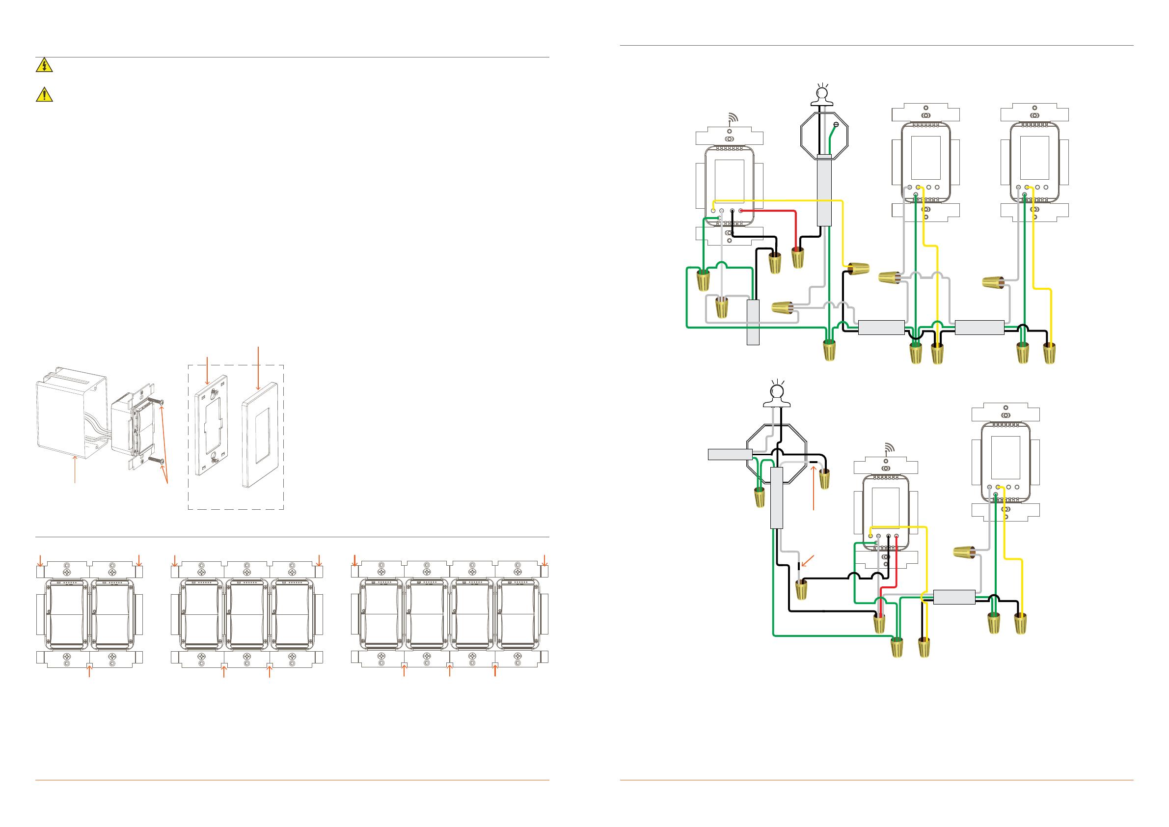
Multi-Gang Installations
When combining multiple keypads into a multi-ganged box, the outside tabs from one or both sides of each device so they all fit
into the electrical switch box. Below are examples of 2, 3 and 4-gang scenarios.
– Tabs are removed from both sides of the inside gang devices.
– Tabs are NOT removed from outside edges of the devices at the end of each gang.
Wiring Diagrams
The diagrams below display how to wire the Echo Auxiliary Control as a companion to the Echo Dimmer/Switch. Both the basic
wiring as well as the No Neutral diagrams are shown. Any unused wires must have the bare wire portion (stripped end) cut o and
the wire must be capped with a wire nut.
From
Power
Example of two Auxiliary Controllers wired to Echo Dimmer/Switch
From
Power
Black
Tape
Black
Tape
Example of one Auxiliary Control wired to Echo Dimmer (No Neutral)
WARNINGS:
– Using the Echo Dimmer or Keypad in a No Neutral configuration with loads other than incandescent is not supported.
– The Echo Switch is not supported in a No Neutral 3-way configuration.
Adapter
Electrical
Switch Box
Mounting
Screws
Wall Plate and Adapter
sold separately

