click GridPro User manual

Type
User manual

Click GridPro, a versatile electrical accessory mounting system, offers a range of possibilities for your home's electrical needs. With its compatibility with various Click front plates and the ability to be mounted on standard BS4662 flush-mounted boxes or surface-mounted using Click Mode or Polar Back boxes, it provides flexibility in installation. The system's dimmers can be easily assembled onto the mounting kit using the locking nut and nut runner tool, ensuring secure and proper alignment.

Click GridPro, a versatile electrical accessory mounting system, offers a range of possibilities for your home's electrical needs. With its compatibility with various Click front plates and the ability to be mounted on standard BS4662 flush-mounted boxes or surface-mounted using Click Mode or Polar Back boxes, it provides flexibility in installation. The system's dimmers can be easily assembled onto the mounting kit using the locking nut and nut runner tool, ensuring secure and proper alignment.

Important Note:
If dimmers are being used within a yoke
installation it is recommended they are
installed rst.
(See Dimmer Mounting Kit instructions).
Dimmer Kit Yoke Mounting Instructions
Isolate mains supply before commencing any work
Ensure back box is correctly positioned i.e. box must be ush to the wall.
Assemble all dimmers on to yoke using nut runner tool and locking nut. (Fig.4)
Do Not attach yokes to back box until all dimmers are attached and wired
according to instructions. (Fig.5)
Wire Dimmers according to instructions.
Ensure mounting yoke is earthed correctly using the earth terminal provided.
When all dimmers are assembled attach mounting yoke to suitable xed back box
according to the Yoke Attachment Instructions supplied with the yoke.
Ensure mounting yoke is earthed correctly using the earth terminal provided.
Arrange cables through the mounting yoke and connect the remaining modules
according to the General Installation Instructions (supplied with Yokes).
Check all connections thoroughly.
When the installation is complete attach front plate according to the Front Plate
Attachment Instructions supplied with the front plate.
Do not overtighten the xing screws.
Turn on mains supply to check operation of installation.
For cleaning / polishing of products, use only a soft, dry, clean cloth.
Note: When mounting dimmers on to multi-tier plates, only dimmers less than 60mm in height
must be used. Please speak to our technical team who will be able to assist.
GridPro Dimmer Mounting Kit
Safety Instructions
Safety Information
Please read the following information carefully before commencing installation.
Before commencing any electrical work, to prevent the
possibility of receiving an electric shock, ensure the mains
isolator on the consumer unit is in the ‘OFF’ position and
safely isolated in accordance with Best Practice Guide 3.
If in doubt consult a qualied electrician. The accessory plate must be installed in
accordance with the latest IET Wiring Regulations, BS7671.
If this product is being tted as a replacement part to an existing installation account
must be taken to the version of the wiring regulations it was installed to.
Dimmer Mounting on to 1 – 4 Gang Plates (Mode, Polar,
Deco, Deco+, Metalclad, Dene)
Please note all 1-4 gang GridPro front plates can be mounted in any British
Standard BS4662 ush mounted boxes. The product can also be surface mounted
using the standard Click Mode or Polar Back boxes.
Isolate mains supply.
Ensure the depth of the back box is the correct size for the installation (47mm
deep) and is securely xed to the wall.
When using a 1 Gang Plate it may be necessary to bend back or remove the top
and bottom lug of the back box if present. Alternatively you may nd it easier to
remove the clip feature on the module but this will make the module incompatible
with the GridPro yoke.
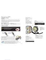
Assemble dimmer on to the mounting kit via the supplied locking nut and nut
runner tool.(Fig1.)
Please note that the dimmer spindle may be offset so the orientation of the dimmer
will need to be taken into account to achieve the desired assembled position.
(Fig.2)
Depending on the size of dimmer then a twin mounting kit may be required.(Fig.3)
Cable dimmer module according to instructions.
Check all connections thoroughly.
Mount accessory taking care to avoid trapping any cables. Do not overtighten the
xing screws.
Turn on mains supply to check operation of accessory
1. Nut Runner Tool
2. Dimmer Knob
3. Locking Nut
4. Front Plate
5. Mounting Module
6. Fixing Screw
7. Dimmer Module
Fig. 1
For larger dimmer modules a twin
mounting kit could be required
This allows the dimmer to be tted by
sacricing the module space next to it
Overhanging dimmer does not allow
room for adjacent module
Rotating dimmer on the offset spindle
moves the overhang to the other side
to allow adjacent module to be tted
Fig. 2
Fig. 3
Scolmore House | Mariner | Licheld Road Industrial Estate | Tamworth | Staffordshire | B79 7UL
United Kingdom
T: +44 (0)1827 63454 | F: +44 (0)1827 63362 | E: [email protected] | www.scolmore.com
Errors & Omissions excluded. Instructions are subject to change without notice. V. 3
For ease of installation it is
recommended that all dimmers
are installed rst prior to other
Grid Pro modules
All dimmers should be assembled on
to yoke before attaching the yoke to
the back box
Dimmer is assembled from the back
Fig. 5
Fig. 4
Note: When mounting dimmers on to multi-tier plates, only dimmers less than 60mm in height
must be used. Please speak to our technical team who will be able to assist.
  • Page 1 1
  • Page 2 2
  • Page 3 3
  • Page 4 4

click GridPro User manual

Type
User manual

Click GridPro, a versatile electrical accessory mounting system, offers a range of possibilities for your home's electrical needs. With its compatibility with various Click front plates and the ability to be mounted on standard BS4662 flush-mounted boxes or surface-mounted using Click Mode or Polar Back boxes, it provides flexibility in installation. The system's dimmers can be easily assembled onto the mounting kit using the locking nut and nut runner tool, ensuring secure and proper alignment.

Ask a question and I''ll find the answer in the document

Finding information in a document is now easier with AI