INSTALLATION INSTRUCTIONS
INSTRUCCIONES DE INSTALACIÓN
Verand
a
®
Gate Kit
Kit de puerta Verand
a
®
BOM-34107923
Read all instructions prior to installing product.
Refer to manufacturers safety instructions when operating any tools.
To register your product, please visit/ Para registrar su producto, visite:
To register your product, please visit/ Para registrar su producto, visite:
veranda.barretteoutdoorliving.com
• English ..............................................................................1
• Español .............................................................................5
Lea todas las instrucciones antes de instalar el producto
Consulte las instrucciones de seguridad del fabricante al utilizar herramientas

2
Tape Measure
Level
Hacksaw
Rubber Mallet
Drill
3
⁄
3
⁄
3
32
⁄32⁄
" and
1
⁄
1
⁄
1
8
⁄8⁄
" Drill Bits
#2 Square Drive Bit
3" Wood Blocks
Safety Glasses
Pencil
TOOLS NEEDED:
WARNING:
• Improper installation of this product can result in personal injury. Always wear safety goggles when
cutting, drilling and assembling the product.
• Incorrect installation may cause harm to the gate or individual.
• Not pool code approved.
NOTICE:
• DO NOT attempt to assemble the kit if parts are missing or damaged.
• DO NOT return the product to the store, for assistance or replacement parts call: 1-800-336-2383.
BEFORE YOU BEGIN:
Vinyl rail posts require an internal
support system for weight-bearing
purposes and therefore a post install
kit or wood post is required inside a
post jacket. Post install kit and wood
post needs to be purchased separately.
Top View of Post Jacket
Top View of Post Jacket
Rail
Rail
Purchased
Post Install Kit
Gate Kit
Component list:
QTY Description
2
Vinyl Uprights
2
Vinyl Rails
2
Aluminum Stiffeners
8
Balusters
4
Caps
1
Gravity Latch
2
Compact Butter y Hinges
6
1" Phillips Square Combo Screws
(For Gravity Latch)
8
1" Phillips Square Combo Screws (For Hinges)
8
#10 2
½
" Pan head Square Drive Screws
4
Glue
1
Allen Wrench (For Hinges)
Gravity Latch
1" Phillips Square
Drive Screws
Hinges
Allen Wrench
To obtain and review a copy of the warranty please go to: Veranda.BarretteOutdoorLiving.com/warranty.
You can also contact 1-877-279-4496 or write to Veranda, 7830 Freeway Circle, Middleburg Heights,
Ohio 44130 to obtain a copy of the warranty.
2
½
" Panhead
Square Drive Screws
Glue
Vinyl Balusters
Routed Vinyl Rails
Aluminum Stiffeners
Caps
Caps
Routed Vinyl Uprights

3
Measure Opening
Cut rails to needed length:
Measure opening between posts where gate will be
located. Subtract 2" from opening. This is the length
you will cut your rails for gate (Fig. 1).
NOTE:
Maximum width of opening between posts is 48".
Align top rail with bottom rail and cut both rails with
miter box or hacksaw (See saw blade manufacturer's
specs for correct blade) (Fig. 2).
Prior to cutting, be sure the spacing from the end of the
rail to the rst routed hole is the same on both ends,
which will allow for the gate balusters to be installed in
proportion.
NOTE:
Rails will insert 1 ¾" into gate pockets. Be sure
to allow a minimum of 2" from each end of the rail
for baluster clearance (Fig. 3). You may have
scenarios where you must cut over a baluster hole
and insert cut end into gate pocket.
Assemble rails for gate:
a. Lay bottom rail on a clean smooth surface and
snap balusters into routed holes (Fig. 4).
b. Repeat the process to connect the top rail
(Fig. 5).
Permanently attach rails to uprights:
a. Open glue and spread generously and evenly into
all four gate pockets. Glue must be spread along
all four sides of the gate pocket internally. When
inserting the rails into the pockets, this will spread
glue along the rail and bond the railing to the
pocket for maximum strength (Fig. 6).
NOTE:
You will need some glue at the end to
bond gate caps in place, so do not use all
of the glue.
b. Insert uprights on to assembled rail panel and
ensure the gate is square (Fig. 7). Once square,
allow glue to dry by waiting 15 minutes.
c. Once glue is dry, pre-drill down through the top
of each gate upright using a
1
⁄
1
⁄
1
8
⁄8⁄
" drill bit in the
locations shown in Figure 8. Using #10 2
1
⁄
1
⁄
1
2
⁄2⁄
" pan
head square drive screws provided, drive two
screws through the gate pockets locking the
gate pockets and railing together (Fig. 8). Repeat
this step at the top and bottom of each gate
upright for a total of four locations.
1
2
3
Fig. 1
Fig. 2
Fig. 4
Fig. 5
Fig. 6
Fig. 7
Fig. 8
(Not to Exceed 48")
Fig. 3
2" Minimum
Glue inside
pockets along all
4 sides

4
Attach caps to gate uprights:
a. Spread glue inside all four sides of the gate upright
and insert gate cap onto upright. The glue will
engage the tabs of the gate cap and bond the cap to
the upright (Fig. 9).
b. Repeat this step at the top and bottom of each gate
upright for a total of four locations.
c. Allow caps to dry.
Hang assembled gate onto post:
a. Cut two temporary wood blocks 3" tall (not
included), and rest bottom rail of gate on them.
Align gate between the posts (Fig. 11).
b. Secure hinges to posts with 1" Phillips screws as
provided with the hinges.
Mount hinges to gate:
a. Once gate is assembled, follow hinge instructions to
complete the installation.
NOTE:
For the top rail, the top of the hinges MUST be aligned
with the top of the top rail (Fig 10). This will ensure that the
top screw of the hinge is located to engage the top rail
pocket and internal aluminum stiffener. For the bottom rail,
the bottom of the hinge MUST be aligned with the bottom
of the bottom rail (Fig. 10). This will ensure that the bottom
screw of the hinge is located to engage the bottom rail
pocket and internal aluminum stiffener.
4
6
5
Fig. 9
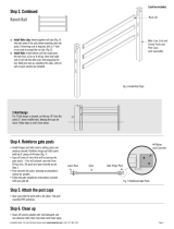
Install latch striker:
Latch striker must be centered along top rail (Fig. 12)
so that the screws engage the top rail, gate pocket, and
internal stiffener. Latch should be on the same side of
gate, opposite of hinges.
a. Once hinges are installed and gate is aligned and
level, mark pilot holes on the striker and pre-drill
using a
3
⁄
3
⁄
3
32
⁄32⁄
" bit. Using (2) of the 1" Phillips/square
drive pan head screws provided, secure the latch in
place.
b. Remove temporary wood blocks.
Install latch catch:
Align gravity latch catch with installed
latch striker (Fig. 12), mark pilot holes
on the latch, and pre-drill using a
3
⁄
3
⁄
3
32
⁄32⁄
"
bit. Using (4) of the 1" Phillips/square
drive pan head screws provided, secure
the latch in place.
7
8
Fig. 11
3" Spacer Blocks
Gate Post
Gate
Fig. 12
Latch Striker
Latch Striker
Latch Catch
Glue
Fig. 10
Top Hinge
Bottom Hinge

5
Cinta métrica
Nivel
Segueta
Martillo de goma
Taladro
Brocas de
3
⁄
3
⁄
3
32
⁄32⁄
" y
1
⁄
1
⁄
1
8
⁄8⁄
"
Punta de destornillador
cuadrado #2
Bloques de madera de 3"
(7,62 cm)
Gafas de protección
Lápiz
HERRAMIENTAS
QUE SE REQUIEREN:
ADVERTENCIA:
• La instalación incorrecta de este producto puede resultar en lesiones corporales. Utilice siempre gafas
de seguridad al cortar, taladrar y ensamblar el producto.
• La instalación incorrecta puede causar daños al portón o a personas.
• No aprobado por el código de piscinas.
AVISO:
• NO intente ensamblar el kit si faltan piezas o las piezas están dañadas.
• NO devuelva el producto a la tienda; para solicitar ayuda o piezas de repuesto, llame al: 1-800-336-2383.
ANTES DE COMENZAR:
Los postes del barandal de vinilo
requieren un sistema de soporte interno
para poder soportar el peso y, por
lo tanto, es necesario usar un kit de
instalación de postes o un poste de
madera dentro de la funda de poste.
El kit de instalación de postes y el poste
de madera se compran por separado.
Vista superior de la funda de poste
Vista superior de la funda de poste
Travesaño
Travesaño
Travesaño
Travesaño
Travesaño
Travesaño
Travesaño
Travesaño
Travesaño
Comprado Kit
de instalación
de poste
Lista de componentes
del kit de portón:
CANT. Descripción
2
Montantes de vinilo
2
Travesaño de vinilo
2
Refuerzos de aluminio
8
Barrotes
4
Tapones
1
Tranca de gravedad
2
Bisagras de mariposa compactas
6
Tornillos Phillips/Cuadrados de 1" (para el tranca
de gravedad)
8
Tornillos Phillips/Cuadrados de 1" (para las
bisagras)
8
Tornillos de cabeza alomada #10 de 2½"
4
Pegamento
1
Llave Allen (para las bisagras)
Tranca
de gravedad
Tornillos Phillips/
Cuadrados de 1"
Bisagras
Llave Allen
Para obtener y revisar una copia de la garantía, ir a: Veranda.BarretteOutdoorLiving.com/warranty.
También puede llamar al 1-877-279-4496 o escribir a Veranda, 7830 Freeway Circle, Middleburg Heights,
Ohio 44130 para obtener una copia de la garantía.
Tornillos de cabeza
alomada de 2½"
Pegamento
Barrotes de vinilo
Travesaño de
vinilo ranurados
Refuerzos de aluminio
Tapones
Tapones
Montantes
ranurados de vinilo

6
Medir la abertura
Cortar los travesaños a la longitud necesaria:
Medir la abertura entre los postes en donde se instalará
el portón. Restar 2" (5,08 cm) de la abertura. Esta es la
longitud a la que cortará los travesaños para el portón
(Fig. 1).
NOTA:
La anchura máxima de abertura entre los postes
es de 48" (121,92 cm).
Alinear el travesaño superior con el inferior y cortar
ambos travesaños con una segueta o caja de ingletes
(Consultar las especi caciones del fabricante de la hoja
de segueta para escoger la indicada) (Fig. 2).
Antes de cortar, comprobar que la distancia desde el
extremo del travesaño hasta el primero ori cio ranurado
sea la misma en ambos extremos, lo que le permitirá
instalar los barrotes del portón de forma proporcionada.
NOTA:
Los travesaños se insertarán 1
3
⁄
3
⁄
3
4
⁄4⁄
" (4,45 cm) en las
cavidades del portón. Asegurarse de dejar un mínimo
de 2" (5,08 cm) en cada extremo del travesaño para los
barrotes (Fig. 3). Puede haber situaciones donde será
necesario cortar un ori cio para barrote e insertar el
extremo cortado en la cavidad del portón.
Ensamblado de los travesaños del portón:
a. Colocar el travesaño inferior sobre una super cie
lisa y limpia y encajar los barrotes en los ori cios
ranurados (Fig. 3).
b. Repetir el proceso para conectar el travesaño
superior (Fig. 4).
Fijación permanente de los travesaños en los
montantes:
a. Abrir el pegamento y aplicar una cantidad
generosa y uniforme en las cuatro cavidades del
portón. El pegamento debe aplicarse en los cuatro
lados de la cavidad del portón, internamente. Al
insertar los travesaños en las cavidades, esta
acción se encargará de extender el pegamento
en el travesaño y adherir el travesaño a la cavidad
para una máxima resistencia (Fig. 6).
NOTA:
Necesitará algo de pegamento al nal para adherir
los tapones del portón en su lugar, de modo que
no utilice todo el pegamento.
b. Insertar los montantes en el panel del barandal
ensamblado y comprobar que el portón esté
cuadrado (Fig. 7). Una vez cuadrado, dejar secar
el pegamento durante 15 minutos.
c. Una vez que el pegamento esté seco, taladrar
hacia abajo a través de la parte superior de cada
montante de portón con una broca de 1⁄8" en
las ubicaciones que se muestran en la Figura 8.
Utilizando los tornillos de cabeza alomada #10 de
2 1⁄2" suministrados, atornillar dos tornillos en las
cavidades del portón, jando las cavidades con
el barandal (Fig. 8). Repetir este paso en la parte
superior e inferior de cada montante de portón en
un total de cuatro ubicaciones.
1
2
3
Fig. 1
Fig. 2
Fig. 4
Fig. 5
Fig. 6
Fig. 7
Fig. 8
No debe ser mayor
a 48" (121,92 cm)
Fig. 3
Un mínimo de 2" (5,08 cm)
Aplicar
pegamento en
el interior de las
el interior de las
cavidades en los
4 lados

7
Fig. 9
Fig. 11
Bloques espaciadores de 3" (7,62 cm)
Poste
de portón
Portón
Fig. 12
Traba de cerrojo
Traba de cerrojo
Tranca
Pegamento
Fijación de los tapones en los montantes del portón:
a. Extender el pegamento dentro de los cuatro lados
del montante de portón e insertar el tapón de portón
en el montante. El pegamento se esparcirá por las
lengüetas del tapón de portón y adherirá el tapón al
montante (Fig. 9).
b. Repetir este paso en la parte superior e inferior
de cada montante de portón en un total de cuatro
ubicaciones.
c. Dejar secar los tapones.
Colocación del portón ensamblado en el poste:
a. Cortar dos bloques de madera temporales a una de
altura de 3" (7,62 cm) (no incluidos), y descansar el
travesaño inferior del portón sobre ellos.
Alinear el portón entre los postes (Fig. 11).
b. Atornillar las bisagras en los postes con los tornillos
Phillips de 1" incluidos con las bisagras.
Instalación de la las bisagras en el portón:
a. Una vez que se ha ensamblado el portón, seguir las
instrucciones de las bisagras para nalizar la instalación
NOTA:
En el travesaño superior, la parte superior de las
bisagras TIENE QUE estar alineada con la parte superior
del travesaño superior (Fig. 10). De esta forma nos
aseguramos de que el tornillo superior de la bisagra esté
ubicado para encajar en la cavidad del travesaño superior
y el refuerzo de aluminio interior. En el travesaño inferior,
la parte inferior de la bisagra TIENE QUE estar alineada
con la parte inferior del travesaño inferior (Fig. 10). De
esta forma nos aseguramos de que el tornillo inferior de
la bisagra esté ubicado para encajar en la cavidad del
travesaño inferior y el refuerzo de aluminio interior.
4
6
5
Instalación de la traba de cerrojo:
La traba de cerrojo debe estar centrada en el travesaño
superior (Fig. 12), de modo que los tornillos atraviesen
el travesaño superior, la cavidad del portón y el refuerzo
interno. La traba debe estar en el mismo lado del
portón, en el lado opuesto de las bisagras.
a. Una vez que estén instaladas las bisagras y el portón
esté alineado y nivelado, marcar los agujeros guía en
la traba y taladrar con una broca de
3
⁄
3
⁄
3
32
⁄32⁄
".
Con los (2) tornillos Phillips/cuadrados
de 1" provistos, jar la traba en su lugar.
b. Remover los bloques de madera
temporales.
Instalación de la tranca de gravedad:
Alinear la tranca de gravedad con la traba
de cierre instalada (Fig. 12), marcar los
agujeros guía en la tranca y taladrar con
una broca de
3
⁄
3
⁄
3
32
⁄32⁄
". Con los (4) tornillos
Phillips/cuadrados de 1" provistos, jar la
tranca en su lugar.
7
8
Fig. 10
Bisagra superior
Bisagra inferior

BARRETTE OUTDOOR LIVING
7830 FREEWAY CIRCLE
MIDDLEBURG HEIGHTS, OHIO 44130
TEL: (800) 336-2383
WWW.VERANDA.BARRETTEOUTDOORLIVING.COM
/


