17/25
15
1x
1
1
2
3
1
2
1
2
1
2
888-24-304-G-00 rev. B • 10/14
ENGLISH
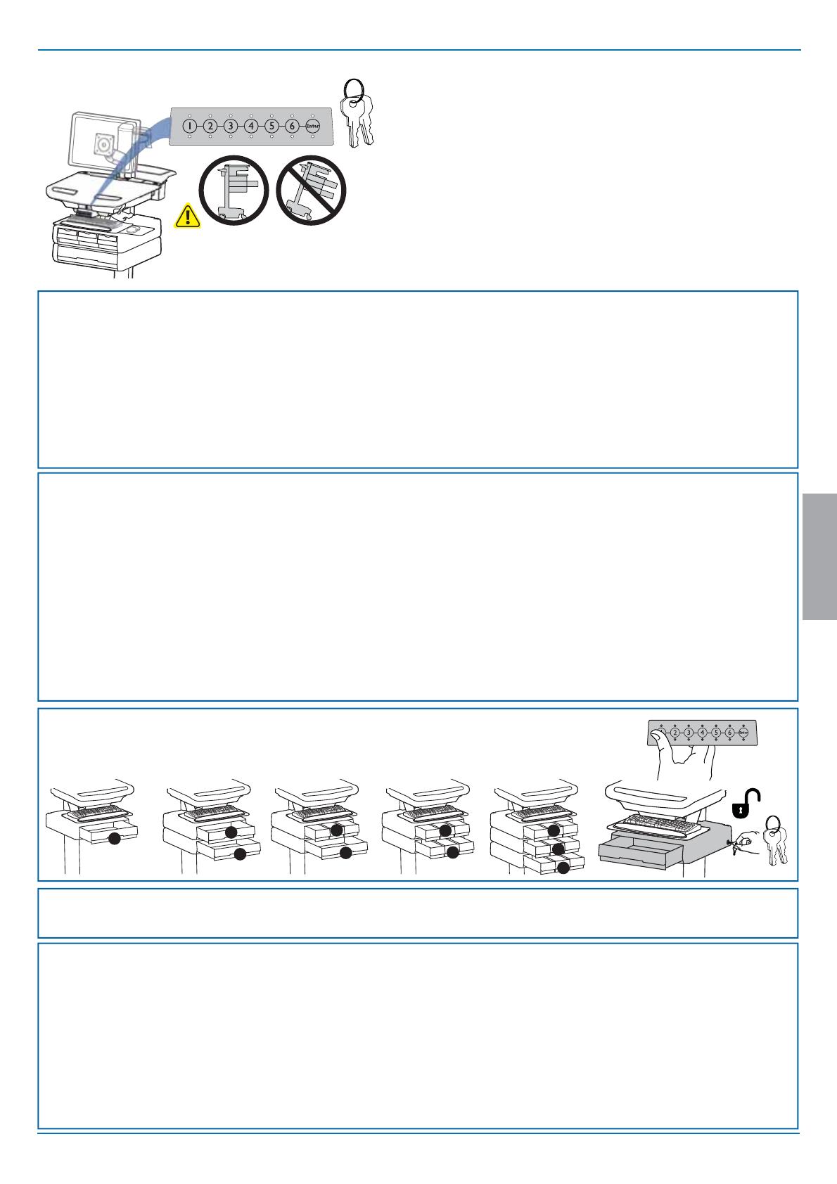
Auto-Lock Drawer
CAUTION: Open only one drawer at a time. Do Not
push cart when drawers are open. Failure to follow
these instructions may cause the cart to be unstable.
NOTE: User should change Master Personal Identi cation Number (PIN)
upon receipt of cart.
Lost Master PIN
Contact Ergotron Customer Care for instructions.
Ensure that the main power system batteries are installed and
functioning. The power does not need to be turned on at the power
system user interface.
*Drawer Row Numbers:
All PINs may vary in length from 4 – 7 digits. Number of PINs possible:
- Carts using StyleLink will store up to 1,000 PINs on the cart
- Carts not using StyleLink will store up to 100 PINs on the cart
- Ergotron recommends the following for choosing PIN digit length (assumes less than 1 in 25
chance of guessing random User PIN):
Max number of User PINs >50, 5+digit length recommended
Max number of User PINs >300, 6+digit length recommended
For maximum security use PIN length of 7
Set-up Master PIN for the First Time (Default Master PIN: 12345)
Contact Ergotron Customer Care for instructions if Master PIN is lost.
1. Enter default Master PIN (1-2-3-4-5) then press ENTER.
2. Press 5 for Master PIN Entry mode
3. Enter new Master PIN and press Enter (LEDs will blink green if PIN is accepted)
4. Master PIN entry mode will exit after 5 seconds of inactivity (LEDs blink red twice)
Master PIN Mode Menu
Enter Master PIN and then select one of the below numbers to enter that mode
1. User PIN Entry Mode
2. Pharmacy PIN Entry/Change Mode
5. Master Pin Change Mode
Programming Pharmacy PIN
1. Enter Master PIN and press ENTER for Mode Menu
2. Press 2 for Pharmacy PIN Entry Mode
3. Input Pharmacy PIN and press ENTER (all LEDs blink green in PIN is accepted).
4. Pharmacy PIN entry mode will exit after 5 seconds of inactivity (LEDs blink
red twice).
Programming User PINS
1. Enter Master PIN and press ENTER for Mode Menu.
2. Press 1 for User PIN Entry Mode.
3. Input new User PIN and press ENTER (All LEDs blink green if PIN is accepted). You may enter multiple USER PINs consecutively.
4. User PIN entry mode will exit after 5 seconds of inactivity (LEDs blink red twice).
NOTE: User PIN cannot be the same as a Master PIN or Pharmacy PIN. Once maximum User PIN storage is exceeded, the oldest User PIN will be over written.
Note: System will hold 1 Pharmacy PIN. Pharmacy PIN allows all drawers to unlock at the
same time. Drawers should then be opened at least slightly as the system will auto-lock after
10 seconds. All LEDs will ash green until system auto-locks. Once a drawer is opened the
corresponding LED for that row will light solid until it is placed back into its original location.
Lock Drawer:
• Wait 4 seconds for lock to engage automatically.
NOTE: Always ensure drawer is pushed in all the way and engaged with lock.
Drawer Troubleshooting
• No LEDs on keypad when pressing any number:
•Verify DC cable is connected from cart battery harness to controller.
• Verify keypad cable is connected to controller.
• Verify circuit breakers are not tripped and 5A fuse is installed in
battery harness.
• Drawer selection not available when User PIN is entered:
• Check to make sure drawer cable is installed securely.
• Remove power from drawer system for 10 seconds and re-apply.
• LEDs ash red/green after User PIN in entered:
• Battery charge is low, check to make sure USB charging cable is
plugged into computer and computer is ON.
LEDs/Alarm Meaning:
1,2,3,4, or 5 LED ON green: Corresponding Drawer is open.
1,2,3,4, or 5 LED ashing red and alarm sounding: Corresponding Drawer is open longer than 20
seconds. Mute alarm by pressing ashing button corresponding to open drawer.
All available drawer numbers ashing green: Waiting for drawer selection (see Unlock Drawer).
All LEDs ashing green: Pharmacy mode, all drawers are unlocked.
All LEDs blink red twice: PIN entry rejected/exit current mode after 5 seconds timeout.
All LEDs blink green 3 times: PIN entry accepted.
All LEDs ashing red: Firmware update in progress.
All LEDs ashing red/green: System power ON or low battery condition.
Unlock Drawer (2 methods): NOTE: All Drawers in row must be closed before a new row can be unlocked.
• Enter User PIN (only numbers for available drawer rows ash green), then press desired drawer row number*.
• Key - turn clockwise 1/4 turn


