Ergotron StyleView User guide

Category
Multimedia carts & stands
Type
User guide

Ergotron StyleView telemedicine cart is a versatile mobile workstation designed to enhance healthcare environments. It features an adjustable height LCD mount, a spacious worksurface, and a secure storage drawer for laptops or CPUs. The power system includes two batteries and an outlet box with medical-grade power outlets, allowing for uninterrupted operation. The cart also has a built-in keyboard tray with a tilt function and a USB hub for easy connectivity.

Ergotron StyleView telemedicine cart is a versatile mobile workstation designed to enhance healthcare environments. It features an adjustable height LCD mount, a spacious worksurface, and a secure storage drawer for laptops or CPUs. The power system includes two batteries and an outlet box with medical-grade power outlets, allowing for uninterrupted operation. The cart also has a built-in keyboard tray with a tilt function and a USB hub for easy connectivity.

1/29
StyleView® SV44 Telemedicine Cart
with Back-to-Back LCD and Power System
User's Guide - English
Guía del usuario - Español
Manuel de l’utilisateur - Français
Gebruikersgids - Deutsch
Benutzerhandbuch - Nederlands
Guida per l’utente - Italiano
Användarhandbok - svenska
ENGLISH
888-24-319-G-00 rev. C • 12/14
StyleView powered carts provide electrical AC power for mobile point of
care computing equipment in a healthcare environment. The carts are not
intended to power medical products or devices. Outlets are provided to
power information technology equipment only such as computer equipment,
computer peripherals, and teleconferencing system equipment.
Components / Tools Needed ................................................................................... 2
Features & Speci cations ................................................................................................. 3 - 4
Dimensions .............................................................................................................................5
Set-up .............................................................................................................................. 6 - 21
Battery Charge/Discharge .....................................................................................................7
Adjustment .................................................................................................................... 19-20
Auto-Lock Drawer .................................................................................................................21
Change Fuse (5 Amp) and Reset Circuit Breakers ..............................................................22
Change Power System Batteries ...................................................................................23 - 24
Cart Storage (long term/short term) ...................................................................................25
Ergonomics ...........................................................................................................................26
Maintenance & Safety ...................................................................................................26 - 29
For local customer care phone numbers visit: http://contact.ergotron.com
For the latest User Installation Guide and StyleLink Software Download please visit: www.ergotron.com
User Guide
2/29
AB C D
1
ABC D
1
2
3
4
5
6
7
14mm (9/16")
10mm
1x
#8-32
4x
1x
3/32"
1/2"
1/2"
4x
M4 x 10mm
4x
M4 x 10mm
1x
AB C D
1
2
3
AB C
1
1x
2x
1x
1x
M4 x 8mm
3x
2x
4x
1x
4x
1x
1x
1x
1x
1x
12x
1x
2x
M4 x 12mm
1x
M4 x 8mm
1x
1x
1x
1x
1x
8x
1x
4mm
M4 x 10mm
4x
M4 x 10mm
1x
3mm
1x
4x 8x
1x
2x
M4 x 14mm
1x
M4 x 6mm
4x
M4 x 25mm
2x
Camera Shelf
CPU Holder
Rear LCD Mount
ENGLISH
888-24-319-G-00 rev. C • 12/14
Components
Tools Needed
3/29
4/11
3
2
2a
1
9
8
7
14
21
22
20
17
17
13
10
6
5
12
23
18
19
16
15
ENGLISH
888-24-319-G-00 rev. C • 12/14
Features & Speci cations
This Class A digital apparatus complies with Canadian
ICES-003.
Cet appareil numérique de la classe A est conforme à la
norme NMB-003 du Canada.
FCC Compliance Statement
The cart has been tested and found to comply with the
limits for a Class A digital device, pursuant to part 15
of the FCC Rules. These limits are designed to provide
reasonable protection against harmful interference
when the equipment is operated in a commercial
environment. This equipment generates, uses, and can
radiate radio frequency energy and, if not installed and
used in accordance with the instruction manual, may
cause harmful interference to radio communications.
Operation of this equipment in a residential area is likely
to cause harmful interference in which case the user
will be required to correct the interference at his own
expense.
Changes or modi cations not expressly approved
by Ergotron, Inc. could void the user’s authority to
operate the equipment.
Please contact Ergotron for complete EMC compatibility
information.
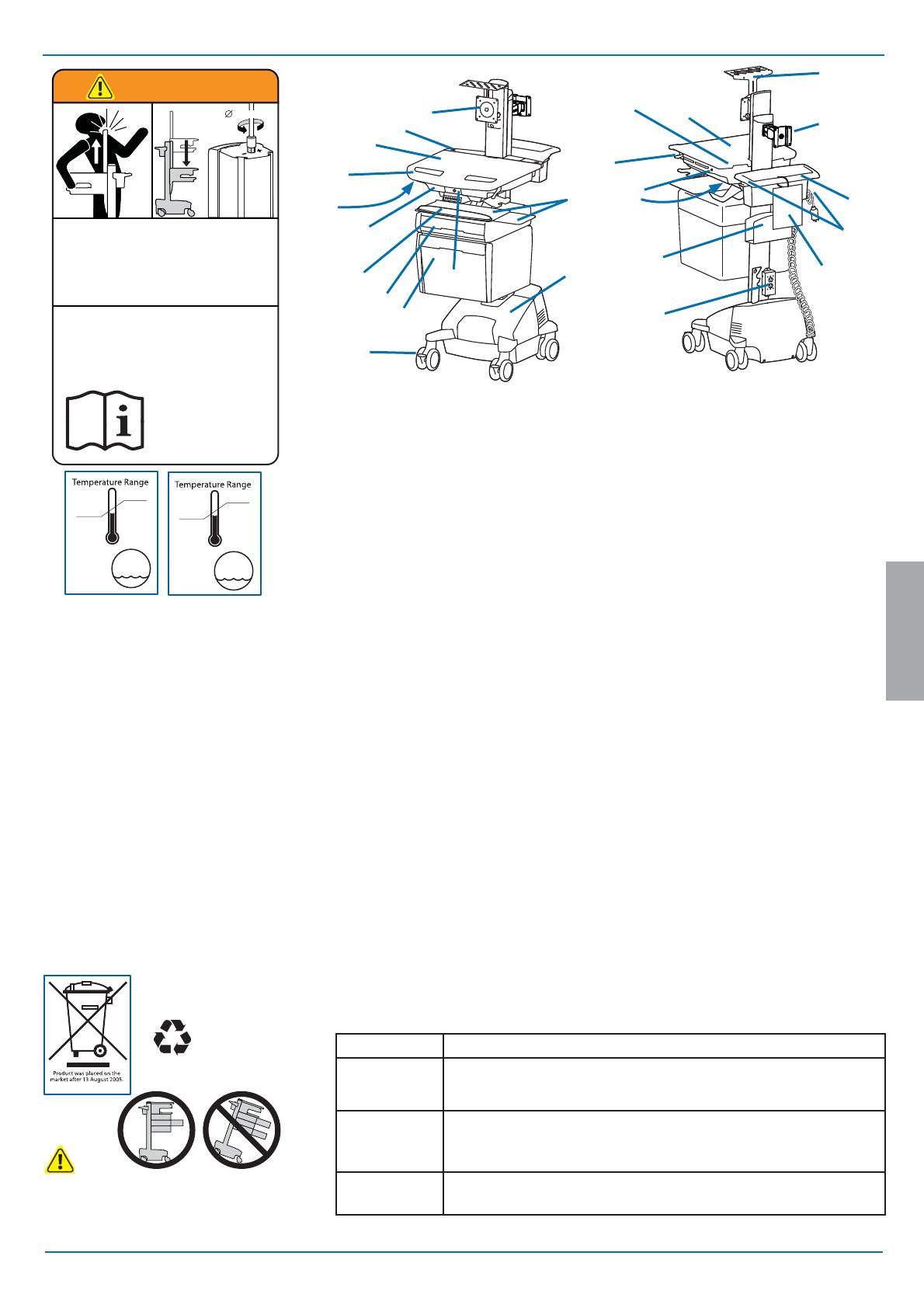
Worksurface 2a. Worksurface Lock and Release
User Interface for Power System
Secure Storage for Laptop, Thin Client or CPU
Front Handle
Height Adjustment Brake Handle
USB Hub inside connects keyboard and mouse USB cables. Ethernet port outside for easy network connection
Keyboard tray slides out, tilts and allows for right or left mousing with attached mouse holder
Keyboard Light under Front Handle
Keyboard Light Switch
Cable Management and Storage for excess cables and power supplies
Storage Basket and Rear Handle
Locking Casters
Quick Reference Card
Power Cord Hooks
LCD Mount attaches LCDs or tablet PC's with 75x75 or 100x100mm mounting interface
Antimicrobial worksurface and antimicrobial coating on wrist rest
Auto-Lock Drawer
Storage Drawer - includes dividers, 3 USB ports inside and 2 USB ports on back of drawer. 6' max USB cable
length for stored devices.
Camera Shelf -
camera is supplied by customer.
CPU Holder for codec- Holds components 1.38" -3.75" (35-95 mm) thick
Outlet Box, includes 2 power outlets:
North America: Medical Grade, 120VAC/60 Hz, 3 A max.
Europe/UK: 230VAC/50 Hz, 1.5 A max.
Saudi Arabia: 220VAC/60 Hz, 1.5 A max.
Power System
The StyleView AC Power System allows your power supply to travel with the cart. The Power System is
integrated in the base of the cart and comes standard with 2 batteries, power module, User Interface (UI), outlet
box and power cord.
• User Interface (UI): Allows power system output to be turned on or turned o , monitors battery charge
remaining, and provides low battery charge audible alarm.
Two 33 Ah Sealed Lead Acid, Absorbed Glass Mat, 12VDC batteries.
The minimum operational temperature is 10°C (50°F) and the maximum operational temperature is 29°C (86°F). The
recommended humidity range for operation is 5-95% rH.
The recommended cart storage temperature is 15°C (59°F). At this temperature, the batterys age-related
capacity loss is minimized. The minimum storage temperature is -20°C (-4°F) and the maximum storage
temperature is 50°C (122°F). The recommended humidity range for storage is 5-95% rH.
1.
2.
3.
4.
5.
6.
7.
8.
9.
10.
11.
12.
13.
14.
15.
16.
17.
18.
19.
20.
21.
22.
23.
Height Adjustable LCD Mount attaches LCDs or tablet PC's with 75x75 or
100x100mm mounting interface
BATTERY
LEAD
-20 °C
- 4 °F
50 °C
122 °F
Relative
Humidity
Range
5-95% rH
10 °C
50 °F
29 °C
86 °F
Relative
Humidity
Range
5-95% rH
Operational Storage
WARNING
IMPACT HAZARD!
MOVING PARTS CAN CRUSH AND CUT.
Failure to heed this warning may result in serious personal
injury or property damage!
www.ergotron.com
Minimize Lift Tension BEFORE:
Removing Mounted Equipment, Shipping Cart, Storing Cart.
826-501
14mm (9/16”)
AVERTISSEMENT
DANGER D’IMPACT!
LES PARTIES EN MOUVEMENT PEUVENT ÉCRASER ET COUPER.
Il existe un risque de blessure corporelle ou d’endommagement
matériel en cas de non respect de cet avertissement.
Minimisez la tension d’élévation AVANT:
de retirer l’équipement xé, d’expédier le chariot, de stocker le chariot
CAUTION: Close worksurface before opening drawers. Open only one
drawer at a time. Do Not push cart when drawers or worksurface are
open. Failure to follow these instructions may cause the cart to be
unstable.
Part Number Power System
SV44-57T1-1
Input: 120VAC/60 Hz, 5.1A;
Output: 120VAC/60 Hz, 400VA, 300W.
The cart and power system are certi ed to UL 60601 and CAN/CSA-C22.2 60601-1:08
SV44-57T1-2
SV44-57T1-3
SV44-57T1-B
Input: 230V~/50 Hz, 2.7A;
Output: 230V~/50 Hz, 400VA, 300W.
The cart and power system are compliant with EN 60601-1.
SV44-57T1-7
SV44-57T1-8
Input: 220V~/60 Hz, 2.7A;
Output: 220V~/60 Hz, 400VA, 300W.
4/29
20˚
24˚
12˚
<2 lbs (0.9 kg)
<2 lbs (0.9 kg)
<2 lbs (0.9 kg)
5"
(127 mm)
0 lbs (0 kg)
<5 lbs (2.3 kg)
<13 lbs (5.9 kg)
90˚90˚
< 2 lbs (1 kg)
A+B< 25 lbs
(11.3 kg)
A
B
11.8"
(300 mm)
< 23 lbs
(10.5 kgs)
<5 lbs (2.3 kg)
ENGLISH
888-24-319-G-00 rev. C • 12/14
With Independent LCD Lift:
6-14 lbs (2.7-6.4 kg)
Without Independent LCD Lift:
20 lbs (9 kg)*
* See "How To Eliminate Independent LCD
Lift" section
Weight Capacity
*Combined LCD and CPU Compartment weight:
<27 lbs (12.2 kg).
Features & Speci cations
Open Worksurface
Closed Worksurface
CPU Compartment
CAUTION:
If the combined LCD and CPU weight is greater than 27 lbs (12.2 kg) then the CPU must be
mounted to the rear of the cart and codec (if present) can be placed into the CPU compartment.
IMPORTANT! This product will need tension adjustments once installation is complete. Make sure all equipment is properly installed on the product before attempting
range of motion or tension adjustments. Any time equipment is added or changed on this product resulting in a di erent mounted weight, you should repeat the
adjustment steps to ensure safe and optimum operation. This product should move smoothly and easily through the full range of motion and stay where you set it. If
movement is di cult or the product does not stay where you set it, follow the adjustment instructions to loosen or tighten the tension to create a smooth, easy motion.
Depending on your product and the adjustment, it may take many turns to notice a di erence.
5/29
7" - 12"
(178-305 mm)
17"
(432 mm)
50.5"
(1283 mm)
2.9" (74 mm)
43"
(1092 mm)
3.4"
(86 mm)
1.75" (44 mm)
13"
(330 mm)
4"
(102 mm)
23" - 43"
(584-1092 mm)
31" - 51"
(787-1295 mm)
14.63"
(372 mm)
13.4"
(340 mm)
15.5"
(394 mm)
18.3"
(465 mm)
31"
(787 mm)
2.5"
(64mm)
19.75"
(502 mm)
22.38"
(568 mm)
< 14.75" (375 mm)**
< 2.75" (70 mm)
< 4" (102 mm)
*
< 12.25"
(311 mm)
< 12.25"
(311 mm)
*< 21.75"
(552 mm)
*< 17.63"
(448 mm)
*< 17.75"
(451 mm)
< 13"
(330 mm)
**< 2.75"
(70 mm)
< 2.3"
(58 mm)
**< 4.25"
(108 mm)
**< 7.75"
(197 mm)
**< 8"
(203 mm)
**< 2.75"
(70 mm)
**< 4"
(102 mm)
< 1.38"
(35 mm)
Side View
Top View
Front View
17.5"
(445 mm)
15.4"
(390 mm)
7.4"
(188 mm)
3.7"
(95 mm)
3.27"
(83 mm)
12.5"
(315 mm)
10.5"
(267 mm)
2.5"
(64 mm)
Front View
12.6"- 24.4”
(320-620 mm)
11"
(280 mm)
15.6"
(395 mm)
Side View
8.5"
(216 mm)
Top View
15"
(383 mm)
11.2"
(285 mm)
4.5"
(114 mm)
2"
(51 mm)
5.7"
(145 mm)
13"
(332 mm)
15.5"
(393 mm)
ENGLISH
888-24-319-G-00 rev. C • 12/14
Dimensions
When  guring dimensions, include
mounted accessories, protruding cables
and port replicators or docking stations.
CPU Compartment
*Auto-Lock Drawer
6/29
1
b
c
3
a
2
abc
d
ENGLISH
888-24-319-G-00 rev. C • 12/14
Set-up
Release Brake to move riser.
CAUTION! Completely release brake
engagement before raising or lowering
the cart. Raising or lowering the cart with
the brake partially engaged may cause
product damage.
7/29
4
ab c
8hrs
7 hrs
07.00
ENGLISH
888-24-319-G-00 rev. C • 12/14
Set-up
Battery Charge/Discharge
Initial Power on/Charge Battery (takes approximately 7 hours to charge)
Turn on power system by holding power button down for
1 - 3 seconds.
With cart's power cord
plugged into the wall
outlet, wait until cart is
at 100% charge. (takes
aproximately up to 7 hours
to charge)
Plug Cart's Power Cord into wall outlet.
Do Not stretch coiled cord further than 8 feet
(2.5 meters), damage to the cord may occur.
Battery has 100% charge.
Light  ashes when charging (power cord plugged into wall outlet)
Allow battery to continue
charging until light stops  ashing. After light stops  ashing, it is OK to unplug the
power cord from the wall.
You can use cart while charging.
Battery has less than 90% charge.
Battery has less than 70% charge.
Battery has less than 50% charge.
Battery has less than 30% charge. Light is red and alarm beeps. Plug-in power cord and charge
to 100%! You can use cart while charging.
Alarm Mute button. Pressing this will temporarily mute alarm.
Power button for internal power system outlets. Pressing this will provide or remove power to/
from components plugged into the internal outlets.
When lit, alarm is enabled and
will beep when battery charge
gets below 30%. For details on
enabling and disabling alarm
contact Ergotron Customer Care.
When lit, the power system is on.
When dark, power system is o .
This power system interface will alert you to the percentage of charge remaining in the cart battery with a series of steady or ashing red,
yellow or green lights, and an alarm that will beep when charge gets below 30%. Remember, the battery needs to be charged to 100%
every day, and you can use the cart while charging, so plug-in cord as often as possible to avoid running out of power!
NOTE: Put monitor in power save mode to optimize battery run time.
NOTE: Frequent operation of the cart while battery charge levels are
below 30% will signi cantly reduce the life of your battery and may
void your battery warranty.
CAUTION: There is no on/o switch on
this equipment; the AC power cord is the only
power disconnect. The socket outlet should be
easily accessible and should be installed near the
equipment.
8/29
5
a
b
c
1x
1x
1x
1x
1x
ENGLISH
888-24-319-G-00 rev. C • 12/14
Set-up
9/29
6
ab
c
7
a
cbd
4mm
ENGLISH
888-24-319-G-00 rev. C • 12/14
Set-up
Connect Keyboard and Mouse to USB Hub
NOTE: Bar Code Scanner should be connected directly to
computer USB port.
DO NOT connect Bar Code Scanner to the USB Hub.
USB (Type A)
USB (Type A)
10/29
9
1x
M4 x 6mm
ab
10
b
8
a
M4 x 5mm
1x
75x75mm / 100x100mm
M4 x 10mm
4x
1x
M4 x 14mm
ENGLISH
888-24-319-G-00 rev. C • 12/14
Set-up
If your monitor has recessed
mounting holes,
you need to add the provided
spacer between
the monitor and the mounting
plate.
Raise monitor to top of vertical adjustment BEFORE removing.
DO NOT remove Stop Screw without monitor attached. Doing so will
cause monitor pivot to shoot up rapidly and may cause personal injury.
826-502
1.
2.
3.
Élevez l’écran au plus haut de l’ajustement vertical AVANT de le retirer.
NE retirez PAS la vis d’arrêt avant que l’écran soit xé.
Dans un tel cas, le pivot d'écran se relèverait rapidement et cela pourrait
engendrer des blessures.
WARNING
AVERTISSEMENT
IMPACT HAZARD!
MOVING PARTS CAN CRUSH AND CUT.
Failure to heed this warning may result in serious personal
injury or property damage!
www.ergotron.com
DANGER D’IMPACT!
LES PARTIES EN MOUVEMENT PEUVENT ÉCRASER ET COUPER.
Il existe un risque de blessure corporelle ou d’endommagement
matériel en cas de non respect de cet avertissement.
11/29
cd
10
11
a
b
a
b
c
d
1x
M4 x 14mm
ENGLISH
888-24-319-G-00 rev. C • 12/14
Set-up
3 Mounting Options
12/29
12
11
2x
1x
2x
M4 x 12mm
ab
dc
ENGLISH
888-24-319-G-00 rev. C • 12/14
Set-up
Plug in power cables.
WARNING! Connecting electrical equipment to the outlet
e ectively leads to creating a medical system and the
result can be a reduced level of safety.
To increase space and improve air ow, power brick may be stored under the storage area.
13/29
13
4x
2x
aa
bb
4x
4x
1x 1x
4x
M4 x 10mm
ENGLISH
888-24-319-G-00 rev. C • 12/14
Set-up
Place computer and AC power adaptors in compartment. Do not place power bricks near
computer or compartment air vents.
14/29
1
e
f
d
2
1x
c
ENGLISH
888-24-319-G-00 rev. C • 12/14
Set-up
DO NOT OBSTRUCT AIR VENTS!
Obstructing air vents may cause overheating and result in
equipment damage.
If computer with cables is too wide, then
follow these instructions.
Placement of CPU's in Secure Storage Area:
Center CPU in storage area.
Thin ClientUSFF (Ultra Small Form Factor)
To increase space and improve air ow,
power brick may be stored under the storage
area.
WARNING: Fan must always
be running when computer
is on. Operating computer
without fan may lead to
overheating, resulting
in reduced equipment
performance.
Plug the following factory connected cables into your computer.
USB: This cable runs from the USB Hub to your computer and uses your computer to power the USB Hub, Keyboard
Lights and Fan. (NOTE: Your computer must be turned on for the USB Hub, Keyboard Lights and Fan to function).
Optional StyleLink: This USB cable runs from the power system to your computer for StyleLink Software. For more
info on StyleLink visit: http://4support.ergotron.com.
Ethernet: This cable runs from the side of the enclosure to your computer to allow network connection from the
ethernet port on the outside of the enclosure.
15/29
14
2x
a
fg
de
bc
1x
1x
4x
8x
ENGLISH
888-24-319-G-00 rev. C • 12/14
Set-up
16/29
15
M
4 x 10 mm
M4 x 10 mm
#8-32
4x
3/32"
!
75 mm
100 mm
4x
M
4 x 10 mm
M4 x 10 mm
4x
16
ENGLISH
888-24-319-G-00 rev. C • 12/14
Set-up
If your monitor uses a screw size other than M4 x 10mm, DO NOT
use the M4 x 10mm screws or knob provided as they could result in
damage to the monitor.
17/29
18
17
1/2"
1/2"
1/2"
1/2"
ENGLISH
888-24-319-G-00 rev. C • 12/14
Set-up
Increase Friction
If this product moves too easily from
side-to-side, then you'll need to
increase friction:
Decrease Friction
If this product is too di cult to move
from side-to-side, then you'll need to
decrease friction:
Increase Friction
If this product moves too easily from
side-to-side, then you'll need to
increase friction:
Decrease Friction
If this product is too di cult to move
from side-to-side, then you'll need to
decrease friction:
Side-to-Side Motion
Move monitor side-to-side through entire range of motion. If it does not stay in place at any
point it will need adjustment - see below. Adjust so side-to-side moving forces are equal.
Adjust Side-to-Side
Tilt Motion
Tilt monitor up and down through entire pivot range of motion. If it does not stay in place or move-
ment in one direction is sti , pivot needs adjustment - see below. Adjust until monitor stays in place
and tilting forces, up or down, are equal.
Adjust Tilt
18/29
20
21
1x
1x
19
21
1/2"
ENGLISH
888-24-319-G-00 rev. C • 12/14
Set-up
Keyboard Light
1. Turn Computer on.
2. Test Keyboard Light.
Keyboard Light will automatically turn o
after 15 minutes if not manually turned o .
Portrait/Landscape
Rotate monitor from Portrait to Landscape through entire range of motion. If it does not stay in place
or movement in one direction is sti , tension needs adjustment - see below. Adjust until monitor stays
in place and tension, portrait to landscape, is equal.
Adjust Portrait/Landscape
To Increase Tension: Turn screw clockwise.
To Decrease Tension: Turn screw counterclockwise.
19/29
22
14mm (9/16")
b
a
M4 x 8mm
1x
ENGLISH
888-24-319-G-00 rev. C • 12/14
Adjustment
Release Brake to move riser.
Follow these instructions to tighten or loosen tension.
It is important that you adjust this product according to the weight of the mounted equipment as described in the following steps. Any time equipment is added or removed from this
product, resulting in a change in the weight of the mounted load, you should repeat these adjustment steps to ensure safe and optimum operation.
Adjustments should move smoothly and easily through the full range of motion and stay where you set it. If adjustments are di cult and do not stay in the desired position, follow
the instructions to loosen or tighten the tension to create a smooth, easy adjustment motion. Depending on your product and the adjustment, it may take several turns to notice a
di erence.
Lift – Up and down
NOTE: Adjustment
may require 40 - 60
revolutions.
Loosen knob, tilt Display to desired
position then retighten knob.
Tilt – Forward and Backward
20/29
c
1x
M4 x 8mm
10mm
d
ENGLISH
888-24-319-G-00 rev. C • 12/14
Adjustment
Follow these instructions to tighten or loosen tension.
Lift – Up and down
To Stop Independent LCD Lift
For heavier Displays or when using a
Tablet PC, you can keep the LCD Lift from
moving out of position, by installing this
screw into one of the three holes on the
back of the riser depending on the desired
height.
With Independent
LCD Lift:
6-14 lbs (2.7-6.4 kg)
Without Independent
LCD Lift
:
20 lbs (9 kg)
Follow these instructions to tighten or loosen tension.
Pan - Side-to-Side
Raise monitor to top of vertical adjustment BEFORE removing.
DO NOT remove Stop Screw without monitor attached. Doing so will
cause monitor pivot to shoot up rapidly and may cause personal injury.
826-502
1.
2.
3.
Élevez l’écran au plus haut de l’ajustement vertical AVANT de le retirer.
NE retirez PAS la vis d’arrêt avant que l’écran soit xé.
Dans un tel cas, le pivot d'écran se relèverait rapidement et cela pourrait
engendrer des blessures.
WARNING
AVERTISSEMENT
IMPACT HAZARD!
MOVING PARTS CAN CRUSH AND CUT.
Failure to heed this warning may result in serious personal
injury or property damage!
www.ergotron.com
DANGER D’IMPACT!
LES PARTIES EN MOUVEMENT PEUVENT ÉCRASER ET COUPER.
Il existe un risque de blessure corporelle ou d’endommagement
matériel en cas de non respect de cet avertissement.
  • Page 1 1
  • Page 2 2
  • Page 3 3
  • Page 4 4
  • Page 5 5
  • Page 6 6
  • Page 7 7
  • Page 8 8
  • Page 9 9
  • Page 10 10
  • Page 11 11
  • Page 12 12
  • Page 13 13
  • Page 14 14
  • Page 15 15
  • Page 16 16
  • Page 17 17
  • Page 18 18
  • Page 19 19
  • Page 20 20
  • Page 21 21
  • Page 22 22
  • Page 23 23
  • Page 24 24
  • Page 25 25
  • Page 26 26
  • Page 27 27
  • Page 28 28
  • Page 29 29

Ergotron StyleView User guide

Category
Multimedia carts & stands
Type
User guide

Ergotron StyleView telemedicine cart is a versatile mobile workstation designed to enhance healthcare environments. It features an adjustable height LCD mount, a spacious worksurface, and a secure storage drawer for laptops or CPUs. The power system includes two batteries and an outlet box with medical-grade power outlets, allowing for uninterrupted operation. The cart also has a built-in keyboard tray with a tilt function and a USB hub for easy connectivity.

Ask a question and I''ll find the answer in the document

Finding information in a document is now easier with AI