
Wireless Innovations Group
2601 Telecom Parkway
Richardson, Texas 75082
400/800 MHz Fiber Optic & RF Fed Bi-Directional
Amplifier Operations / Maintenance Manual
DWG NO:
Error! Not a valid link.
Rev:
Error!
Not a
valid
link.
Date
:06/16/2004
Page:
1
of 63
OPERATIONS / MAINTENANCE MANUAL
For
400MHz Fiber Optic Fed & RF Fed
Bi-Directional Amplifier
AE04A-D1248-001
AE04A-D1246-001
800MHz Fiber Optic Fed & RF Fed
Bi-Directional Amplifier
AE04A-D1437-001
AE04A-D1436-001
MANUAL NO. AE04B-A1669
REVISION A
The information set forth in this document and all rights in and to
inventions disclosed herein, and patents that might be granted
thereon disclosing, employing or covering the materials, methods,
techniques or apparatus described herein are the exclusive
property of Andrew Corporation.
This document is an operation and maintenance manual. No
disclosure or reproduction of the information or drawings shall be
made of any other purpose without the prior written consent of
Andrew Corporation. Use of the information contained herein to
fabricate or assemble any item in whole or in part is expressly
prohibited.

Wireless Innovations Group
2601 Telecom Parkway
Richardson, Texas 75082
400/800 MHz Fiber Optic & RF Fed Bi-Directional
Amplifier Operations / Maintenance Manual
DWG NO:
Error! Not a valid link.
Rev:
Error!
Not a
valid
link.
Date
:06/16/2004
Page:
2
of 63
Table of Contents
INTRODUCTION ..................................................................................................................................... 5
Scope.........................................................................................................................................................................5
Purpose.....................................................................................................................................................................5
G
LOSSARY OF
T
ERMS
................................................................................................................................6
1.0
SAFETY CONSIDERATIONS ..................................................................................................... 7
1.1
Electric Shock Hazard ...............................................................................................................................7
1.2 Hot Surface Hazard ...................................................................................................................................7
1.3
Optical Laser Hazard ................................................................................................................................7
1.4 Emergency Contact Numbers ...................................................................................................................7
2.0
EQUIPMENT OVERVIEW / DESCRIPTION ........................................................................... 8
3.0
SPECIFICATION .......................................................................................................................... 8
3.1 Parts Lists ...................................................................................................................................................9
3.1.1 400 MHz Bi-Directional Amplifier ....................................................................................................9
3.1.2 800 MHz Bi-Directional Amplifier
....................................................................................................9
3.2
Electrical Specifications.............................................................................................................................9
3.2.1 400 MHz Bi-Directional Amplifier Downlink Specification............................................................9
3.2.2 400 MHz Bi-Directional Amplifier Uplink Specification
...............................................................10
3.2.3 800 MHz Bi-Directional Amplifier Downlink Specification..........................................................10
3.2.4 800 MHz Bi-directional Amplifier Uplink Specification ...............................................................11
3.3 Mechanical Specifications........................................................................................................................11
3.4
Environmental Specifications..................................................................................................................12
4.0 EQUIPMENT P
H
OTOGRAPHS ................................................................................................ 12
4.1 400 MHz Fiber Optic Fed Bi-Directional Amplifier ..................................................................................12
4.2 800 MHz Fiber Optic Fed Bi-Directional Amplifier ..................................................................................13
5.0
MODULES .................................................................................................................................... 14
5.1
400 MHz EO Cell Amplifier Module (AE04A-D1264-001) ..................................................................14
5.1.1 Description ....................................................................................................................................14
5.1.2 Specification..................................................................................................................................15
5.1.3
Photographs
..................................................................................................................................15
5.1.4
Schematics..................................................................................... Error! Bookmark not defined.
5.2 480 MHz High Isolation Duplexer (AE04A-D1442-001) ......................................................................26
5.2.1
Description
....................................................................................................................................26
5.2.2 Specification..................................................................................................................................26
5.2.3 Photograph....................................................................................................................................27
5.3
480 MHz Low Isolation Duplexer (AE04A-D1443-001) .......................................................................27
5.3.1 Description ....................................................................................................................................27
5.3.2 Specification..................................................................................................................................28
5.3.3 Photograph ...................................................................................................................................28
5.4
800 MHz EO Cell Amplifier Module (AE04A-D1265-001) ..................................................................28
5.4.1 Description ....................................................................................................................................28
5.4.2 Specification..................................................................................................................................29
5.4.3 Photographs..................................................................................................................................30
5.4.4 Schematics.....................................................................................................................................32
5.5 800 MHz High Isolation Duplexer (AE04A-D1438-001) ......................................................................38
5.5.1
Description ....................................................................................................................................38
5.5.2 Specification..................................................................................................................................38

Wireless Innovations Group
2601 Telecom Parkway
Richardson, Texas 75082
400/800 MHz Fiber Optic & RF Fed Bi-Directional
Amplifier Operations / Maintenance Manual
DWG NO:
Error! Not a valid link.
Rev:
Error!
Not a
valid
link.
Date
:06/16/2004
Page:
3
of 63
5.5.3
Photograph
....................................................................................................................................39
5.6
Fiber Optic Transceiver Module (AE04A-D1100-009).........................................................................39
5.6.1 Description ....................................................................................................................................39
5.6.2
Specification
..................................................................................................................................40
5.6.3
Photographs..................................................................................................................................41
5.6.4 Schematics.....................................................................................................................................42
5.7 +48V Power Supply Module (AE04A-D0803-002) ................................................................................51
5.7.1
Description ....................................................................................................................................52
5.7.2 Specification..................................................................................................................................52
5.7.3 Photographs..................................................................................................................................53
5.7.4
Schematics.....................................................................................................................................54
5.8 Alarm Module (AE04A-D0805-007): Optional......................................................................................55
5.8.1 Description ....................................................................................................................................55
5.8.2
Photographs
..................................................................................................................................55
5.8.3 Schematics.....................................................................................................................................57
6.
INSTALLATION.......................................................................................................................... 61
6.1
BDA Installation & Gain Setup ..............................................................................................................61
7.
BDA MAINTENANCE /
TROUBLESHOOTING
& M
ODULE CARE
............................................. 64
7.1 Maintenance .............................................................................................................................................64
7.2
BDA Troubleshooting Procedure ...........................................................................................................64
7.3 Tools & Test Equipment..........................................................................................................................64
7.4 Module Care .............................................................................................................................................65
7.4.1 Module Removal....................................................................................................................................65
7.4.2 Module Installation ...............................................................................................................................65
7.4.3
Alarm Module Removal (Optional Equipment) ...................................................................................66
7.4.4 Alarm Module Installation (Optional Equipment)..............................................................................66
7.4.5 Module Transportation .........................................................................................................................66
7.4.6 BDA Connections..................................................................................................................................66

Wireless Innovations Group
2601 Telecom Parkway
Richardson, Texas 75082
400/800 MHz Fiber Optic & RF Fed Bi-Directional
Amplifier Operations / Maintenance Manual
DWG NO:
Error! Not a valid link.
Rev:
Error!
Not a
valid
link.
Date
:06/16/2004
Page:
4
of 63
AMENDMENT RECORD SHEET
Rev
Nō.
Date ECN Reason Page
Amended
Incorpor
ated By
A
6/16/04 1
st
Issue J. Hsu/
E. Yearby

Wireless Innovations Group
2601 Telecom Parkway
Richardson, Texas 75082
400/800 MHz Fiber Optic & RF Fed Bi-Directional
Amplifier Operations / Maintenance Manual
DWG NO:
Error! Not a valid link.
Rev:
Error!
Not a
valid
link.
Date
:06/16/2004
Page:
5
of 63
INTRODUCTION
Scope
This handbook is for use solely with the equipment identified by the Andrew Part Numbers
shown on the front cover. It is not to be used with any other equipment unless specifically
authorized by Andrew Corporation.
Purpose
The purpose of this handbook is to provide the operator/maintainer with sufficient
information to operate, maintain and repair the equipment while in the filed. All repairs and
adjustments that are not filed repairable will be performed by Andrew Corporation
Richardson, Texas facility.
Limitation of Information Notice
This manual is written for the use of technically competent operators/service persons. No
liability is accepted by Andrew Corporation for the misuse of the information contained
within this manual.

Wireless Innovations Group
2601 Telecom Parkway
Richardson, Texas 75082
400/800 MHz Fiber Optic & RF Fed Bi-Directional
Amplifier Operations / Maintenance Manual
DWG NO:
Error! Not a valid link.
Rev:
Error!
Not a
valid
link.
Date
:06/16/2004
Page:
6
of 63
GLOSSARY OF TERMS
ALC
Automatic Level Control
AC
Alternating Current
BDA
Bi-Directional Amplifier
C/N
Carrier-to-Noise Ratio
DC
Direct Current
dB
Decibel
dBc
Decibel Below Carrier
dBm
Decibel referenced to 1 mW
ESD
Electrostatic Discharge
EMI
Electromagnetic Interference
FC/APC
Fiber Connector /Angle Polish Connector
GND
Ground
HPA
High Power Amplifier
Hz
Hertz
kHz
Kilohertz
kM
Kilometer
LED
Light Emitting Diode
LPA
Low Power Amplifier
MHz
Megahertz
mW
Milliwatt
nm
nanometer
NF
Noise Figure
OIP3
Output Third-Order Intercept Point
Ω
Ohm
RF
Radio Frequency
Rx
Receiver
Tx
Transmitter
V
Volt
VAC
Volt Alternating Current
VSWR
Voltage Standing Wave Ratio

Wireless Innovations Group
2601 Telecom Parkway
Richardson, Texas 75082
400/800 MHz Fiber Optic & RF Fed Bi-Directional
Amplifier Operations / Maintenance Manual
DWG NO:
Error! Not a valid link.
Rev:
Error!
Not a
valid
link.
Date
:06/16/2004
Page:
7
of 63
1.0 SAFETY CONSIDERATIONS
1.1 Electric Shock Hazard
To avoid electric shock, switch the BDA “OFF” prior to performing any repairs. All repairs beyond
modular replacement must be performed by Andrew Trained Technicians.
1.2 Hot Surface Hazard
RF power into the BDA will be limited by the use of high power attenuators. These attenuators
will be located at the transmitter source. Caution should be taken when working near high
power attenuators due to the risk of being burned by its hot surface.
Due to the amount of heat dissipated by the BDA heat fins, caution should be taken when
working near heat fins due to the risk of being burned by its hot surface.
1.3 Optical Laser Hazard
To avoid injury to the eyes, do not look directly into fiber optic transceiver transmit port (Tx).
1.4 RF Exposure warning
The installer must mount the downlink transmit antenna in a manner that will insure a
minimum separation distance of 40 cm. from the user or nearby persons.
1.5 Emergency Contact Numbers
Andrew Engineering Department contact information:
Andrew Corporation
Attn: Wireless Innovations Group
2601 Telecom Parkway
Richardson, Texas U.S.A. 75082-3521
Telephone: 972-952-9700
Fax: 972-952-0018

Wireless Innovations Group
2601 Telecom Parkway
Richardson, Texas 75082
400/800 MHz Fiber Optic & RF Fed Bi-Directional
Amplifier Operations / Maintenance Manual
DWG NO:
Error! Not a valid link.
Rev:
Error!
Not a
valid
link.
Date
:06/16/2004
Page:
8
of 63
2.0 EQUIPMENT OVERVIEW / DESCRIPTION
MBTA System Wide Radio Tunnel Antenna Distribution System provides extended radio
coverage within MBTA rail transit tunnels. The new tunnel antenna system is a two-way
communication system consisting of 400 MHz base transceiver stations, 800 MHz base
transceiver stations, antennas, radiating cable, fiber optic cable and BDAs. Both the 400
MHz and 800 MHz systems operate independently. The 400 MHz system operate as a
conventional analog voice communication system and the 800 MHz system operate as a
digital trunked radio system for voice and data communications. Radio signals routed
from the base transceiver stations to the BDAs are performed via fiber optic cable. Once
the optical signal is received by the BDA, it is converted back into an electrical (RF)
signal, amplified and transmitted throughout the tunnel antenna distribution system. For
RF signals transmitted within the tunnel, they are received by the BDA, amplified,
converted into a optical signal and sent via fiber cable to the base transceiver stations.
Each BDA is designed for a 19” rack mount cabinet and is equipped with interchangeable
modules. These modules are field replaceable by removing them from the front chassis
of the BDA. The modules consist of a downlink amplifier, uplink amplifier, high
isolation duplexer, low isolation duplexer (400 MHz RF fed BDA only), fiber optic
transceiver (fiber fed BDA only) and a AC to DC power supply. and alarm module
(Optional Equipment). All BDA controls are performed via a RS232 connector located
on the front panel of each amplifier module.
Each BDA has 30 dB of gain adjustment for both the uplink and downlink RF path. This
adjustment is varied electronically thru the amplifier modules’ front panel RS232
connector. Additionally, each of the amplifier modules are equipped with an Automatic
Level Control (ALC) circuit which can limit the maximum power level produced by the
BDA.
OPTIONAL EQUIPMENT
(Not Used By MBTA)
An alarm module is available as an option to serve as a central communication agent to
monitor the status of each module and send a summary alarm to remote locations via the
fiber optic transceiver module.
3.0 SPECIFICATION

Wireless Innovations Group
2601 Telecom Parkway
Richardson, Texas 75082
400/800 MHz Fiber Optic & RF Fed Bi-Directional
Amplifier Operations / Maintenance Manual
DWG NO:
Error! Not a valid link.
Rev:
Error!
Not a
valid
link.
Date
:06/16/2004
Page:
9
of 63
3.1 Parts Lists
3.1.1
400 MHz Bi-Directional Amplifier
Andrew
Part Number
Description Qty. Section
AE04A-D1264-001 400 MHz EO Cell Amplifier Module 2 5.1
AE04A-D1442-001 480 MHz High Isolation Duplexer 1 5.2
AE04A-D1443-001 480 MHz Low Isolation Duplexer
1
1 5.3
AE04A-D1100-009 Fiber Optic Transceiver Module 1 5.6
AE04A-D0803-002 +48V Power Supply Module 1 5.7
AE04A-D0805-007 Alarm Module (Optional Equipment)
1 5.8
1.Used in RF Fed BDA.
3.1.2 800 MHz Bi-Directional Amplifier
Andrew
Part Number
Description Qty. Section
AE04A-D1265-001 800 MHz EO Cell Amplifier Module 2 5.4
AE04A-D1438-001 800 MHz High Isolation Duplexer
1
1 5.5
AE04A-D1100-009 Fiber Optic Transceiver Module 1 5.6
AE04A-D0803-002 +48V Power Supply Module 1 5.7
AE04A-D0805-007 Alarm Module (Optional Equipment)
1 5.8
1.Two units required for RF Fed BDA.
3.2 Electrical Specifications
3.2.1 400 MHz Bi-Directional Amplifier Downlink Specification
PARAMETER DOWNLINK SPECIFICATION
Operating Frequency Range
483.1625 – 483.2375 MHz
Pass Bandwidth 75 kHz
Gain Typical 48 dB
Output Gain Adjustment
1
30 dB
Power Output @ 4 Carriers +19.0 dBm/C
Composite Output Power +30 dBm max.
Composite Input Power -18 dBm max.
Impedance 50 Ohms
VSWR 2:1
OIP3
2
+44 dBm
Noise Power max. @ 48dB Gain -64 dBm/Hz (-110 dBm/Hz; RF Fed BDA)

Wireless Innovations Group
2601 Telecom Parkway
Richardson, Texas 75082
400/800 MHz Fiber Optic & RF Fed Bi-Directional
Amplifier Operations / Maintenance Manual
DWG NO:
Error! Not a valid link.
Rev:
Error!
Not a
valid
link.
Date
:06/16/2004
Page:
10
of 63
AC Power 120 VAC Single Phase
Notes:
1.Via Front Panel RS232 Connector.
2. Two-Tone Intermodulation: Measured two-output carriers at +20.0 dBm/C (+19.0
dBm/C for RF Fed BDA) at 483.1625 MHz and 483.2375 MHz with a BDA gain setting
of 48 dB.
3.2.2 400 MHz Bi-Directional Amplifier Uplink Specification
PARAMETER UPLINK SPECIFICATION
Operating Frequency Range
486.1625 – 486.2375 MHz
Pass Bandwidth 75 kHz
Gain Typical 48 dB
Output Gain Adjustment
1
30 dB
Composite Output Power +5 dBm max.
Composite Input Power
(With ALC Activated)
-14 dBm max.
Impedance 50 Ohms
VSWR 2:1
OIP3
2
+ 26 dBm (+44 dBm; RF Fed BDA)
Noise Power max. @ 48 dB Gain -110 dBm/Hz
AC Power 120 VAC Single Phase
Notes:
1.Via Front Panel RS232 Connector.
2. Two-Tone Intermodulation: Measured two-input carriers at – 48 dBm/C (-30 dBm/C
for RF Fed BDA) at 486.1625 MHz and 486.2375 MHz with a BDA gain setting of 48
dB.
3.2.3 800 MHz Bi-Directional Amplifier Downlink Specification
PARAMETER DOWNLINK SPECIFICATION
Operating Frequency Range
866 – 869 MHz
Pass Bandwidth 3 MHz
Gain Typical 48 dB
Output Gain Adjustment
1
30 dB
Power Output @ 16 Carriers +11.1 dBm/C
Power Output @ 8 Carriers +16.8 dBm/C
Composite Output Power +30 dBm max.

Wireless Innovations Group
2601 Telecom Parkway
Richardson, Texas 75082
400/800 MHz Fiber Optic & RF Fed Bi-Directional
Amplifier Operations / Maintenance Manual
DWG NO:
Error! Not a valid link.
Rev:
Error!
Not a
valid
link.
Date
:06/16/2004
Page:
11
of 63
Composite Input Power -18 dBm max.
Impedance 50 Ohms
VSWR 2:1
OIP3
2
+44 dBm
Noise Power max. @ 48dB Gain -64 dBm/Hz (-110 dBm/Hz; RF Fed BDA)
AC Power 120 VAC Single Phase
Notes:
1.Via Front Panel RS232 Connector.
2. Two-Tone Intermodulation: Measured two-output carriers at +23.5 dBm/C (+16.8
dBm/C for RF Fed BDA) in the 866 – 869 MHz band, with a BDA gain setting of 48 dB.
3.2.4 800 MHz Bi-directional Amplifier Uplink Specification
PARAMETER UPLINK SPECIFICATION
Operating Frequency Range
821 – 824 MHz
Pass Bandwidth 3 MHz
Gain Typical 48 dB
Output Gain Adjustment
1
30 dB
Composite Output Power +5 dBm max.
Composite Input Power
(With ALC Activated)
-14 dBm max.
Impedance 50 Ohms
VSWR 2:1
OIP3
2
+ 26 dBm (+44 dBm; RF Fed BDA)
Noise Power max. @ 48 dB Gain -110 dBm/Hz
AC Power 120 VAC Single Phase
Notes:
1.Via Front Panel RS232 Connector.
2. Two-Tone Intermodulation: Measure at two-input carriers of -48 dBm/C (-30 dBm/C
for RF Fed BDA) in the 821 – 824 MHz band, with a BDA gain setting of 48 dB.
3.3 Mechanical Specifications
PARAMETERS SPECIFICATION
RF Connectors Type-N Female
RS232 Connector D-Sub, 9 pin
Mounting Configuration 19.0 inch Rack Mount
Dimensions Typical (HxWxD) 6.4 in. x 19.0 in. x 15.8 in.
Cooling Convection, External Heatsink
Chassis Stud Ground

Wireless Innovations Group
2601 Telecom Parkway
Richardson, Texas 75082
400/800 MHz Fiber Optic & RF Fed Bi-Directional
Amplifier Operations / Maintenance Manual
DWG NO:
Error! Not a valid link.
Rev:
Error!
Not a
valid
link.
Date
:06/16/2004
Page:
12
of 63
3.4 Environmental Specifications
PARAMETERS SPECIFICATION
Operating Temperature
-20
°
C to +60
°
C
Operating Relative Humidity 5% to 95% (Non-Condensing)
Dry Storage Temperature
-25
°
C to +60
°
C
ESD & EMI
1
IEC 65 (Secretariat) 129 Draft Pub. 801-2
Shock, Vibration and Moisture Resistance
2
MIL-STD810(E)
Notes:
1. Electromagnetic Compatibility (ESD) Part 2.
2. Shock-Method 516.4 Procedure I (20g’s), Vibration-Method 514.4 Category 1, Moisture
Resistance-Method 506.3 Procedure II.
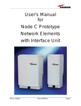
4.0 EQUIPMENT PHOTOGRAPHS
4.1 400 MHz Fiber Optic Fed Bi-Directional Amplifier

Wireless Innovations Group
2601 Telecom Parkway
Richardson, Texas 75082
400/800 MHz Fiber Optic & RF Fed Bi-Directional
Amplifier Operations / Maintenance Manual
DWG NO:
Error! Not a valid link.
Rev:
Error!
Not a
valid
link.
Date
:06/16/2004
Page:
13
of 63
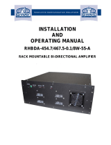
4.2 800 MHz Fiber Optic Fed Bi-Directional Amplifier

Wireless Innovations Group
2601 Telecom Parkway
Richardson, Texas 75082
400/800 MHz Fiber Optic & RF Fed Bi-Directional
Amplifier Operations / Maintenance Manual
DWG NO:
Error! Not a valid link.
Rev:
Error!
Not a
valid
link.
Date
:06/16/2004
Page:
14
of 63
5.0 MODULES
5.1 400 MHz EO Cell Amplifier Module (AE04A-D1264-001)
5.1.1 Description
This 2Watt, 483 - 487 MHz, class A Power Amplifier Module provides a nominal
52 dB of gain. It has 30 dB of gain adjustment range, which can be varied
electronically thru the front panel RS232 connector. Additionally, the module
has an internal Automatic Level Control (ALC) circuit, which can be set to limit
the maximum power level produced by the BDA. This module has an on board
RISC processor that provides optional alarming/status monitoring and
communications capabilities. The same module design is used for both the
Downlink and Uplink amplifier.
The amplifier modules contain high reliable RF parts to provide a long trouble-
free operating life. In the unlikely event of failure, the entire amplifier module
should be replaced.

Wireless Innovations Group
2601 Telecom Parkway
Richardson, Texas 75082
400/800 MHz Fiber Optic & RF Fed Bi-Directional
Amplifier Operations / Maintenance Manual
DWG NO:
Error! Not a valid link.
Rev:
Error!
Not a
valid
link.
Date
:06/16/2004
Page:
15
of 63
5.1.2 Specification
PARAMETER SPECIFICATION
Operating Frequency Range
483.1625 – 486.2375 MHz
Gain Typical 51.5 dB
Output Gain Adjustment
1
30 dB
Composite Output Power
≥
+33.5 dBm
Impedance 50 Ohms
VSWR 2:1
OIP3
2
≥
+ 47.5 dBm
Noise Power max. @ 51.5 dB Gain -111.5 dBm/Hz
DC Power + 48 VDC
Operating Temperature
-20
°
C to +60
°
C
Note:
1.Via Front Panel RS232 Connector.
2.Two-Tone Intermodulation: Measured two-output carriers of +23.5 dBm/C at
483.1625 MHz and 483.2375 MHz with 51.5 dB gain setting.
5.1.3 Photographs

Wireless Innovations Group
2601 Telecom Parkway
Richardson, Texas 75082
400/800 MHz Fiber Optic & RF Fed Bi-Directional
Amplifier Operations / Maintenance Manual
DWG NO:
Error! Not a valid link.
Rev:
Error!
Not a
valid
link.
Date
:06/16/2004
Page:
16
of 63

Wireless Innovations Group
2601 Telecom Parkway
Richardson, Texas 75082
400/800 MHz Fiber Optic & RF Fed Bi-Directional
Amplifier Operations / Maintenance Manual
DWG NO:
Error! Not a valid link.
Rev:
Error!
Not a
valid
link.
Date
:06/16/2004
Page:
17
of 63

Wireless Innovations Group
2601 Telecom Parkway
Richardson, Texas 75082
400/800 MHz Fiber Optic & RF Fed Bi-Directional
Amplifier Operations / Maintenance Manual
DWG NO:
Error! Not a valid link.
Rev:
Error!
Not a
valid
link.
Date
:06/16/2004
Page:
18
of 63
INTENTIONALLY LEFT BLANK

Wireless Innovations Group
2601 Telecom Parkway
Richardson, Texas 75082
400/800 MHz Fiber Optic & RF Fed Bi-Directional
Amplifier Operations / Maintenance Manual
DWG NO:
Error! Not a valid link.
Rev:
Error!
Not a
valid
link.
Date
:06/16/2004
Page:
19
of 63
INTENTIONALLY LEFT BLANK

Wireless Innovations Group
2601 Telecom Parkway
Richardson, Texas 75082
400/800 MHz Fiber Optic & RF Fed Bi-Directional
Amplifier Operations / Maintenance Manual
DWG NO:
Error! Not a valid link.
Rev:
Error!
Not a
valid
link.
Date
:06/16/2004
Page:
20
of 63
INTENTIONALLY LEFT BLANK
Page is loading ...
Page is loading ...
Page is loading ...
Page is loading ...
Page is loading ...
Page is loading ...
Page is loading ...
Page is loading ...
Page is loading ...
Page is loading ...
Page is loading ...
Page is loading ...
Page is loading ...
Page is loading ...
Page is loading ...
Page is loading ...
Page is loading ...
Page is loading ...
Page is loading ...
Page is loading ...
Page is loading ...
Page is loading ...
Page is loading ...
Page is loading ...
Page is loading ...
Page is loading ...
Page is loading ...
Page is loading ...
Page is loading ...
Page is loading ...
Page is loading ...
Page is loading ...
Page is loading ...
Page is loading ...
Page is loading ...
Page is loading ...
Page is loading ...
Page is loading ...
Page is loading ...
Page is loading ...
Page is loading ...
Page is loading ...
Page is loading ...
Page is loading ...
Page is loading ...
Page is loading ...
Page is loading ...
-
 1
1
-
 2
2
-
 3
3
-
 4
4
-
 5
5
-
 6
6
-
 7
7
-
 8
8
-
 9
9
-
 10
10
-
 11
11
-
 12
12
-
 13
13
-
 14
14
-
 15
15
-
 16
16
-
 17
17
-
 18
18
-
 19
19
-
 20
20
-
 21
21
-
 22
22
-
 23
23
-
 24
24
-
 25
25
-
 26
26
-
 27
27
-
 28
28
-
 29
29
-
 30
30
-
 31
31
-
 32
32
-
 33
33
-
 34
34
-
 35
35
-
 36
36
-
 37
37
-
 38
38
-
 39
39
-
 40
40
-
 41
41
-
 42
42
-
 43
43
-
 44
44
-
 45
45
-
 46
46
-
 47
47
-
 48
48
-
 49
49
-
 50
50
-
 51
51
-
 52
52
-
 53
53
-
 54
54
-
 55
55
-
 56
56
-
 57
57
-
 58
58
-
 59
59
-
 60
60
-
 61
61
-
 62
62
-
 63
63
-
 64
64
-
 65
65
-
 66
66
-
 67
67


Ask a question and I''ll find the answer in the document
Finding information in a document is now easier with AI
Related papers
-
 Andrew SelectAmp CDMA 800 User manual
-
 Andrew KUWMDL2400BDR User manual
-
 Andrew MR853D User manual
-
 Andrew MRx18 User manual
-
Andrew Wireless System ION-M7P User manual
-
 Andrew BCR-TFAHUS5 User manual
-
Andrew Wireless System XS5-MR171919 User manual
-
-
 Andrew Node C1943 User manual
-
Andrew Corporation S8L-100254MCPA User manual


Other documents
-
 Wave BDA-CELLB-2/2W-80-OCA User manual
-
G-Way Microwave / G-Wave Q8KPCSHW70A User manual
-
-
McIntosh D1100 Owner's manual
-
Radiant Communications VL2510-T User manual
-
Potter Guardian QR700 User manual
-
 G-Wave RHBDA-8W-55-A User manual
-
-
-
 TX RX Systems Signal Booster II 61-65-50 Series Operating instructions


