Page is loading ...

Repeaters
Node M and Node C
Network Elements
User's Manual
M0121A4A

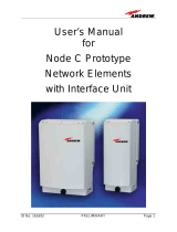
User’s Manual for Node M and Node C
Network Elements
Page 2 M0121A4A.doc
© Copyright 2010 CommScope, Inc.
All rights reserved.
Andrew Solutions is a trademark of CommScope, Inc.
All information contained in this manual has been revised thoroughly. Yet Andrew
Solutions accepts no liability for any omissions or faults.
Andrew Solutions reserves the right to change all hard- and software characteristics
without notice.
Names of products mentioned herein are used for identification purposes only and
may be trademarks and / or registered trademarks of their respective companies.
No parts of this publication may be reproduced, stored in a retrieval system,
transmitted in any form or by any means, electronical, mechanical photocopying,
recording or otherwise, without prior written permission of the publisher.
Andrew Wireless Systems GmbH, 05-February -2010

Page 3
TABLE OF CONTENTS
1. GENERAL 7
1.1. USED ABBREVIATIONS 7
1.2. HEALTH AND SAFETY WARNINGS 9
1.3. ABOUT ANDREW SOLUTIONS 11
1.4. INTERNATIONAL CONTACT ADDRESSES FOR WIG CUSTOMER SUPPORT 12
2. INTRODUCTION 15
2.1. PURPOSE 15
2.2. THE NODE M AND NODE C (NODE M/C) NETWORK ELEMENT 15
2.3. QUICK START CHECKLIST 16
3. CONNECTION SETUP 19
3.1. SETTING UP A LOCAL / LAN CONNECTION FROM LAPTOP / PC 19
3.2. SETTING UP NODE M/C REPEATER TO RUN AS A LAN ELEMENT 20
3.2.1. Prerequisites 20
3.2.2. Procedure 20
3.3. SETTING UP A REMOTE CONNECTION 21
4. INSTALLATION 23
4.1. MECHANICAL INSTALLATION 23
4.1.1. General 23
4.1.2. Wall Mounting Procedure 24
4.1.3. Pole Mounting Procedure 26
4.2. ELECTRICAL INSTALLATION 29
4.2.1. General 29
4.2.2. Grounding 30
4.2.3. Power Connection 31
4.2.4. Connection of the Antenna Cables 33
4.2.5. Opening the Cabinet - Mains Power Switch 34

User’s Manual for Node M and Node C
Network Elements
Page 4 M0121A4A.doc
5. FUNCTIONAL DESCRIPTION 37
5.1. DIGITAL ARCHITECTURE 37
5.2. FEATURES 39
5.2.1. Filters Node M 39
5.2.2. Filters Node C 39
5.2.3. Digital ICE (Digital Interference Cancellation Equipment) 40
5.2.4. VSWR (Voltage Standing Wave Ratio) 40
5.2.5. RSSI (Receive Signal Strength Indication) 41
5.2.6. Alarm Forwarding 41
5.2.7. Downlink Final Amplifier 42
5.2.8. Power Supply Unit 44
5.2.9. Modems 45
5.2.10. Digital Channel Module (DCM) 48
5.2.11. External Alarm Controller - EAC-Board 49
5.2.12. Battery Pack - Battery On/Off 55
5.2.13. UL and DL Duplexer 57
6. MAINTENANCE AND REPLACEMENT 59
7. ILLUSTRATIONS 59
7.1. CABINET DRAWING 59
7.2. LAYOUT OF THE NODE M/C 843 60
8. INDEX 61

Page 5
FIGURES AND TABLES
figure 3-1 Ethernet connector RJ45 19
figure 3-2 Pin connection 20
figure 3-3 Cable gland position 20
figure 4-1 Positions of drilling holes 24
figure 4-2 Wall mounting procedure 25
figure 4-3 Pole mounted units 26
figure 4-4 Back-to-back pole mounting 27
figure 4-5 Grounding bolt 30
figure 4-6 Power supply plug 31
figure 4-7 Mains connector of a Node M, exemplary 31
figure 4-8 Mains connector and antenna connections of a Node C, exemplary 31
figure 4-9 Front view of antenna connections from Node C, exemplary 33
figure 4-10 Front and top cover screws 34
figure 4-11 Position of mains power switch 35
figure 5-1 Configuration of a network element 37
figure 5-2 RF path of a Node C 843, exemplary 38
figure 5-3 Node M/C x37 MCPA DL final amplifier 42
figure 5-4 Node M 2143 and Node M 1943 MCPA DL final amplifier 42
figure 5-5 Node M/C 843 DL final amplifier 43
figure 5-6 Power supply, Node M/C x37 44
figure 5-7 Power supply, Node M/C x43 44
figure 5-8 Modem MC35 45
figure 5-9 Redwing modem (CDMA) 45
figure 5-10 Modem AnyDATA iPORT EMIII Dual / EM IV Dual 46
figure 5-11 Modem Raven XT 46
figure 5-12 Modem MTCBA-C-N9 46
figure 5-13 Cable from modem to donor duplexer 47
figure 5-14 Cable from modem to external modem antenna port; Node M 47
figure 5-15 Digital channel module, DL part 48
figure 5-16 Digital channel module, UL part 48
figure 5-17 EAC-board, installed 49
figure 5-18 Function of LEDs on the EAC-board 51
figure 5-19 Pin assignment 52

User’s Manual for Node M and Node C
Network Elements
Page 6 M0121A4A.doc
figure 5-20 External alarm clamps, installed 52
figure 5-21 Configuration of external alarm clamps 53
figure 5-22 External cable glands 53
figure 5-23 Summary alarm relay 54
figure 5-24 Relay contacts, alarm condition 54
figure 5-25 Battery pack, exemplary 55
figure 5-26 Battery pack installed and its connection to DCM 55
figure 5-27 Position of the battery disconnect button on the EAC-board 56
figure 5-28 Duplexer, UL IN 57
figure 5-29 Duplexer, DL IN 57
figure 5-30 Duplexers installed 57
figure 5-31 Duplexers installed, ceramic duplexer DL IN 58
figure 7-1 Cabinet of a Node M, respective Node C, exemplary 59
figure 7-2 Layout of the Node M/C 843, exemplary 60
table 1-1 List of international contact addresses....................................................... 13
table 4-1 Required length of thread-bolts ................................................................. 26
table 4-2 Components of pole mounting kit .............................................................. 27
table 4-3 Pin assignment of mains connector........................................................... 32
table 5-1 Pin assignment of relay contacts............................................................... 54

1 General
Page 7
1. GENERAL
1.1. USED ABBREVIATIONS
A/D Analogue to Digital Converter
AGC Automatic Gain Control
ALC Automatic Level Control
ARFCN Absolute Radio Frequency Channel Number
BCCH Broadcast Control Channel
BTS Base Transceiver Station
CDMA Code Division Multiple Access
D/A Digital to Analogue Converter
DAS Distributed Antenna System
DCM Digital Channel Module
DHCP Dynamic Host Configuration Protocol
D-ICE Digital Interference Cancellation Equipment
DL Downlink
DSP Digital Signal Processor
EAC External Alarm Controller
EDGE Enhanced Data Rates for GSM Evolution
ESD Electrostatic Discharge
ETS European Telecommunication Standard
ETSI European Telecommunication Standards Institute
FCC Federal Communications Commission
FRU Field Replaceable Unit
GPRS General Packet Radio Service
GSM Global System for Mobile Communication
HID Hardware Inventory Data
HSN Hopping Sequence Number
I
2
C Bus Inter Integrated Circuit Bus (Philips)
ICE Interference Cancellation Equipment
ID No Identification Number
LAN Local Area Network
LED Light Emitting Diode
LMT Local Maintenance Terminal
LNA Low Noise Amplifier
LO Local Oscillator
MAIO Mobile Allocation Index Offset
MCPA Multi Carrier Power Amplifier
Ncm Newton centimeter
NSB Network Supervision Box
OFDM Orthogonal Frequency Division Multiplex
OMC Operation and Maintenance Centre
PA Power Amplifier
PAMR Public Access Mobile Radio
PPP Point-to-Point Protocol
PSTN Public Switched Telephone Network
RF Radio Frequency

User’s Manual for Node M and Node C
Network Elements
Page 8 M0121A4A.doc
RLP Radio Link Protocol
RSCP Received Signal Code Power
RSSI Receive Signal Strength Indication
RTC Real Time Clock
RX Receiver
SCPA Single Carrier Power Amplifier
SDA Serial Data
SMS Short Message Service
SNMP Simple Network Management Protocol
TS Transmitter
UE User Equipment
UL Uplink
UMTS Universal Mobile Telecommunication System
UPS Uninterruptible Power Supply
UTC Universal Time Coordinate
UTRA UMTS terrestrial radio access
VCO Voltage Controlled Oscillator
VSWR Voltage Standing Wave Ratio
WCDMA Wide-band Code Division Multiple Access

1 General
Page 9
1.2. HEALTH AND SAFETY WARNINGS
1. Only suitably qualified people are allowed to work on this unit and only after
becoming familiar with all safety notices, installation, operation and maintenance
procedures contained in this manual.
2. Read and obey all the warning labels attached to the unit. Make sure that the
warning labels are kept in a legible condition and replace any missing or
damaged labels.
3. Obey all general and regional installation and safety regulations relating to work
on high voltage installations, as well as regulations covering correct use of tools
and personal protective equipment.
4. Keep operating instructions within easy reach and make them available to all
users.
5. It is the responsibility of the network provider to implement prevention measures
to avoid health hazards which may be associated to radiation from the antenna(s)
connected to the unit.
6. IMPORTANT NOTE: To comply with FCC RF exposure compliance requirements,
the following antenna installation and device operating configurations must be
satisfied: A separation distance of at least 400 cm must be maintained between
the antenna of this device and all persons. RF exposure compliance may need to
be addressed at the time of licensing, as required by the responsible FCC
Bureau(s), including antenna co-location requirements of 1.1307(b)(3). Maximum
permissible antenna gain is 17 dBi.
7. Make sure, access is restricted to qualified personnel.
8. Only licence holders for the respective frequency range are allowed to operate
this unit.
9. Use this equipment only for the purpose specified by the manufacturer. Do not
carry out any modifications or fit any spare parts which are not sold or
recommended by the manufacturer. This could cause fires, electric shock or other
injuries.
10. Due to power dissipation, the network element may reach a very high
temperature. Do not operate this equipment on or close to flammable materials.
11. Before opening the unit, disconnect mains.
12. ESD precautions must be observed! Before commencing maintenance work, use
the available grounding system to connect ESD protection measures.

User’s Manual for Node M and Node C
Network Elements
Page 10 M0121A4A.doc
13. This unit complies with European standard EN60950.
14. Make sure the network element settings are according to the intended use (see
also product information of manufacturer) and regulatory requirements are met.
15. Although the network element is internally protected against overvoltage, it is
strongly recommended to earth the antenna cables close to the network
element’s antenna connectors for protection against atmospheric discharge.

1 General
Page 11
1.3. ABOUT ANDREW SOLUTIONS
Andrew Wireless Systems GmbH based in Buchdorf/ Germany, is a leading
manufacturer of coverage equipment for mobile radio networks, specializing in low
cost, high performance, RF and optical repeaters. Our optical distributed networks
and RF repeater systems provide coverage for every application: outdoor use, indoor
installations, tunnels, subways and many more.
Andrew Wireless Systems GmbH belongs to the Wireless Innovations Group (WIG).
Being a part of Andrew Solutions, WIG has unparalleled experience in providing RF
coverage and capacity solution for wireless networks in both indoor and outdoor
environment.
Andrew Solutions, a CommScope Company, is the foremost supplier of one-stop,
end-to-end radio frequency (RF) solutions. Our products are complete solutions for
wireless infrastructure from top-of-the-tower base station antennas to cable systems
and cabinets, RF site solutions, signal distribution, and network optimization.
Andrew Solutions has global engineering and manufacturing facilities. In addition, it
maintains field engineering offices throughout the world.
We operate a quality management system in compliance with the requirements of
ISO 9001. All equipment is manufactured using highly reliable material. In order to
ensure constant first-rate quality of the products, comprehensive quality monitoring is
conducted at all fabrication stages. Finished products leave the factory only after a
thorough final acceptance test, accompanied by a test certificate guaranteeing
optimal operation.
The declaration of conformity for the product is available upon request from the local
sales offices or from Andrew Solutions directly.
To make the utmost from this unit, we recommend you carefully read the instructions
in this manual and commission the unit only according to these instructions.
For technical assistance and support, contact the local office or Andrew Solutions
directly at one of the following addresses listed in the next chapter.

User’s Manual for Node M and Node C
Network Elements
Page 12 M0121A4A.doc
1.4. INTERNATIONAL CONTACT ADDRESSES FOR WIG CUSTOMER
SUPPORT
Wireless Innovations Group (WIG)
Americas:
Canada United States
Andrew Solutions Canada
Andrew Solutions,
Andrew LLC, A CommScope Company
Mail
620 North Greenfield Parkway
Garner, NC 27529
U.S.A.
Mail
620 North Greenfield Parkway
Garner, NC 27529
U.S.A.
Phone
+1-905-878-3457 (Office)
+1 416-721-5058 (Mobile)
Phone
+1-888-297-6433
Fax
+1-905-878-3297
Fax
+1-919-329-8950
E-mail
WIsupport.us@andrew.com
E-mail WIsupport.us@andrew.com
Brazil & South America
Mexico, Central America &
Caribbean region
Andrew Solutions,
A CommScope Company
Andrew Solutions Mexico
Mail
Av. Com. Camilo Julio 1256
Predio B
Zonal Industrial CP 597
Sorocaba SP 18086-000
Brazil
Mail
Monte Elbruz 124-402A
Col. Palmas Polanco 11560
Mexico, D.F.
Mexico
Phone
+ 55-15-9104-7722
Phone
+ 52-55-1346-1900 (Office)
+52-1-55-5419-5260 (Mobile)
Fax
+ 55-15-2102-4001
Fax
+52-55-1346-1901
E-mail [email protected]
E-mail [email protected]
APAC Countries:
China Australia
Andrew Solutions Hong Kong
Andrew Corporation (Australia)
LLC Pty Ltd.
Mail
Room 915
Chevalier Commercial Centre
8 Wang Hoi Rd
Kowloon Bay SAR
Hong Kong
Mail
Unit 1
153 Barry Road
Campbellfield
VIC 3061
Australia
Phone
+852-310-661-00
Phone
+613-9300-7969
Fax
+852-2751-7800
Fax
+613-9357-9110
E-mail WISupport.china@andrew.com
E-mail [email protected]

1 General
Page 13
Europe:
United Kingdom France
Andrew Solutions UK Ltd Andrew Solutions France
Mail
Unit 15, Ilex House
Mulberry Business Park
Fishponds Road
Wokingham Berkshire
RG41 2GY
England
Mail
28, Rue Fresnel
Z.A Pariwest
BP 182
78313 Coignières Cedex
France
Phone
+44-1189-366-792
Phone
+33 1 30 05 45 50
Fax
+44-1189-366-773
Fax
+33 1 34 61 13 74
E-mail [email protected]
E-mail [email protected]
Germany Czech Republic
Andrew Wireless Systems GmbH
Andrew Solutions Czech Republic
C-Com, spol. s r.o
Mail
Industriering 10
86675 Buchdorf
Germany
Mail
U Moruší 888
53006 Pardubice
Czech Republic
Phone
+49-9099-69-0
Phone
+420-464-6280-80
Fax
+49-9099-69-930
Fax
+420-464-6280-94
E-mail [email protected]
E-mail [email protected]
Austria Switzerland
Andrew Wireless Systems (Austria)
GmbH
Andrew Wireless Systems AG
Mail
Weglgasse 10
Wien-Schwechat 2320
Austria
Mail
Tiergartenweg 1
CH-4710 Balsthal
Switzerland
Phone
+43-1706-39-99-10
Phone
+41-62-386-1260
Fax
+43-1706-39-99-9
Fax
+41-62-386-1261
E-mail WIsupport.austria@andrew.com
E-mail [email protected]
Italy Spain & Portugal
Andrew Wireless Systems S.r.l., Faenza,
Italy
Andrew Solutions España S.A.
Mail
Via de Crescenzi 40
Faenza 48018
Italy
Mail
C/ Salvatierra, 5 - 3
a
pt.
28034 Madrid
Spain
Phone
+39-0546-697111
Phone
+34-91-745-20 40
Fax
+39-0546-682768
Fax
+34-91-564-29 85
E-mail WIsupport.i[email protected]
E-mail [email protected]
table 1-1 List of international contact addresses

User’s Manual for Node M and Node C
Network Elements
Page 14 M0121A4A.doc
For your notes:

2 Introduction
Page 15
2. INTRODUCTION
2.1. PURPOSE
Wireless communication systems provide a two-way information transfer (voice and
data) between a base station and multiple mobiles within a given area.
Environmental variables such as physical structures both man-made (buildings) and
natural (mountains) attenuate signals in the transmission path, which reduce the
transport signal’s strength. This attenuation leads to a reduction in quality and data
rate and eventually prohibits the system’s use entirely. The Node M and Node C are
specifically designed to extend coverage, enhance quality, and increase air-interface
capacity.
In the downlink (DL), the Node M and Node C picks up signals coming from the base
station, filters them, amplifies them, and retransmits them to the mobile. In the uplink
(UL), it picks up signals from the mobile, filters them, amplifies them, and retransmits
them to the base station. The Node M and Node C constantly monitors the quality of
the signals passing through it, while simultaneously electronically decreasing
isolation requirements.
2.2. THE NODE M AND NODE C (NODE M/C) NETWORK ELEMENT
Node M and Node C are primary network elements, capable of enhancing up to 20
MHz of continuous spectrum. Their primary function is to increase the signal strength
between multiple mobiles and a base station in areas where basic voice or high-
speed data transmission is not available. They may be used for basic coverage,
signal reinforcement, and cell shaping, which can increase a network’s coverage
area, data rate, and capacity.
The Node M is a dedicated UMTS device, but the Node C operates with CDMA
technology. However, several enhancers operating at different frequencies and
technologies may share the same hardware (cables and antennas) via a crossband
coupler.
The Node M or Node C may be set-up locally or remotely. A circuit switch or packet
data modem may be connected to an integrated controller. This provides the network
management system with on-demand, alarm generated, or heartbeat monitoring via
the always-connected packet features. The Node M and Node C have features and
functions that may be monitored and changed by the operators via a web-based
browser remotely or locally, or via the SNMP based OMC software platform. The
graphical interfaces of Node M and Node C provide a setup menu including a setup
wizard which allows both setup and monitoring capability without any equipment
required apart from a laptop or PC.
The Node M and Node C network elements are self-diagnosing, self-adaptive, and
virtually maintenance-free.
In the following, the expression Node M/C stands for Node M and Node C.

User’s Manual for Node M and Node C
Network Elements
Page 16 M0121A4A.doc
2.3. QUICK START CHECKLIST
Read the health and safety warnings in chapter 1.2 Health and Safety Warnings.
Setting up the Node M/C is quick and easy. The following step-by-step
procedure provides a quick overview for a correct setup and optimization.
a. Required Equipment
Node M or Node C
donor antenna
coverage antenna(s) or DAS
coaxial feeder cable
connectors (RF, mains)
laptop (Win XP or Win 2000) with connection and mains cable
standard Ethernet cable (CAT5) (see chapter 3 Connection Setup)
b. Required Information
Make sure to have the following information at hand:
important on-site conditions (e.g. BTS location, mains supply, etc.)
channels to be enhanced/ amplified
pilot power to total power ratio
data of mandatory fields of Connectivity and Upload page see user's
manual for Node software.
c. Procedure
1. Install the donor (linear polarized recommended) and coverage antennas.
2. Install the feeder cable from the Node M/C to the antennas.
3. Install the Node M/C (see chapter 4.1 Mechanical Installation)
) Note: Take care to ground the unit correctly as instructed in chapter 4.2.2
Grounding.
4. Connect power and the antenna feeder cables to the Node M/C.
5. Open the Node M/C as described in chapter 4.2.5 Opening the Cabinet -
Mains Power Switch.
6. Setup the connection computer (see chapter 3 Connection Setup and software
manual).

2 Introduction
Page 17
7. Login to the unit and follow the installation wizard option for easy installation.
a. Optimize the donor antenna performance (see software manual).
b. To select the channels for enhancement, choose between the
“Measurement Assisted Channel Assignment” or “Unassisted
Channel Assignment” from the Setup Wizard page (see software
manual).
c. Enter the pilot power to total power ratio of the donor Base Station.
d. Enter the desired output power in the downlink.
e. Enter the relative uplink gain and click the “Program” button.
f. Select the “Connectivity and Upload” button, to setup the modem (if
applicable) and to enter data in the other user fields (see software
manual).
g. Select the “Technician Setup” button (see software manual), to
change additional system settings, e.g. ICE, H.R. Filter, Diversity;
the “Technician Setup” is also accessible from the home page.
8. The Node M/C setup is complete.
9. Open the “Save Configuration to Laptop” menu for record keeping purposes.
10. Unplug the computer, close the Node M/C and tighten all screws.
) Note: To do a power cycle, disconnect the battery backup by pushing the
battery disconnect button on the EAC-board; see chapter
5.2.12 Battery Pack - Battery On/Off.

User’s Manual for Node M and Node C
Network Elements
Page 18 M0121A4A.doc
For your notes:

3 Connection Setup
Page 19
3. CONNECTION SETUP
3.1. SETTING UP A LOCAL / LAN CONNECTION FROM LAPTOP / PC
figure 3-1 Ethernet connector RJ45
2
1
Ethernet connector - LEDs
After the connection is made properly, the red and green LEDs near the Node C
network connector will flash.
No Colour Explanation
1 Yellow
LED illuminates when a packet is transmitted by the DCM2 DL
module.
2 Green LED illuminates when a packet is received by the DCM2 DL module.
A standard CAT5 Ethernet cable is supplied to set up a local connection. Open the
Node and plug the cable in the Ethernet connector RJ45 of the EAC-board.
To setup a LAN connection follow the description in the next chapter. A cable is not
provided.

User’s Manual for Node M and Node C
Network Elements
Page 20 M0121A4A.doc
3.2. SETTING UP NODE M/C REPEATER TO RUN AS A LAN ELEMENT
3.2.1. Prerequisites
Use the Local Area Network (LAN) mode to activate DHCP clients or to assign a
static IP address to the Node M/C.
) Note: Before it is possible to configure the LAN settings alarm connectors
7 and 8 must be connected in order to activate External Alarm 1,
figure 3-2 Pin connection.
A local connection via laptop or PC cannot be setup as long as alarm connectors 7
and 8 are connected.
) Note: In the software, LAN Information settings will be activated, if the
main connectivity is set to LAN. Please refer to the software
manual.
For the connection of the Node to the LAN network please use the same type /
category of Ethernet cable as for the connection of the computer to the LAN network.
3.2.2. Procedure
1. Switch off repeater and connect Pin 7 and Pin 8 of the External Alarm connector.
Pin
Pin
2 n.c. 1 n.c.
4 GROUND 3 EXT_ALARM_3
6 GROUND 5 EXT_ALARM_2
8 GROUND 7 EXT_ALARM_1
10 PSTN_1_EXTERNAL 9 PSTN_1_INTERNAL
12 PSTN_2_EXTERNAL 11 PSTN_2_INTERNAL
14 GROUND 13 SUMMARY ALARM, LED GREEN
16 GROUND 15 SUMMARY ALARM, LED RED
figure 3-2 Pin connection
2. Switch on repeater
3. Put an Ethernet CAT5 cable
(recommended cable diameter is
4 - 6 mm) through one of the PG7
cable glands into the Node.
figure 3-3 Cable gland position
2 1
15
16
/