Page is loading ...

OPERATION AND MAINTENANCE MANUAL
For the
MODEL 2400
DISTRIBUTION LINE AMPLIFIER
MANUAL NO. 385700-4006
REVISION 6
The information set forth in this document and all rights in and to inventions
disclosed herein, and patents which might be granted thereon disclosing,
employing or covering the materials, methods, techniques or apparatus
described herein are the exclusive property of Andrew Corporation.
This document is an operation and maintenance manual. No disclosure or
reproduction of the information or drawings shall be made of any other
purpose without the prior written consent of Andrew. Use of the information
contained herein to fabricate or assemble any item in whole or in part is
expressly prohibited
.
2601 Telecom Parkway, Richardson, Texas 75082-3521
TEL (972) 952 9700 FAX (972) 952-0000

385700-4006-006 SAFETY SUMMARY
Document use is restricted to that described on cover A
SAFETY SUMMARY
High voltage is used in the operation of
this equipment. Death on contact may
result, if personnel fail to observe the
following safety precautions:
• Do not be misled by the term “Low Voltage.” Potentials as low as 50 Volts may cause
death under adverse conditions.
• Do not crush, puncture, disassemble or otherwise mutilate batteries. Leaking batteries
can cause serious damage to equipment and injury to personnel.
• Do not remove covers or access plates on the equipment, unless you are authorized to do so.
• Do not work on electronic equipment unless there is another person nearby who is familiar
with the operation of the equipment and is trained in administering first aid.
• Whenever possible, disconnect the equipment from the power source before beginning
maintenance.
• To prevent electrical shock or damage to the equipment, do not operate it until you
thoroughly understand the operation and function of all controls, indicators, and
connectors.
• Turn off all power to the equipment before replacing any fuses.
FIRST AID
In case of electrical shock:
• Do not try to pull or grab the individual.
• If possible, turn off the electrical power.
• If you cannot turn off the electrical power, pull, push, or lift the person to safety using a dry
wooden pole, a dry rope, or some other insulating material.
• Send for help as soon as possible.
• After the injured person is no longer in contact with the source of electrical shock, move
the person a short distance away and immediately administer first aid and artificial
resuscitation as required.

385700-4006-006 LIST OF ABBREVIATIONS AND ACRONYMS
Document use is restricted to that described on cover B
The Distribution Line Amplifier is an unlicensed device operating
under the conditions of FCC part 15 regulations. This equipment
is intended to be installed and operated by professional parties.
It is the responsibility of those parties to insure that the
equipment is operated in compliance with the applicable FCC
part 15 specifications.
LIST OF ABBREVIATIONS AND ACRONYMS
All abbreviations/acronyms used in this
manual, other than those listed on this
page, are used per MIL-STD-12D.
BDR Base Data Radio
USER Communications-Based Train Control
DLA Distribution Line Amplifier
ESDS Electrostatic Discharge Sensitive
FWD Forward
LRU Line Replaceable Unit
MDR Mobile Data Radio
PC Personal Computer
RCS Radio Communication Subsystem
RF Radio Frequency
RVS Reverse
SSR Spread Spectrum Radio
N
O
TE
WARNING

385700-4006-006 LIST OF REFERENCE DOCUMENTS
Document use is restricted to that described on cover C
LIST OF REFERENCE DOCUMENTS
Andrew Catalog 37 (or latest version)
Drawings:
Assembly, Line Amplifier 385700-4000

385700-4006-006 TABLE OF CONTENTS
Document use is restricted to that described on cover i
TABLE OF CONTENTS
CHAPTER 1............................................................................................................................................ 1-4
1.1 GENERAL MANUAL INFORMATION........................................................................................ 1-4
1.2 PREPARATION FOR STORAGE OR SHIPMENT.................................................................... 1-4
1.2.1Storage.............................................................................................................................. 1-4
1.2.2Shipment........................................................................................................................... 1-4
1.3 DESCRIPTION OF EQUIPMENT.............................................................................................. 1-5
1.3.1Type of Equipment............................................................................................................ 1-5
1.3.2Purpose of the Equipment................................................................................................. 1-5
1.4 LOCATIONS AND DESCRIPTIONS OF MAJOR COMPONENTS........................................... 1-6
1.4.1Distribution Line Amplifier Principles of Operation............................................................ 1-6
1.4.2Distribution Line Amplifier Major Components.................................................................. 1-9
1.5 EQUIPMENT CHARACTERISTICS......................................................................................... 1-10
1.5.1Power and Utility Requirements...................................................................................... 1-10
1.5.2Environmental Information .............................................................................................. 1-10
CHAPTER 2............................................................................................................................................ 2-1
2.1 INSTALLING THE DISTRIBUTION LINE AMPLIFIER EQUIPMENT........................................ 2-1
2.1.1Unpacking and Inspection................................................................................................. 2-1
2.1.2Proper Installation of Units................................................................................................ 2-1
2.2 INTERCONNECTIONS.............................................................................................................. 2-1
2.2.1Forward Direction Configuration Interconnection.............................................................. 2-1
2.2.2Reverse Direction Configuration Interconnection.............................................................. 2-2
2.3 CABLE AND GROUND REQUIREMENTS................................................................................ 2-2
2.3.1Mating Connector Pin-outs................................................................................................ 2-5
2.4 DISTRIBUTION LINE AMPLIFIER COMPONENT JACK LOCATIONS.................................... 2-7
2.5 PREPARATION FOR USE........................................................................................................ 2-8
2.5.1Distribution Line Amplifier Setup....................................................................................... 2-8
2.5.2Distribution Line Amplifier Initial Operational Adjustments................................................ 2-9
2.5.2.1 Input AC Power............................................................................................................. 2-9
2.5.2.2 Power Amplifier (PA) Channel (Channel 1) ................................................................. 2-9
2.5.2.2.1 PA Equipment Setup............................................................................................ 2-9
2.5.2.2.2 PA Input Alarm Adjustment................................................................................ 2-10
2.5.2.2.3 PA Output Adjustment........................................................................................ 2-11
2.5.2.2.4 PA Output Alarm Adjustment............................................................................. 2-11
2.5.2.3 Low Noise Amplifier (LNA) Channel (Channel 2)........................................................ 2-12
2.5.2.3.1 LNA Adjustment Equipment Setup..................................................................... 2-12
2.5.2.3.2 LNA Output Adjustment ..................................................................................... 2-13
2.5.2.3.3 LNA Output Alarm Adjustment........................................................................... 2-14
2.5.3Operational Check-Out ................................................................................................... 2-14
2.5.3.1 Forward PA Channel Verification................................................................................ 2-14
2.5.3.1.1 PA Output Level Verification .............................................................................. 2-14
2.5.3.1.2 PA Input Signal Alarm........................................................................................ 2-15
2.5.3.1.3 PA Output Signal Alarm ..................................................................................... 2-15
2.5.3.2 Forward LNA Channel Verification.............................................................................. 2-16
2.5.3.2.1 LNA Output Level Verification............................................................................ 2-16
2.5.3.2.2 LNA Output Signal Alarm................................................................................... 2-16
2.5.3.3 Reverse PA Channel Verification................................................................................ 2-16
2.5.3.3.1 PA Output Level Verification .............................................................................. 2-16
2.5.3.3.2 PA Input Signal Alarm........................................................................................ 2-17
2.5.3.3.3 PA Output Signal Alarm ..................................................................................... 2-17
2.5.3.4 Reverse LNA Channel Verification ............................................................................. 2-17
2.5.3.4.1 LNA Output Level Verification............................................................................ 2-17
2.5.3.4.2 LNA Output Signal Alarm................................................................................... 2-17

385700-4006-006 TABLE OF CONTENTS
Document use is restricted to that described on cover ii
CHAPTER 3............................................................................................................................................ 3-1
3.1 WIRING PROTECTION AND GROUNDING............................................................................. 3-1
3.2 STARTUP AND SHUTDOWN PRODECURES......................................................................... 3-2
3.2.1DLA Startup....................................................................................................................... 3-2
3.2.2Normal Operation.............................................................................................................. 3-2
3.2.3Shutdown .......................................................................................................................... 3-2
CHAPTER 4............................................................................................................................................ 4-1
4.1 TROUBLESHOOTING............................................................................................................... 4-1
4.2 CORRECTIVE MAINTENANCE................................................................................................ 4-2
4.2.1Remove and Replace DLA................................................................................................ 4-2
4.3 TEST PROCEDURES ............................................................................................................... 4-4
4.3.1Inoperative Distribution Line Amplifier............................................................................... 4-4
4.3.1.1 Input Power Verification................................................................................................ 4-4
4.3.1.2 RADIAX
Alarm Asserted............................................................................................. 4-5
4.3.1.3 Amplifier Alarm Asserted.............................................................................................. 4-5
4.3.1.3.1 Loss of PA Input Signal........................................................................................ 4-5
4.3.1.3.2 PA Module Failure................................................................................................ 4-5
4.3.1.3.3 Loss of Pilot Tone Signal...................................................................................... 4-6
4.3.1.3.4 LNA Module Failure.............................................................................................. 4-6
CHAPTER 5............................................................................................................................................ 5-1
5.1 PARTS LIST .............................................................................................................................. 5-1
CHAPTER 6............................................................................................................................................ 6-1
CHAPTER 7............................................................................................................................................ 7-1

385700-4006-006 TABLE OF CONTENTS
Document use is restricted to that described on cover iii
LIST OF FIGURES
Figure 1-1 Distribution Line Amplifier (4 port).......................................................................1-6
Figure 1-2 DLA Block Diagram ............................................................................................1-8
Figure 1-3 DLA Internal View................................................................................................1-9
Figure 2-1 DLA Forward Direction Interconnect Diagram.....................................................2-3
Figure 2-2 DLA Forward Direction Interconnect Diagram......................................................2-4
Figure 2-3 DLA Input VAC Pin-outs ......................................................................................2-5
Figure 2-4 DLA ALARM/CONTROL Port Pin-outs................................................................2-6
Figure 2-5 DLA Assembly Jack Locations............................................................................2-7
Figure 2-6 PA Output Level Test Setup ...............................................................................2-9
Figure 2-7 PA Module Outline............................................................................................2-10
Figure 2-8 LNA Module Outline..........................................................................................2-12
Figure 2-9 LNA Output Level Test Set Up..........................................................................2-13
Figure 3-1 DLA Connector Panel Layout..............................................................................3-1
Figure 4-1 Remove and Replace DLA..................................................................................4-3
Figure 6-1 DLA Mechanical Outline .....................................................................................6-1
LIST OF TABLES
Table 1-1 – DLA Part Numbers.............................................................................................1-5
Table 1-2 Distribution Line Amplifier Specifications............................................................1-11
Table 2-1 – Forward Direction RF Port Functions.................................................................2-3
Table 2-2 Reverse Direction RF Port Functions....................................................................2-4
Table 4-1 DLA Fault Isolation...............................................................................................4-1
Table 4-2 Test Equipment....................................................................................................4-4
Table 5-1 Vendors...............................................................................................................5-1
Table 5-2 Parts List..............................................................................................................5-2

385700-4006-006 INTRODUCTION
Document use is restricted to that described on cover 1-4
CHAPTER 1
INTRODUCTION
1.1 GENERAL MANUAL INFORMATION
This manual contains instructions for the operation, maintenance, and support of the
Distribution Line Amplifier (DLA) assembly. This manual describes the amplifier assembly in
detail. It provides the necessary information for qualified technical personnel to install, repair,
and maintain the Distribution Line Amplifier to the line replaceable unit (LRU).
This manual is divided into seven chapters, which consist of sections to describe the
information or procedures in detail. The five chapters are as follows:
• Chapter 1 outlines the contents of this manual and provides a basic equipment
description of the Distribution Line Amplifier.
• Chapter 2 provides preparation for use and installation information.
• Chapter 3 provides operating procedures for the equipment.
• Chapter 4 provides preventive and corrective maintenance of the Distribution Line
Amplifier assembly.
• Chapter 5 contains a vendor list and parts list for procurement of replacement
parts.
• Chapter 6 provides mechanical outline information
• Chapter 7 contains a schematic of a test fixture for the Alarm/Control interface.
1.2 PREPARATION FOR STORAGE OR SHIPMENT
The following paragraphs describe guidelines for long term storage and the shipment of the
equipment.
1.2.1 Storage
Before storage, wrap the equipment in static shielding bubble wrap. Bubble wrap protects
internal electrostatic discharge sensitive (ESDS) assemblies, external panels, and connectors.
Place wrapped equipment in the original shipping containers and seal. Store in a cool dry
place, away from the elements.
1.2.2 Shipment
Ship equipment in the original shipping containers or in a container that provides sufficient
protection for ESDS equipment. Pack the equipment in a manner that provides protection for
all external switches and mountings, because these items are most vulnerable to damage
during shipment.

385700-4006-006 INTRODUCTION
Document use is restricted to that described on cover 1-5
1.3 DESCRIPTION OF EQUIPMENT
The Radio Communications Network consists of Base and Mobile Radio Communication
Systems (RCS) and a Wayside Antenna System. The Distribution Line Amplifier (DLA) is part
of the distributed Wayside Antenna System based on leaky-feeder cable RADIAX
®
. DLA’s are
used to compensate for attenuation losses in the cable by providing bi-directional amplification
of signals. The DLA also includes a direction control signal and status signals to monitor
amplifier operation.
1.3.1 Type of Equipment
The DLA is a FCC approved bi-directional amplifier that is used with spread spectrum
transceivers that operate in the ISM 2400-2483.5 MHz frequency band. The 4 versions of the
DLA are shown in Table 1-1. The models differ in the number of RF ports and the type of
control interface.
Part Number Description
385700-4000-001 4 port amplifier with LONWorks™ Interface
385700-4000-002 4 port amplifier with dry contact Interface
385700-4000-003 2 port amplifier with LONWorks™ Interface
385700-4000-004 2 port amplifier with dry contact Interface
Table 1-1 – DLA Part Numbers
1.3.2 Purpose of the Equipment
The Distribution Line Amplifier provides selective frequency range amplification of both a
forward (downlink) and reverse (uplink) direction signals in RADIAX
®
cable. Forward is
defined as the direction of RF energy from the BDR at the wayside to the MDR. Reverse
direction is defined as the direction of RF energy from the MDR to the BDR. The signals that
appear on the line amplifier RF ports are determined by the USER controlled direction signal.

385700-4006-006 INTRODUCTION
Document use is restricted to that described on cover 1-6
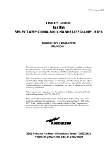
1.4 LOCATIONS AND DESCRIPTIONS OF MAJOR COMPONENTS
Refer to Figure 1-1 Distribution Line Amplifier (4 port) for a view of the external connections
of the 4 port DLA. The 2 port DLA does not include J5 or J6. The mechanical outline of the
DLA is given in CHAPTER 6. The following paragraphs contain the description of the
Distribution Line Amplifier.
Figure 1-1 Distribution Line Amplifier (4 port)
1.4.1 Distribution Line Amplifier Principles of Operation
The bi-directional Distribution Line Amplifier operates within two sub-regions of the 2400 –
2483.5 MHz ISM band. It filters and amplifies at the BDR center frequency of 2416.64 MHz.
in one direction (FWD) and at the MDR center frequency of 2467.86 MHz in another direction
(RVS).
The RF signal at each amplifier is routed through a diplexer (filter) to divide the signal into two
paths: forward and reverse. The DLA has a direction control switch which changes the signal
path to the opposite direction upon the command from the user control equipment network
data interface via the alarm and control interface board. The internal status of the DLA is
monitored by the Amplifier Alarm Detectors. The status signals are sent to the USER control
equipment network data interface via the alarm and control interface.
The BDR path, also referred to as the PA channel or channel 1, contains a power amplifier.
The maximum PA output of the 4 port DLA is < +27 dBm per output port. The PA output port
of the 2 port DLA is < +30 dBm. The PA channel maintains a constant output power over a
user adjustable range. See Table 1-2 Distribution Line Amplifier Specifications for the input
range over which the output power is adjustable. The PA channel also contains an input

385700-4006-006 INTRODUCTION
Document use is restricted to that described on cover 1-7
power level alarm as well as an output power alarm. The alarm levels are user adjustable.
The MDR path is also referred to as the LNA channel or channel 2. The LNA channel is
referenced to a pilot tone within the Distribution Line Amplifier. The pilot tone is used (1) to
set the gain of the LNA channel and (2) to provide a method of detecting a faulty LNA module.
The LNA channel gain is user adjustable. The maximum LNA gain is +27 dB for the 4 port
DLA per output port and +30 dB for the 2 port DLA. See Table 1-2 Distribution Line Amplifier
Specifications for the range over which the gain is adjustable. Under normal operation, the
input signal is expected to be lower (nominally 10 dB) than the pilot tone.
The PA channel input alarm is used to detect a loss of input signal due to cable breakage, etc.
The PA channel output alarm and the LNA channel output alarm are combined to indicate an
amplifier failure.
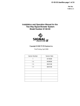
Refer to Figure 1-2 DLA Block Diagram, for bi-directional amplifier major component
identification.

385700-4006-006 INTRODUCTION
Document use is restricted to that described on cover 1-8
Figure 1-2 DLA Block Diagram
-10 dBm
Radiax
Alarm & Control
Interface Board
24V Lightning
Protectors
RF Lightning
Protection
Transfer
Relay
RF Lightning
Protection
Radiax
Diplexer
Direction Status
Direction Control
PA
Radiax Alarm
Detector
PA Alarm
Detector
+12 VDC
LNA
LNA Alarm
Detector
Pilot Tone
Generator
+12 VDC
Diplexer
A
larm & Control
Connections
AC-DC
Power Supply
AC
Lightning
Protection
87-265 VAC
+12 VDC
USER Control Equipment

385700-4006-006 INTRODUCTION
Document use is restricted to that described on cover 1-9
1.4.2 Distribution Line Amplifier Major Components
Refer to Figure 1-3 DLA Internal View for locations of major DLA components. The test point
locations, Pilot Tone Output J3 on the Pilot Tone Board and Alarm and Control Interface
Board Test Points J4, shown in
Figure 1-3 are used for initial DLA adjustments and referenced later in this manual in section
2.5.
Figure 1-3 DLA Internal View
Refer to section 2.5.1, Distribution Line Amplifier Setup, for PA and LNA outline views and
controls.
Lightning Protection Module
J1
J8
J5
J2
J9
J7
J6J3 J4
J2
J1

385700-4006-006 INTRODUCTION
Document use is restricted to that described on cover 1-10
1.5 EQUIPMENT CHARACTERISTICS
Refer to Table 1-2 Distribution Line Amplifier Specifications. The table contains the
specifications for the DLA. The table includes characteristics and specifications in three
categories: technical, environmental, and physical.
1.5.1 Power and Utility Requirements
The DLA operates across an AC input range of 87 to 265 VAC. No user adjustment is
required.
1.5.2 Environmental Information
The DLA assembly is designed for above and below ground environments. Refer to Table 1-2
Distribution Line Amplifier Specifications, for more detailed information.
The DLA is housed in a NEMA4X enclosure. It is intended for indoor or outdoor use to
provide a degree of protection against corrosion, windblown dust and rain, splashing water,
and hose-direct water; undamaged by the formation of ice on the enclosure. The NEMA4X
enclosure is manufactured from 16 gauge Type 304 stainless steel.

385700-4006-006 INTRODUCTION
Document use is restricted to that described on cover 1-11
Electrical Specifications
Channels 2
Channel 1, MHz 2416.64 ± 13.5 MHz
Channel 2, MHz 2467.86 ± 13.5 MHz
Input and Output Impedance, ohms 50
Channel 1 (PA channel)
input power -15 dBm to +5 dBm
output power, adjustable +15 to +30 dBm (2 port amplifier)
+12 to +27 dBm (4 port amplifier)
input signal alarm, adjustable -10 dBm nominal
output signal alarm, adjustable +20 dBm nominal
Channel 2 (LNA channel)
input power -25 dBm maximum
output power +0 dBm maximum (2 port amplifier)
-3 dBm maximum (4 port amplifier)
output gain, adjustable 15 to 30 dB
output signal alarm 10 dB below the pilot tone level
Gain, dB
≥ 30 (at maximum gain)
Noise Figure, dB
Channel 1
≤ 8
Channel 2
≤ 6
Environment Specifications
Operating Temperature, °C -40 to +70
Storage Temperature, °C -55 to +85
Physical Specifications
Power Requirements 87-265 VAC
47-63 Hz
Power Consumption, watts 50
Dimensions, in (mm) 20 (508) x 16 (406) x 7 (178)
excluding mounting feet
Weight, lbs. (kg) 43 (19.5)
Table 1-2 Distribution Line Amplifier Specifications

385700-4006-006 INSTALLATION
Document use is restricted to that described on cover 2-1
CHAPTER 2
INSTALLATION
2.1 INSTALLING THE DISTRIBUTION LINE AMPLIFIER EQUIPMENT
This chapter provides information to install the Distribution Line Amplifier (DLA) and to prepare
the equipment for use.
2.1.1 Unpacking and Inspection
Unpacking the Distribution Line Amplifier does not require special procedures. Use normal
shop procedures to unpack the equipment.
Carefully inspect the shipping containers and equipment. If the containers show damage,
inspect the equipment in those containers with extra care. Do not open containers with
extreme damage.
Check equipment for bent frames, protrusions, and dents. Pay close attention to external
brackets, controls and connectors, because they are especially susceptible to damage during
shipment.
If you find damage to the equipment, notify Andrew Corporation’s Customer Service Center at:
• 1-800-255-1479 (Inside the USA)
• 708-873-2307 (Outside the USA)
2.1.2 Proper Installation of Units
The amplifier has a weatherproof NEMA4X enclosure. The layout is optimized for vertical
mounting of the amplifier with the cables connected at the bottom of the amplifier. The
enclosure is accompanied with hanger brackets that are used to mount the amplifier. The
type of fasteners will depend on the construction of the mounting surface. Typical
construction in a concrete tunnel would be to use concrete anchors embedded in concrete.
Once DLA is mounted, the power connections and RF connections can be made next.
2.2 INTERCONNECTIONS
Refer to Figure 2-1 DLA Forward Direction Interconnect Diagram, for a block diagram of
wiring runs and connector designations. The following paragraphs describe the
interconnections directly related to the Distribution Line Amplifier.
Before applying power, verify that the
input/output cables are securely
connected to the DLA Input/Output J3 and
J4 ports. Failure to observe these
warnings will damage the equipment.
2.2.1 Forward Direction Configuration Interconnection
WARNING

385700-4006-006 INSTALLATION
Document use is restricted to that described on cover 2-2
In normal usage, the RF connections to the Distribution Line Amplifier are made with non-
radiating coaxial cable that is attached to the main radiating coaxial cable RADIAX
®
. The non-
radiating RF cable is type HELIAX
®
LDF4-50A (or equivalent) with N male type connectors.
In the forward configuration, connect the HELIAX
®
coaxial cable coming from the direction of
BDR or the preceding DLA in a cascaded configuration to the Distribution Line Amplifier at
NORM PA IN/LNA OUT (J4) port on the connector panel of the unit. Connect the HELIAX
coaxial cable coming from the direction of the succeeding DLA in a cascaded configuration at
the DLA NORM PA OUT1/LNA IN (J3) port. See Figure 2-1 DLA Forward Direction
Interconnect Diagram for a typical 4 port configuration. For 2 port configurations, J5 and J6
are not connected. Refer to Andrew Catalog, -- HELIAX
®
Coaxial Cable – for cable and
connector information.
Connect a nominal 120 VAC power source to the DLA connector panel POWER IN (J1) port.
Refer to Figure 2-3 DLA Input VAC Pin-outs.
The ALARM/CONTROL (J2) connector is connected via cable to the USER control equipment
network data interface. The data interface may be represented by either LONWORKS
®
type
connection or by twisted pair cable connection. For the dry contacts refer to Figure 2-4 DLA
ALARM/CONTROL Port Pin-outs. The ALARM/CONTROL interface includes a signal that
controls the direction of the line amplifier. In normal usage the direction control is set to
FORWARD.
2.2.2 Reverse Direction Configuration Interconnection
In normal usage, the direction of the amplifier is reversed by controlling the amplifier from the
ALARM/CONTROL interface. The signals are connected to the line amplifier as described in
the previous section. Selecting the reverse direction reverses the direction of the signals
within the line amplifier as well as the signals that appear on J3 and J4 of the line amplifier.
2.3 CABLE AND GROUND REQUIREMENTS
The following paragraphs contain the requirements for constructing the interconnect cabling
between the DLA vendor supplied equipment.
The chassis of the DLA must be bonded to earth with 6-guage solid conductor. See Figure
1-1. Connection to the DLA is made at ground lug provided at the connector panel of the
DLA.
The RF coaxial cables that are connected to the main radiating cable under normal conditions
must support potential bends in the path from the main radiating cable to the DLA plate. Loss
through this cable must be less than 2 dB.
For the ALARM/CONTROL interface (direction and amplifier status signals), construct signal
cabling using 16 gauge shielded cabling.
All signal cables shall be shielded for EMI reduction.

385700-4006-006 INSTALLATION
Document use is restricted to that described on cover 2-3
Figure 2-1 DLA Forward Direction Interconnect Diagram
RF Port Frequency Input/Output 4 Port/2 Port
J3 – LNA In 2467.84 MHz ± 13.5 MHz I Y
J3 – Norm PA Out1 2416.64 MHz ± 13.5 MHz O Y
J4 – Norm PA In 2416.64 MHz ± 13.5 MHz I Y
J4 – LNA Out 2467.84 MHz ± 13.5 MHz O Y
J5 – Norm PA Out2 2416.64 MHz ± 13.5 MHz 0 4 Port only
J6 – Norm Det In 2416.64 MHz ± 13.5 MHz I 4 Port only
Table 2-1 – Forward Direction RF Port Functions
FORWARD CONFIGURATION : DIRECTION CONTROL = NORMAL
BDR 1
RADIAX
®
RADIAX
®
HELIAX
®
USER Control
Equipment
DLA
DL
A
VAC Power
BDR 2
BDR 1
ZONE
BDR 2
ZONE
HELIAX
®
HELIAX
®
RADIAX
®
RADIAX
®
NORM PA OUT1
LNA IN
J3
NORM PA IN
LNA OUT
J4
POWER IN
J1
ALARM/CONTROL
J2
NORM PA
OUT2
J5
NORM DET IN
J6
RADIAX
®
RADIAX
®
NORM PA OUT1
LNA IN
J3
NORM PA IN
LNA OUT
J4
POWER IN
J1
ALARM/CONTROL
J2
NORM PA
OUT2
J5
NORM DET IN
J6

385700-4006-006 INSTALLATION
Document use is restricted to that described on cover 2-4
Figure 2-2 DLA Forward Direction Interconnect Diagram
RF Port Frequency Input/Output 4 Port/2 Port
J3 – LNA In 2467.84 MHz ± 13.5 MHz O Y
J3 – Norm PA Out1 2416.64 MHz ± 13.5 MHz I Y
J4 – Norm PA In 2416.64 MHz ± 13.5 MHz O Y
J4 – LNA Out 2467.84 MHz ± 13.5 MHz I Y
J5 – Norm PA Out2 2416.64 MHz ± 13.5 MHz I 4 Port only
J6 – Norm Det In 2416.64 MHz ± 13.5 MHz O 4 Port only
Table 2-2 Reverse Direction RF Port Functions
BDR 1
ZONE
BDR 2
ZONE
BDR 1
RADIAX
®
RADIAX
®
HELIAX
®
USER Control
Equipment
DLA
DL
A
VAC Power
BDR 2
HELIAX
®
HELIAX
®
RADIAX
®
RADIAX
®
NORM PA OUT1
LNA IN
J3
NORM PA IN
LNA OUT
J4
POWER IN
J1
ALARM/CONTROL
J2
NORM PA
OUT2
J5
NORM DET IN
J6
RADIAX
®
RADIAX
®
NORM PA OUT1
LNA IN
J3
NORM PA IN
LNA OUT
J4
POWER IN
J1
ALARM/CONTROL
J2
NORM PA
OUT2
J5
NORM DET IN
J6

385700-4006-006 INSTALLATION
Document use is restricted to that described on cover 2-5
2.3.1 Connector Pin-outs
Refer to Figures Figure 2-3 and Figure 2-4 for the connector pin-out information for the
Distribution Line Amplifier ports.
Figure 2-3 DLA Input VAC Pin-outs shows the pin assignments for the Distribution Line
Amplifier POWER IN connector.
Figure 2-3 DLA Input VAC Pin-outs
The DLA Power Connector is a MIL-C-26482, Series 2 connector. The connector is
MS3474W14-4P or equivalent. Mating connectors are MS3475W14-4S, PV75W14-4S,
or equivalent.
/