Page is loading ...

Public Address System
Pre Amplifier PC1011PII
User’s Manual
Thank you for using DSPPA Public Address System. For better use of the product, please read this manual
carefully before use.
Guangzhou DSPPA Audio Co., Ltd.
http: //www.DSPPA.com
POWER
CHIME
TREBLE
AUX5
AUX4
AUX3
AUX2
MIC5
AUX1
MIC4
MIC3
MIC1
MIC2
BASS
+
PROFESSIONAL PERIPHERAL DEVICE
TREBLE
+
VOLUME
+
MIC1 MIC2
MIC3
MIC4 MIC5
AUX1 AUX2
AUX3
AUX4 AUX5
+
+
+
+
+
+
+
+
+
+
+12dB
+8dB
+6dB
+2dB
0dB
-2dB
-6dB
-18dB
-40dB
BASS
VOLUME
Pre Amplifier
PC1011PII

* Fire-fighting/public addressing system Series PC10
2
Contents
A. Characteristics of product ..................................................................................... 3
B. Introduction to appearance function .................................................................... 3
(A) Front panel ...................................................................................................... 3
(B) Rear panel ........................................................................................................ 6
C. Operation Instructions ........................................................................................... 7
(A) Selection of Power Supply Mode ................................................................. 7
(B) Address setting .............................................................................................. 8
(C) Remote-control operation ........................................................................... 9
D. Packing list ............................................................................................................ 10
E. After-sale Services ................................................................................................. 10
Operation Instructions ................................................................................................. 11
Attachment ................................................................................................................. 12
Specifications .............................................................................................................. 12

* Fire-fighting/public addressing system Series PC10
3
A. Characteristics of product
Diversified and multiple input / output ports: One (1) non-equilibrium priority microphone port;
two (2) non-equilibrium microphone ports; two (2) equilibrium microphone ports; three (3) audio
non-equilibrium input ports; two (2) audio equilibrium input ports; two (2) EMC emergency input
ports; two (2) output ports.
Fully feather-touch keys operation.
The independent control of the volume of various channels, and the control of the master volume.
Control of treble and bass tune.
LCD highlighting the volume scale positions and values of the channels, dynamic amplitude of
signal, and the scale positions of treble and bass tune and so on.
Priority function, and automatic muting (with function of intrusion).
Built-in bell tone generator.
Function of receiving PC remote control.
Function of address setting, by which a set of system is able to connect up to 16 local machines in a
parallel manner.
Three voltage operation modes including AC110V/AC220V/DC24V.
B. Introduction to appearance function
(A) Front panel
1. Power switch
Press down the position “I” to turn on the power, and press down the position “0” to turn off the power.
2. Power indicator lamp
When turning on the power, the indicator lamp is on; when turning off the power, the indictor lamp is off.
3. MIC1-MIC5 volume control buttons
Buttons MIC1 through MIC5 are used to regulate the volumes of the five microphones respectively. Button
‘+’ is used to increase the volume, and the button ‘-’ is used to decrease the volume, with the amplitude
displayed on the display screen in a real-time manner:
Display of numeral: The maximum volume is “79”, and the minimum volume is “00”.
Display of scale: In case of increase in volume, the scale cursor moves upward; in case of decrease in
POWER
CHIME
TREBLE
AUX5
AUX4
AUX3
AUX2
MIC5
AUX1
MIC4
MIC3
MIC1
MIC2
BASS
+
PROFESSIONAL PERIPHERAL DEVICE
TREBLE
+
VOLUME
+
MIC1 MIC2 MIC3 MIC4 MIC5
AUX1 AUX2 AUX3 AUX4 AUX5
+
+
+
+
+
+
+
+
+
+
+12dB
+8dB
+6dB
+2dB
0dB
-2dB
-6dB
-18dB
-40dB
BASS
VOLUME
1
2
3
3
4
4
5
6
7
6
7
8
8 9
10
Pre Amplifier PC1011PII

* Fire-fighting/public addressing system Series PC10
4
volume, the scale cursor moves downward.
4. AUX1-AUX5 volume control button
Buttons AUX1 through AUX5 are used to regulate the volumes of the five auxiliary inputs respectively.
Button ‘+’ is used to increase the volume, and the button ‘-’ is used to decrease the volume, with the
amplitude displayed on the display screen in a real-time manner:
Display of numeral: The maximum volume is “79”, and the minimum volume is “00”.
Display of scale: In case of increase in volume, the scale cursor moves upward; in case of decrease in
volume, the scale cursor moves downward.
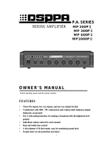
5. Display screen
It is used to display the operation status of the equipment, for example:
① To read the volume scale and numeral of various channels directly from the screen;
② The dynamic display of output signal, and the display of the positions of treble and bass scales;
③ When regulating the parameters, the changes in the parameters are displayed on the screen in a
real-time manner.
6. Master volume control button
The button VOLUME is used to regulate the master output volume. Button ‘+’ is used to increase the volume,
and the button ‘-’ is used to decrease the volume, with the amplitude displayed on the display screen in a
real-time manner:
Display of numeral: The maximum volume is “79”, and the minimum volume is “00”.
Display of scale: In case of increase in volume, the scale cursor moves upward; in case of decrease in
volume, the scale cursor moves downward.
7. Bass control button
Button BASS is used to increase or attenuate the tune of the bass. Button ‘+’ is used to increase the tune of
bass, and the button ‘-’ is used to attenuate the tune of the bass, with the amplitude displayed on the display
screen in a real-time manner:
Display of numeral: The maximum amplitude of bass increase is “+10”, and the maximum amplitude
of bass attenuation is “-10”.
Display of scale: In case of increase in bass tune, the scale cursor moves upward; in case of attenuation
21 43 15
3
2 54
VOL BAS
TRE
79 79 79 79 79 79 79 79 79 79
44
00 00
0
音量刻度显示 音量数字显示
输入电平指示
输出电平指示
高低音调刻度显示
辅助输入音量状况显示 话筒音量状况显示
Display of
volume scale
Display of
volume numeral
Display of
input level
Display of
output level
Display of microphone volume
Display of treble and bass scales
Display of auxiliary input volume

* Fire-fighting/public addressing system Series PC10
5
in bass tune, the scale cursor moves downward.
Attention: If it is not necessary to increase or attenuate the bass tune, please turn the bass tune to the
position of scale “0”.
8. Treble control button
Button TREBLE is used to increase or attenuate the tune of the treble. Button ‘+’ is used to increase the tune
of treble, and the button ‘-’ is used to attenuate the tune of treble, with the amplitude displayed on the display
screen in a real-time manner:
Display of numeral: The maximum amplitude of treble increase is “+10”, and the maximum amplitude
of treble attenuation is “-10”.
Display of scale: In case of increase in treble tune, the scale cursor moves upward; in case of attenuation
in treble tune, the scale cursor moves downward.
Attention: If it is not necessary to increase or attenuate the treble tune, please turn the treble tune to the
position of scale “0”.
9. Bell tune button
Press this button to make a string of prompt bell tunes “1-3-5-ì-” so as to catch the attention of the
audience.
10. MIC1 input port
It is the MIC (microphone) input port with the highest priority, and the signal input through which will
automatically restrain the signals input from other input ports.

* Fire-fighting/public addressing system Series PC10
6
(B) Rear panel
1. Remote-control input port
The remote-control input port connected to the previous equipment.
2. Remote-control output port
The remote-control input port connected to the next equipment.
3. Bell tune control knob
To regulate the output volume of the bell tune by turning clockwise to increase the volume,
and turning counterclockwise to decrease the volume.
4. MIC2, 3, 4, and 5 input ports
The microphone 2 to 5 input ports are connected by use of 6.35mm plug.
The microphone port has three non-equilibrium ports and two equilibrium ports.
The plug of the non-equilibrium port is as shown in the right figure.
5. EMC1 and 2 input ports
Such two ports are used to connect the alarm signal and timely bell tune with the priority only second to that
of the MIC1 port. It is recommended to connect the microphone for emergency broadcasting to “MIC1”, to
connect the sound source for local calls to “EMC1”, and to connect the timely bell tune to “EMC2” by
means of the 6.35mm plug.
6. AUX1, 2 and 3 inputs
Such tree input ports are used to input the peripheral sound source signals, such as CD, cassette deck and
tuner, which are connected by means of the lotus-form plug.
7. Audio output port
Such port is used to connect the amplifier or the tuner equipment, which is connected by means of the
lotus-form plug.
8. 24V DC power input port
It is used as the incoming port of the 24V DC backup power. When connecting, pay attention to the positive
and negative poles.
9. AC power input socket
The AC power cable is inserted into such socket.
10. AUX4 and 5 inputs
As the peripheral sound source input port, it is connected by means of 6.35mm plug.
11. AC 110V/220V selector switch
It is used to select the working voltage.
(Legend of 6.35mm plug)
Obverse Input
Ground
Reverse Input
BALANCED
INPUT
DATA OUT
DATA IN
MIC4
MIN MAX
MIC2 MIC3
CAUTION:
RISK OF ELECTRIC
SHOCK.DO NOT OPEN!
AUX4
CHIME
VOL
INPUT
VOLTAGE SELECTOR
MIC5 EMC1 EMC2
~115V-230V/50Hz-60Hz/10W
AUX2
AUX5
INPUT
AUX1
OUTPUT
AUX3
+24VDC
GND.
STATION
POWER INPUT
+24VDC
GND.
STATION
POWER OUTPUT
FUSE RATING
F1AL: ~110-115V
F0.6AL: ~220-230V
~110-115V/50Hz-60Hz
~220-230V/50Hz-60Hz
115V
230V
请勿打开,以免触电
警告
MODEL:
广州市迪士普音响科技有限公司
Guangzhou DSPPA Audio Co.,Ltd.
公共广播系统控制器
1 2 3
4 5
6 8 9
7
121110

* Fire-fighting/public addressing system Series PC10
7
12. Power fuse block
It is used to fix the AC power fuse. If such fuse is melted, the fuse in the same specification shall be used for
replacement. The continuous melting of the fuse indicates the failure.
(C) Rear panel
C. Operation Instructions
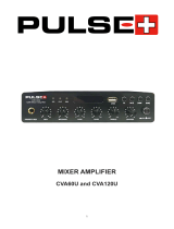
(A) Selection of Power Supply Mode
To meet the requirements of different power supply voltage in different countries, all devices in PC-LINK
system have three types of working voltage:
① AC220-230V working voltage; ② AC110-115V working voltage;③ DC24V working voltage, which
is used as the backup power supply in the system, i.e. in case of AC220V or AC110V is not available,
the device can operate normally under the DC24V power supply. The DC24V power supply is supplied
by PC1022E (emergency power supply device for PA system).
Use voltage selector on the back panel (shown in the following figure) to select working voltage.
Selection of AC110V Selection of AC220V
1) When the selector is turned to the right till “115” appears, the working voltage of the device is set
to AC110V-115V.
2) When the selector is turned to the left till “230” appears, the working voltage of the device is set to
AC220V-230V.
3) DC24V can be used directly if neither of the above two types of power is available.
POWER
CHIME
TREBLE
AUX5
AUX4
AUX3
AUX2
MIC5
AUX1
MIC4
MIC3
MIC1
MIC2
BASS
+
PROFESSIONAL PERIPHERAL DEVICE
TREBLE
+
VOLUME
+
MIC1 MIC2
MIC3
MIC4 MIC5
AUX1 AUX2 AUX3
AUX4 AUX5
+ + + + + + + + + +
+12dB
+8dB
+6dB
+2dB
0dB
-2dB
-6dB
-18dB
-40dB
BASS
VOLUME
Pre Amplifier PC1011PII
Amplifier
PC-series
Tuner
PC-series
Cassette
PC-series
CD
player
PC-series
Emergency
Panel
Timing
Chime
OUTPUT
AUX3
AUX2
AUX1
EMC2
EMC1
MIC2
Priority MIC

* Fire-fighting/public addressing system Series PC10
8
(B) Address setting
There is a set of PC10 system to allow the multiple link of this equipment. In order for distinguishing, it is
necessary to set different addresses for any equipment. The address of the equipment makes use of 4 binary
codes “0” and “1” for setting. By means of the address setting, it is possible to connect 16 PC1011PII
equipments in a set of system in a parallel manner. The setting method is described as follows.
Prior to power-on, press down the button “+” for control of the total volume “VOLUME”, and then turn
on the power until the interface as shown in figure (2) is displayed on the screen, in which the 4 digits refer to
the address of the equipment.
1) When setting the address, the address of the first
equipment in the same type is set to 0000, the
address of the second is set to 0001 and so on. If
there is only one local machine in a set of the
system, its address is set to 0000. Please refer to the
“address table” attached for the corresponding
relationship between the address sequence of the
equipment and the binary values.
2) The “+”keys of the eight volume control buttons
MIC1-MIC4 on the panel are used to adjust the
address digits to “1”, and the “-
” keys are used to
adjust the address digits to “0”.Taking figure (3) as
the example, the two keys of MIC1 are used to
adjust the first digit; the two keys of MIC2 are used
to adjust the second digit, and so on.
3) After completing the setting of the address, press
the key “ - ” of total volume control button
“VOLUME” to confirm and exit the setting
interface.
Figure (3) Example for address setting mode
MIC1 MIC2
MIC3 MIC4
+
+
+
+
Figure (1) buttons for
address setting
Figure (2) interface
for address setting
MIC1 MIC2 MIC3 MIC4
+ + +
+
Set Address
0
1 1
0
0
1
Set Address
1
0

* Fire-fighting/public addressing system Series PC10
9
(C) Remote-control operation
1. This machine is subject to the remote control by PC. By connecting the remote link port to the
remote link port of other equipment with the network table, it is possible to operate and control by
means of the computer installed with the control software of this system. The network cable is the
T568A-T568A network cable as shown in figure (D). Please refer to the operating instructions to the
PC software for the monitoring operation of PC. If PC monitoring is not necessary, do not connect.
If the PC1005U router is connected in the system, first connect the data output port “DATA OUT” of
PC1005U to the data input port “DATA IN” of this equipment first, or connect the output port
“DATA OUT” of PC1005U to the input port “DATA IN” of other equipment, and then connect to this
equipment. Afterwards, connect the other equipments one by one in series. All the network cables are
connected by the method for T-568A ~ T-568A network cable. The connecting method is as shown in
the following figure.
PC1011PII Peripheral equipment Peripheral equipment
2. If there is no PC1005U in the system, the “DATA” port of the machine is used only to transfer the
data signal between the peripheral equipments. Please connect the “DATA” port of the equipment to
the port “DATA” of the other equipment in series. The connecting method is as shown in the
following figure:
Local machine or other
peripheral equipments
Local machine or other
peripheral equipments
Local machine or other
peripheral equipments
Connect remote control
ports of all the machines
in series
Connect remote control
ports of all the machines
in series
PC1005 DATA OUT
port from the router
DATA OUT port
from other
equipment
Connect remote control
ports of all the machines
in series
DATA OUT port
from other
equipment

* Fire-fighting/public addressing system Series PC10
10
D. Packing list
One PC1011PII (Preamplifier) equipment, one operation instruction, one warranty card, one certificate,
one 568A-568A cable, one SY542 audio cable, two (2) audio conversion plugs, one power cable, M5*18
cup-head stainless steel screws, black gaskets, one 24V strand wire with plugs at both ends.
E. After-sale Services
1. We provide the one-year warranty free of charge (including free supply of spare parts) for any quality
problem of the product from the day of purchase, if product is installed and used according to this
manual strictly.
2. The user must provide the warranty card and sales invoice before the warranty is provided.
3. The following conditions are not covered by free warranty:
(1) Damages caused by improper installation, use or handling;
(2) Failure of product due to abnormal conditions (e.g. excessively high supply voltage or ambient
humidity, etc);
(3) Damage to product due to natural and man-made disasters and accidents;
(4) The number of product is changed, altered or deleted;
(5) The product has been repaired or refitted by personnel without the authorization of our
company;
4. Please keep the manual and warranty card properly.
5. For questions or matters not mentioned in the manual, please contact the dealer or visit our website
http://www.dsppa.com for more information.
6. In case of any failure of the device during the warranty period, please contact our staff (or the dealer).
We are not responsible for any free maintenance if the product is damaged due to disassemble by the
users themselves or due to repair by personnel other than our technicians.

* Fire-fighting/public addressing system Series PC10
11
Operation Instructions
Data interface
(link to all devices)
Override signal
AC220V
DC24V
Telephone line
Audio signal line
Data signal line
Alarm signal
PC1010R
Main’s AMP.-1
PC SERIES
PC1020S
PC1010P
PC1015E
MIC
AC 220V
Power supply
PC1024L
SPEAKER OUTPUT
—CH2
PC1013B
PC1012M
PC1021M
SUB’s AMP.
PC SERIES
Main’s AMP.-2
PC SERIES
PC1016E
PC1011PII
PC1014T
SPEAKER OUTPUT
—CH1
PC1022E
PC1023S PC1019A PC1018T
Alarm signal
(from fire center)
AC220V
Telephone
interface
EMC1
EMC2
AUX2
AUX3
AUX4
MIC1
MIC
DC 24V
Power
supply
PC1017PII
PC1008R
PC1007C
PC1006D
AUX1
Chime signal
Remote control
(from PC)
Zone-1 Zone-n
PC1005U
BATTERY
AUDIO IN
—CH1
AUDIO IN
—
CH2
AUDIO OUT TO SUB
’S
AUDIO OUT
TO MAIN’S
MAIN AMP
’S INPUT
Alarm signal
O
ther signal
SUB AMP
’S INPUT
MAI
N AMP’S INPUT
AUDIO OUT TO MAIN
’S
CH B
CH A

* Fire-fighting/public addressing system Series PC10
12
Attachment
Corresponding table for address:
Unit No.
Address
Number
Unit No.
Address
Number
Unit No.
Address
Number
Unit No.
Address
Number
Unit 1 0000 Unit 5 0100 Unit 9 1000 Unit 13 1100
Unit 2 0001 Unit 6 0101 Unit 10 1001 Unit 14 1101
Unit 3 0010 Unit 7 0110 Unit 11 1010 Unit 15 1110
Unit 4 0011 Unit 8 0111 Unit 12 1011 Unit 16 1111
Specifications
Input
Mic1, 2, 3 : 600Ω, 2.5mV, unbalanced
Mic4,5:600Ω,2.5mV, balanced
EMC1, 2 ; Aux1, 2, 3 : 10kΩ, 250mV, unbalanced
Aux4,5 : 10kΩ, 250mV, balanced
Output
0dBV
Frequency response
20Hz-25kHz(
±
3dB)
,
line input
THD
Aux : 0.05%,Mic : 0.3%
Signal/ noise ratio
Mic input : >80dB
Aux input : >85dB
Tone
Bass : ±10dB(100Hz)
Treble : ±10dB(10kHz)
Chime
Press the button once,the tune is “(1-3-5-ì-) ”,
Volume
adjustable.
Protection
AC fuse×1(220V: F0.6AL, 110V: F1AL)
Power Requirement
1. AC110-115V/220-230V 50/60Hz
2. DC24V
Outer Packing Size
(
mm
)
(
L×W×H
)
555×455×185
Unit Size(mm) (L×W×H)484×349.5×88
Gross weight 8.5kg
Net weight 6.7kg
Specifications are subject to change without notice
CAUTION
● When the “Power switch” is off, please pull out the power cord from the socket.
Please keep the equipment out of water.
● To reduce the risk of electric shock, do not remove the cover.
● No user parts inside. Refer servicing to qualified service personnel.
Guangzhou DSPPA Audio Co., Ltd.
/