Page is loading ...

OPERATOR'S
MANUAL
Model C303NP & C314NP
Non-Pressurized Slush Freezer
Original Operating Instructions
066732NP 11/10/09 (Original Publication)
(Updated 7/24/15)

Complete this page for quick reference when service is required:
Taylor Distributor:
Address:
Phone:
Fax:
E-mail:
Service:
Parts:
Date of Installation:
Cycle
A
A
Information found on the data label:
Model Number:
Serial Number:
Electrical Specs: Voltage
Phase
Maximum Fuse Size:
Minimum Wire Ampacity:
E 2009 Taylor Company
066732NP
Any unauthorized reproduction, disclosure, or distribution of copies by any person of any portion of this
work may be aviolation of Copyright Law of the United States of America andother countries, could result
in the awarding of Statutory Damages of up to $250,000 (17 USC 504) for infringement, and may result
in further civil and criminal penalties. All rights reserved.
Taylor Company
750 N. Blackhawk Blvd.
Rockton, IL 61072

Table of Contents Models C303NP & C314NP
Table of Contents
Section 1 To the Installer 1............................................
Section 2 To the Operator 5...........................................
Section 3 Safety 7....................................................
Section 4 Operator Parts Id en t ificatio n 9...............................
Model C303NP 9.......................................................
Model C314NP 10.......................................................
Beater Door Assembly 11.................................................
Accessories 12..........................................................
Section 5 Important: To the Operator 13.................................
Control Switch 14........................................................
Liquid Crystal Display 14..................................................
Operational Mode Displays 14.............................................
Operator Menu Display 15................................................
Syrup Out Indicator 21....................................................
Water Out Indicator 22....................................................
Audio Alarm Silencer 22..................................................
Product Not Ready Light 22...............................................
Sampling Valve 22.......................................................
Section 6 Operating Procedures 23.....................................
Assembly 23............................................................
Sanitizing 28............................................................
Priming/Brixing 30........................................................
Daily Cleaning Procedures 32.............................................
120 Day Closing Procedure 32............................................
Draining Product From the Fr eezing Cylinders 33............................
Rinsing 33..............................................................
Cleaning 34.............................................................

Models C303NP & C314NP Table of Contents
Table of Contents - Page 2
Disassembly 35..........................................................
Brush Cleaning 35.......................................................
Section 7 Important: Operator Checklist 37..............................
During Cleaning and Sanitizing 37.........................................
Troubleshooting Bacterial Count 37........................................
Regular Maintenance Checks 37...........................................
Winter Storage 38........................................................
Section 8 Troubleshooting Guide 39....................................
Section 9 Parts Replacement Schedule 42...............................
Section 10 Limited Warranty on Equipment 43............................
Section 11 Limited Warranty on Parts 45.................................
Note: Continuing research r esults in steady improvements; therefore, information
in this manual is subject
to change without notice.
Note: Only instructions originating from the factory or its authorized translation
representative(s) are considered to be the original set of instructions.
E 2009 Taylor Company (Original Publication)
(Updated July, 2015)
066732NP
Any unauthorized reproduction, disclosure, or distribution of copies by any person of any portion of this
work may be a violation of Copyright Law of the United States of America andother countries, could result
in the awarding of Statutory Damages of up to $250,000 (17 USC 504) for infringement, and may result
in further civil and criminal penalties. All rights reserved.
Taylor Company
750 N. Blackhawk Blvd.
Rockton, IL 61072

1
Models C303NP & C314NP To the Installer
131212
Section 1 To the Installer
The following information has been included in the
manual as safety and regulatory guidelines. For
complete installation instructions, please see the
Installation Checklist.
Installer Safety
In all areas of the world, equipment should
be installed in accordance with existing local codes.
Please contact your local authorities if you have any
questions.
Care should be taken to ensure that all basic safety
practices are followed during the installation and
servicing activities related to the installation and
service of Taylor equipment.
S Only authorized Taylor service personnel
should perform installation and repairs on
the equipment.
S Authorized service personnel should consult
OSHA Standard 29CFRI910.147 or the
applicable code of the local area for the
industry standards on lockout/tagout
procedures before beginning any installation
or repairs.
S Authorized service personnel must ensure
that the proper PPE is available and worn
when required during installation and
service.
S Authorized service personnel must remove
all metal jewelry, rings, and watches before
working on electrical equipment.
The main power supply(s) to the equipment
must be disconnected prior to performing any
repairs. Failure to follow this instruction may result in
personal injury or death from electrical shock or
hazardous moving parts as well as poor
performance or damage to the equipment.
Note:Allrepairsmustbeperformedbyan
authorized Taylor Service Technician.
This unit has many sharp edges that can
cause severe injuries.
Site Preparation
Review the area where the unit will be installed
before uncrating the unit. Make sure that all possible
hazards to the user and the equipment have been
addressed.
For Indoor Use Only: This unit is designed to
operate indoors, under normal ambient
temperatures of 70_-75_F(21_-24_C). The freezer
has successfully performed in high ambient
temperatures of 104_(40_C) at reduced capacities.
This unit must NOT beinstalledinanarea
where a water jet or hose can be used. NEVER use
a water jet or hose to rinse or clean the unit. Failure
to follow this instruction may result in electrocution.
This unit must be installed on a level surface
to avoid the hazard of tipping. Extreme care should
be taken in moving this equipment for any reason.
Two or more persons are required to safely move
this unit. Failure to comply may result in personal
injury or equipment damage.
Uncrate the unit and inspect it for damage. Report
any damage to your Taylor Distributor.
This piece of equipment is made in the USA and has
USA sizes of hardware. All metric conversions are
approximate and vary in size.
Air Cooled Units
DO NOT obstruct air intake and discharge openings:
Air cooled units require a minimum of 3” (76 mm) of
air space both sides, 3” (76 mm) at the rear, and 12”
(305 mm) on the top of the unit. Minimum air
clearances must be met to assure adequate air flow
for optimum performance.

2
Models C303NP & C314NPTo the Installer
150724
Water Cooled Refrigeration Units
(Water Cooled Units Only)
On the back of the unit, two additional 3/8” (9.5 mm)
F.P.T. water connections for condenser inlet and
outlet have been provided for easy hook-up. 3/8”
(9.5 mm) inside diameter water lines should be
connected to the machine. Flexible lines are
recommended if local codes permit. Failure to use
adequate size water lines may cause the unit to go
on high head pressure and shut down.
Depending on local water conditions, it may be
advisable to install a water strainer to prevent
foreign substances from clogging the automatic
water valve.
DO NOT INSTALL A HAND SHUT-OFF VALVE ON
THE “OUT” LINE! Water cooled units are counter
flow and the water should flow in this order: First
through the automatic water valve. Second, through
the inlet located at the bottom of the condenser.
Third, through the outlet fitting located at the top of
the condenser toanopentrapdrain.
IMPORTANT: Water pressures are pre-set at the
factory. Do not adjust the water pressure.
Improper water adjustments may cause operation
discrepancies.
Water Connections
An adequate cold water supply must be provided
with a hand shut-off valve. On the back of the unit, a
3/8” (9.5 mm) male flare water connection has been
provided for easy hook-up. A flexible line is
recommended, if local codes permit. A minimum of
25 psi (172 kPa) water pressure is required to avoid
having the unit cut out the low water pressure
switch. A booster pump must be provided if this
pressure is not available.
Note: Water lines beyond 200 ft. (61 m) require 1/2”
(13 mm) water lines.
INSTALL POTABLE WATER CONNECTION
WITH ADEQUATE BACK-FLOW
PROTECTION TO COMPLY WITH
APPLICABLE NATIONAL, STATE, AND
LOCAL CODES.
It is always a good practice to have a filter system to
improve the quality of the water and to avoid
clogging the operating components.
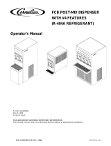
IMPORTANT: The water filter (064422-SER) must
be thoroughly flushed with water before connecting it
to the machine. This removes any loose particles
present from the manufacture of the filter that could
clog the flow control. To flush the filter, connect the
inlet end of the filter to the water supply. Position the
outlet end of the filter over an empty pail. Open the
water supply. Allow water to flow through the filter
until the water exiting the filter is clear. Close the
water supply. Attach the outlet end of the filter to the
machine. Reopen the water supply.
Figure 1

3
Models C303NP & C314NP To the Installer
131212
Electrical Connections
Each unit requires one power supply for each data
label on the unit. Check the data label(s) on the
freezer for branch circuit overcurrent protection or
fuse, circuit ampacity, and other electrical
specifications. Refer to the wiring diagram provided
inside the electrical box for proper power
connections.
In the United States, this equipment is intended to
be installed in accordance with the National
Electrical Code (NEC), ANSI/NFPA 70-1987. In all
other areas of the world, equipment should be
installed in accordance with the existing local codes.
Please contact your local authorities.
The purpose of the NEC code is the practical
safeguarding of persons and property from hazards
arising from the use of electricity. This code contains
provisions considered necessary for safety.
Compliance therewith and proper maintenance will
result in an installation essentially free from hazard!
The NEC is a United States regulatory agency.
International users must follow local electrical codes.
FOLLOW YOUR LOCAL ELECTRICAL CODES!
CAUTION: THIS EQUIPMENT MUST BE
PROPERLY GROUNDED! FAILURE TO DO SO
CAN RESULT IN SEVERE PERSONAL INJURY
FROM ELECTRICAL SHOCK!
This unit is provided with an equipotential
grounding lug that is to be properly attached to the
rear of the frame by the authorized installer. The
installation location is marked by the equipotential
bonding symbol (5021 of IEC 60417-1) on both the
removable panel and the equipment's frame.
S Stationary appliances which are not
equipped with a power cord and a plug or
another device to disconnect the appliance
from the power source must have an all-pole
disconnecting device with a contact gap of
at least 3 mm installed in the external
installation.
S Appliances that are permanently connected
to fixed wiring and for which leakage
currents may exceed 10 mA, particularly
when disconnected or not used for long
periods or during initial installation, shall
have protective devices such as a GFI, to
protect against the leakage of current,
installed by the authorized personnel to the
local codes.
S Supply cords used with this unit shall be
oil-resistant, sheathed flexible cable not
lighter than ordinary polychloroprene or
other equivalent synthetic
elastomer-sheathed cord (Code designation
60245 IEC 57) installed with the proper cord
anchorage to relieve conductors from strain,
including twisting, at the terminals and
protect the insulation of the conductors from
abrasion.
If the supply cord is damaged, it must be
replaced by an authorized Taylor service
technician in order to avoid a hazard.
CAUTION: THIS EQUIPMENT MUST BE
PROPERLY GROUNDED! FAILURE TO DO SO
CAN RESULT IN SEVERE PERSONAL INJURY
FROM ELECTRICAL SHOCK!

4
Models C303NP & C314NPTo the Installer
131212
Beater Rotation
Beater rotation must be clockwise as viewed
looking into the freezing cylinder.
If rotation is not correct, the individual beater motor
wiring should be checked by an authorized Taylor
service technician.
Initial Freezing Cylinder Cleaning
Due to the types of products used in FCB
equipment, it is imperative that the freezing cylinder
and the inlet tube be thoroughly brush cleaned,
rinsed, and sanitized before running any product.
Prepare a cleaning solution, using 2 oz. of liquid
detergent in 2 gallons of warm water. Using this
solution, brush clean the freezing cylinder and the
inlet tube. Rinse the freezing cylinder and the inlet
tube with clean water. Sanitize, using the sanitizing
procedures outlined in this Operator Manual, starting
on page 28.
Refrigerant
In consideration of our environment, Taylor
uses only HFC refrigerants. The HFC refrigerant
used in this unit is R404A. This refrigerant is
generally considered non-toxic and non-flammable,
with an Ozone Depleting Potential (ODP) of zero (0).
However, any gas under pressure is potentially
hazardous and must be handled with caution.
NEVER fill any refrigerant cylinder completely with
liquid. Filling the cylinder to approximately 80% will
allow for normal expansion.
Use only R404A refrigerant that conforms
to the AHRI standard 700 specification. The use of
any other refrigerant may expose users and
operators to unexpected safety hazards.
Refrigerant liquid sprayed onto the skin may
cause serious damage to tissue. Keep eyes and skin
protected. If refrigerant burns should occur, flush
immediately with cold water. If burns are severe,
apply ice packs and contact a physician
immediately.
Taylor reminds technicians to be aware of
and in compliance with local government laws
regarding refrigerant recovery, recycling, and
reclaiming systems. For information regarding
applicable local laws, please contact your local
authorized Taylor distributor.
WARNING: R404A refrigerant used in
conjunction with polyolester oils is extremely
moisture absorbent. When opening a refrigeration
system, the maximum time the system is open must
not exceed 15 minutes. Cap all open tubing to
prevent humid air or water from being absorbed by
the oil.

5
Models C303NP & C314NP To the Operator
131212
Section 2 To the Operator
The unit you have purchased has been carefully
engineered and manufactured to give you
dependable operation.
This unit, when properly operated and cared for, will
produce a consistent quality product. Like all
mechanical products, it will require cleaning and
maintenance. A minimum amount of care and
attention is necessary if the operating procedures
outlined in this manual are followed closely.
This Operator's Manual should be read
before operating or performing any maintenance on
the unit.
Your Taylor unit will NOT compensate for and/or
correct any errors made during the set-up or filling
operations. Thus, the initial assembly, set-up, and
priming procedures are of extreme importance. It is
strongly recommended that all personnel
responsible for the unit's operation, including
assembly and disassembly, go through these
procedures together in order to be properly trained
and to make sure that all understand their role in
using and maintaining the unit.
In the event you should require technical assistance,
please contact your local authorized Taylor
Distributor.
Note: Your Taylor warranty is valid only if the parts
are authorized Taylor parts, purchased from the
local authorized Taylor Distributor, and only if all
required service work is provided by an authorized
Taylor service technician. Taylor reserves the right
to deny warranty claims on units or parts if
non-Taylor approved parts or incorrect refrigerant
were installed in the unit, system modifications were
performed beyond factory recommendations, or it is
determined that the failure was caused by abuse,
misuse, neglect, or failure to follow all operating
instructions. For full details of your Taylor Warranty,
please see the Limited Warranty section in this
manual.
Note: Constant research results in steady
improvements; therefore, information in this
manual is subject to change without notice.
If the crossed out wheeled bin symbol is
affixed to this product, it signifies that this product is
compliant with the EU Directive as well as other
similar legislation in effect after August 13, 2005.
Therefore, it must be collected separately after its
use is completed, and cannot be disposed as
unsorted municipal waste.
The user is responsible for returning the product to
the appropriate collection facility, as specified by
their local code.
For additional information regarding applicable local
laws, please contact the municipal facility and/or
local distributor.

6
Models C303NP & C314NPTo the Operator
131212
Compressor Warranty Disclaimer
The refrigeration compressor(s) on this unit are
warranted for the term stated in the Limited
Warranty section in this manual. However, due to
the Montreal Protocol and the U.S. Clean Air Act
Amendments of 1990, many new refrigerants are
being tested and developed, thus seeking their way
into the service industry. Some of these new
refrigerants are being advertised as drop-in
replacements for numerous applications. It should
be noted that in the event of ordinary service to this
unit's refrigeration system, only the refrigerant
specified on the affixed data label should be
used. The unauthorized use of alternate refrigerants
will void your Taylor compressor warranty. It is the
unit owner's responsibility to make this fact known to
any technician he employs.
It should also be noted that Taylor does not warrant
the refrigerant used in its equipment. For example, if
the refrigerant is lost during the course of ordinary
service to this unit, Taylor has no obligation to either
supply or provide replacement refrigerant either at
billable or unbillable terms. Taylor will recommend a
suitable replacement if the original refrigerant is
banned, obsoleted, or no longer available during the
five (5) year Taylor warranty of the compressor.
From time-to-time Taylor may test new refrigerant
alternates. Should a new refrigerant alternate prove,
through Taylor's testing, that it would be accepted as
a drop-in replacement for this unit, then the
disclaimer in this “Compressor Warranty Disclaimer”
section will not apply to the use of the alternate
refrigerant approved by Taylor.
To find out the current status of an alternate
refrigerant as it relates to your compressor warranty,
call Taylor or your local authorized Taylor distributor.
Be prepared to provide the Model/Serial Number of
the unit in question.
Note: Continuing research results in steady
improvements; therefore, information in this
Operator Manual is subject to change without
notice.

7
Models C303NP & C314NP Safety
Section 3 Safety
We, at Taylor Company, are concerned about the
safety of the operator at all times when they are
coming in contact with the unit and its parts. Taylor
makes every effort to design and manufacture
built-in safety features to protect both operators and
service technicians.
Installing and servicing refrigeration equipment can
be hazardous due to system pressure and electrical
components. Only trained and qualified service
personnel should install, repair, or service
refrigeration equipment. When working on
refrigeration equipment, observe precautions noted
in the literature, tags and labels attached to the unit,
and other safety precautions that may apply. Follow
all safety code requirements. Wear safety glasses
and work gloves.
IMPORTANT - Failure to adh ere to the
following safety precautions may result in
severe personal injury or death. Failure to
comply with these warnings may also damage
the unit and/or its components. Such damage
may result in component replacement and
service repair expenses.
DO NOT operate the unit without reading
this entire Operator Manual first. Failure to follow all
of these operating instructions may result in damage
to the unit, poor performance, health hazards,
personal injury, or death.
This unit is to be used only by trained
personnel. It is not intended for use by children or
people with reduced physical, sensory, or mental
capabilities, or lack of experience and knowledge.
Where limited equipment operation is allowed for
public use, such as a self-serve application,
supervision or instruction concerning the use of the
appliance by a person responsible for their safety is
required. Children should be supervised to ensure
that they do not play with the appliance.
S All repairs should be performed by an
authorized Taylor service technician.
S The main power supplies to the unit must be
disconnected prior to performing installation,
repairs, or maintenance.
S DO NOT operate the unit unless it is
properly grounded.
S DO NOT operate the unit with larger fuses
than specified on the unit's data label.
S Cord Connected Units: Only Taylor
authorized service technicians or licensed
electricians may install a plug or
replacement cord on these units.
S Units that are permanently connected to
fixed wiring and for which leakage currents
may exceed 10 mA, particularly when
disconnected or not used for long periods,
or during initial installation, shall have
protective devices such as a GFI, to protect
against the leakage of current, installed by
the authorized personnel to the local codes.
S Stationary units which are not equipped with
a power cord and a plug or another device
to disconnect the appliance from the power
source must have an all-pole disconnecting
device with a contact gap of at least 3 mm
installed in the external installation.
S Supply cords used with this unit shall be
oil-resistant, sheathed flexible cable not
lighter than ordinary polychloroprene or
other equivalent synthetic
elastomer-sheathed cord (Code designation
60245 IEC 57) installed with the proper cord
anchorage to relieve conductors from strain,
including twisting, at the terminals and
protect the insulation of the conductors from
abrasion.
If the supply cord is damaged, it must be
replaced by an authorized Taylor service
technician in order to avoid a hazard.
Failure to follow these instructions may result in
electrocution. Contact your local authorized Taylor
Distributor for service.

8
Models C303NP & C314NPSafety
131212
DO NOT use a water jet to clean or rinse
the unit. Failure to follow these instructions may
result in serious electrical shock.
S DO NOT allow untrained personnel to
operate this unit.
S DO NOT operate the unit unless all service
panels and access doors are restrained with
screws.
S DO NOT remove any internal operating
parts (including, but not limited to, freezer
door, beater, or scraper blades), unless all
control switches are in the OFF position.
Failure to follow these instructions may result in
severe personal injury, especially to fingers or
hands, from hazardous moving parts.
This unit has many sharp edges that can
cause severe injuries.
S DO NOT put objects or fingers in the door
spout. This may contaminate the product
and cause severe personal injury from blade
contact.
S USE EXTREME CAUTION when removing
the beater assembly. The scraper blades
are very sharp.
This unit must be placed on a level surface.
Extreme care should be taken when moving the unit
for any reason. Two or more persons are required to
safely move this unit. Failure to comply may result in
personal injury or damage to the unit.
Access to the service area of the unit must
be restricted to persons having knowledge and
practical experience with the unit, in particular as far
as safety and hygiene are concerned.
Cleaning and sanitizing schedules are
governed by your state or local regulatory agencies
and must be followed accordingly. Please refer to
the cleaning section of this Operator Manual for the
proper procedure to clean this unit.
This unit is designed to maintain product
temperature under 41°F (5°C). Any product being
added to this unit must be below 41°F (5°C). Failure
to follow this instruction may result in health hazards
and poor freezer performance.
DO NOT run the unit without product. Failure to
follow this instruction can result in damage to the
unit.
DO NOT obstruct air intake and discharge openings:
Air cooled units require a minimum of 3” (76 mm) of
air space on both sides, 3” (76 mm) at the rear, and
12” (305 mm) on the top of the unit. Minimum air
clearances must be met to assure adequate air flow
for optimum performance.
Failure to allow adequate clearance can reduce the
refrigeration capacity of the unit and possibly cause
permanent damage to the compressor.
For Indoor Use Only: This unit is designed to
operate indoors, under normal ambient
temperatures of 70°-75°F (21°-24°C). The unit has
successfully performed in high ambient
temperatures of up to 104°F (40°C) at reduced
capacities.
NOISE LEVEL: Airborne noise emission does not
exceed 78 dB(A) when measured at a distance of
1.0 meter from the surface of the unit and at a
height of 1.6 meters from the floor.

9
Models C303NP & C314NP Operator Parts Identification
150421
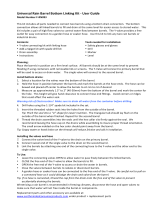
Section 4 Operator Parts Identification
Model C303NP
Figure 2
ITEM DESCRIPTION PART NO.
1 PANEL-SIDE-LEFT 059721
2 PANEL A.-REAR AC X66671
3 PANEL-SIDE-RIGHT 059722
4 DISPLAY-LED *C303* 15.4" 066670
5 PANEL-FRONT-UPPER 066682
ITEM DESCRIPTION PART NO.
6 PANEL-FRONT-SHELL 066647
7 PANEL-FRONT-LOWER 066678
8 SHELF - DRIP TRAY 066677
9 TRAY-DRIP 066676
10 SHIELD-SPLASH 066680

10
Models C303NP & C314NPOperator Parts Identification
150421
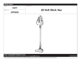
Model C314NP
Figure 3
ITEM DESCRIPTION PART NO.
1 DISPLAY-LED-15.4"TALL 068575
2 PANEL-SIDE-LEFT 059721
3 PANEL A.-REAR X68182
4 SCREW-10-32X1/2 SLTD 037734
5 PANEL-FRONT-UPPER 068496
6 PANEL-FRONT-SHELL 059576-SPN
ITEM DESCRIPTION PART NO.
7 PANEL-FRONT-LOWER 059652
8 PANEL-SIDE-RIGHT 059722
9 SHELF-DRIP-TRAY 059653
10 TRAY-DRIP 059654
11 SHIELD-SPLASH 059659

11
Models C303NP & C314NP Operator Parts Identification
150421
Beater Door Assembly
Figure 4
ITEM DESCRIPTION PART NO.
1 DOOR A.-SLUSH-PARTIAL-SLF X83427SSP
1a DOOR A.-SLUSH-PARTIAL-SLF X83427-SER
1b PIN A.-VALVE HANDLE X83812
1c VALVE-DRAW SELF CLOSE 080662
2 SPRING-COMP.970X.082X3.87 030344
3 O-RING-1"OD X .139W 032504
4 PLUG-PRIME 050405
5 O-RING-.563OD X .070W-#013 043758
6 ARM-BAFFLE 047729
7 BAFFLE A. X47731
8 BEARING-GUIDE 014496
ITEM DESCRIPTION PART NO.
9 O-RING-.291"ID X .080"W 018550
10 BUSTER-ICE 047735
11 SEAL-DRIVE SHAFT 032560
12 NUT-STUD 043666
13 SHAFT-BEATER-SLUSH-NP 067533
14 BEATER A.-7QT-1 PIN X46233
15 BLADE-SCRAPER-PLASTIC 046237
16 CLIP-SCRAPER BLADE 8.75" 046238
17 BEARING-FRONT 013116
18 GASKET-DOOR 5.109 X 5.630 014030
19 HANDLE A.-DRAW X47384

12
Models C303NP & C314NPOperator Parts Identification
150127
Accessories
Figure 5
ITEM DESCRIPTION PART NO.
1 PAIL-10 QT 013163
2 BRUSH A.-PACKAGE X64275
2a BRUSH-MIX PUMP BODY-3”X7” 023316
2b BRUSH-DOUBLE ENDED 013072
2c BRUSH-REAR BRG 1”DX2“L 013071
ITEM DESCRIPTION PART NO.
2d BRUSH-DRAW VALVE 1-1/2”OD 014753
3 KIT A.-TUNE UP X56829
4 LUBRICANT-TAYLOR HI PERF 048232
5 SANITIZER-STERA SHEEN SEE NOTE
*Note: A sample container of sanitizer is sent with the
unit. For reorders, order Stera Sheen part no. 055492
(100 2 oz. packs) or Kay-5 part no. 041082 (200 packs).

13
Models C303NP & C314NP Important: To the Operator
Section 5 Important: To the Operator
Model C303NP Model C314NP
Figure 6
ITEM DESCRIPTION
1 DISPLAY-LIGHTED
2 CONTROL-POWER SWITCH
3 LIQUID CRYSTAL DISPLAY
4 KEY PAD (BARREL #1)
4a OFF KEY
4b AUTO KEY
4c PRIME KEY
4d BEATER KEY
4e ALARM SILENCER KEY
5 KEY PAD (BARREL #2)
5a MENU SELECT KEY
6 KEY PAD (BARREL #3)
7 PRODUCT LIGHT
8 KEY PAD (BARREL #4)
Note: To identify the freezing cylinders on the
C303NP and C314NP, they are counted from left to
right as follows: barrel 1, barrel 2, barrel 3, and
barrel 4. (Note: Barrel 4 is C314NP only.)

14
Models C303NP & C314NPImportant: To the Operator
Control Switch
There is control switch located at the top left corner
of the upper front panel, behind the illuminated
display. When placed in the ON position, this control
switch allows Slushtech operation.
Liquid Crystal Display
There are three Liquid Crystal Displays (LCD)
located on the upper front panel behind the
illuminated display. Each LCD displays information
for the freezing cylinder located directly beneath it.
The LCD shows the current operating mode of the
freezing cylinders. It also indicates whether there is
enough syrup, CO2, and water being supplied to the
freezer. If an error in the machine operation occurs,
a warning tone will sound and the word “FAULT” will
flash on the third line of the display.
Operational Mode Displays
The screens illustrated in this section are those
seen on the Model C303.
(The Model C314 screens vary slightly to include
the fourth barrel information.)
The screens below illustrate the operational mode
information displayed during normal operation. The
LCD displays information corresponding to the three
freezing cylinders located directly beneath them.
When the unit is plugged into the wall receptacle
and the control switch is in the ON position, the
following screen appears. This screen will remain on
the LCD for 60 seconds unless a key is pressed.
SAFETY TIMEOUT
ANY KEY ABORT
If any key is pressed (or 60 seconds elapse) the
following screen appears.
OFF OFF OFF
OK OK OK
CO2-OK WATER-OK
Note: Syrup, CO
2
and water are satisfied.
Pressing the AUTO (- ->) key for each freezing
cylinder will display the following screen.
AUTO AUTO AUTO
OK OK OK
CO2-OK WATER-OK
Line 1 indicates the operating mode for each
freezing cylinder.
Line 2 indicates the status of the syrup system in
each freezing cylinder. As long as syrup is available,
the word “OK” will appear on the LCD. When the
syrup supply is insufficient, the word “OUT” will flash
on the LCD. The same rules apply to the fourth line
which indicates the status of the CO
2
and the H
2
O.
The third line of this display is a fault indicator. If an
error in machine operation occurs, the word “FAULT
will be displayed on the LCD.
BEATER BEATER BEATER
OUT OUT OUT
- -FAULT- -
CO2-OUT H2O-OUT

15
Models C303NP & C314NP Important: To the Operator
Operator Menu Display
The OPERATOR MENU is used to enter the
operating screens. To access the Operator Menu,
press the MENU/SELECT key. The cursor will flash
under the letter “A”, indicating that this is screen A.
To select a different screen, use the AUTO (- ->)
and OFF (<- -) keys to move the cursor to the
desired screen selection and press the
MENU/SELECT key.
OPERATOR MENU
A
BCDEFGHI
EXIT MENU
<- - - -> SEL
Operator Menu Options
A - Exit From Menu
B - Fault Description
C - Set Clock
D - Manual Defrost
E - System Information
F - Current Conditions
G - Fault History
H - Rinse / Sanitize
I - Service Menu
Operator Menu Timeout
If the display is left in the Operator Menu or in any of
the Operator Menu selections except “Current
Conditions”, the display will return to the system
mode screen 60 seconds after the last keypress.
The Current Conditions screen will be displayed until
manually changed.
Fault Description (Opt io n B)
Screen B is FAULT DESCRIPTION. The Fault
Description screen will indicate if there is a fault in
one of the freezing cylinders. Upon correction of the
fault, the warning tone will stop. (Note: “BRL NOT
COOLING” is the only fault that requires pressing
the OFF (<- -) key to clear the fault message and
the warning tone.
Fault Messages
Beater Overload Beater is out on overload.
Chk Refrig Sys Psi Out on compressor high
pressure cut-out.
Thermistor Short Shorted thermistor probe.
Thermistor Open Open thermistor probe.
H2O Pressure Low Water pressure is low.
CO2 Pressure Low CO
2
pressure is low.
Syrup Pressure Low Syrup is no longer present.
BRLTemp2High Freezing cylinder
temperature is above 120_F
(49_C).
BRL Not Cooling Freezing cylinder is not
cooling after 5 minutes.
No Fault Found No fault conditions are
apparent.
The following are explanations of possible faults and
display screens. Pressing the +++ key shows the
faults for each freezing cylinder. The freezing
cylinders are referred to as barrels. They are
counted from left to right as follows: barrel 1, barrel
2, barrel 3, and barrel 4. (Note: Barrel 4 is C314NP
only.)
1. NO FAULT FOUND - No fault conditions are
apparent.
FAULT DESCRIPTION
BARREL 1
NO FAULT FOUND
CLR +++ SEL
2. BEATER OVERLOAD - The beater motor is
out on overload. When this fault occurs, the
affected barrel automatically turns off. The fault
clears when the condition is corrected.
FAULT DESCRIPTION
BARREL 1
BEATER OVERLOAD
CLR +++ SEL

16
Models C303NP & C314NPImportant: To the Operator
3. CHK REFRIG SYS PSI - The compressor is
out on high head pressure. When this fault
occurs, the machine automatically turns off.
The fault clears when the condition is corrected.
FAULT DESCRIPTION
BARREL 1
CHK REFRIG SYS PSI
CLR +++ SEL
4. THERMISTOR SHORT - One of the freezing
cylinder thermistor probes is faulty.
FAULT DESCRIPTION
BARREL 1
THERMISTOR SHORT
CLR +++ SEL
5. THERMISTOR OPEN - One of the freezing
cylinder thermistor probes is faulty.
FAULT DESCRIPTION
BARREL 1
THERMISTOR OPEN
CLR +++ SEL
6. SYRUP PRESS LOW - When the syrup out
indicator displays a lack of syrup, the freezing
cylinder enters the HOLD mode. No
refrigeration or product flow from the flow
control is allowed. The beater will continue to
operate as long as the barrel temperature is
below 50_F(10_C).
FAULT DESCRIPTION
BARREL 1
SYRUP PRESS LOW
CLR +++ SEL
When the syrup is satisfied, the barrel will refill
the product tank and automatically return to the
AUTO mode. The fault message and warning
tone will clear. (See “Syrup Out Indicator” on
page 21.)
7. H
2
O PRESSURE LOW - When the water out
indicator displays a lack of water, a 60 second
internal timer will start. If the water is not
replenished at the end of 60 seconds, all
freezing cylinders will shut down and the
following fault message will appear. When the
water is replenished, the fault message and
warning tone will clear.
FAULT DESCRIPTION
BARREL 1
H2O PRESSURE LOW
CLR +++ SEL
8. BRL NOT COOLING - A freezing cylinder
check has been established for the AUTO
mode of operation. When a freezing cylinder
enters the AUTO mode, the control checks the
product temperature. After five minutes, it
checks the product temperature again. If the
product temperature did not drop in that five
minute time span, the freezing cylinder will shut
down and the following message will appear on
the fault screen. For this check to be valid, the
product temperature must be above 40_F
(4.4_C).
FAULT DESCRIPTION
BARREL 1
BARREL NOT COOLING
CLR +++ SEL
9. BRL TEMP 2 HIGH - A maximum allowable
product temperature has been established to
prevent the product from excessive heating. If
the product exceeds 120_F(49_C) temperature
for any reason (in any mode of operation), the
affected barrel shuts down.
FAULT DESCRIPTION
BARREL 1
BARREL TEMP 2 HIGH
CLR +++ SEL
When faults are corrected, they are cleared from the
fault description screen, with the exception of the
“BRL NOT COOLING” fault. To clear the “BRL NOT
COOLING” fault, press the OFF (<- -) key on the
FAULT DESCRIPTION screen.
To see if there is more than one fault in the freezing
cylinders, press the PRIME (+ + +) key. To return to
the Operator Menu, press the MENU/SELECT key.
To return to the Main Screen, use the AUTO (- ->)
key to cycle t o MENU ITEM A and then press the
MENU/SELECT key.
/