Page is loading ...

IMPORTANT:
Go to www.extron.com for the complete
user guide, installation instructions, and
specifications before connecting the
product to the power source.
MTP/HDMI U R • Setup Guide
The Extron
®
MTP/HDMI U R is a twisted pair and HDMI universal receiver for analog and
DIGITAL OUTPUT
DIGITAL INPUT
POWER
12V
0.8A MAX
12
HDMI
RS-232
PASS THRU
Tx Rx
RGB
VID
Y/C
B-Y
Y
R-Y
ANALOG OUTPUTS
RS-232
Tx Rx
SPARE
MTP INPUT
1
MONO AUDIO
2
MTP/HDMI U R
RGB
PEAKINGLEVEL DIGITAL SIGNAL
ANALOG
SIGNAL
AUDIO
RS-232
VID
Y/C
YUV
RGB
digital signals, and is compatible with MTP and HDMI 201 Tx transmitters.
For full details, see the MTP/HDMI U R User Guide at www.extron.com.
Installation
Step 1 — Mounting
Turn off or disconnect all equipment power sources and mount the device as required.
Step 2 — Connect Input
Connect up to two twisted pair cables from an HDMI 201 Tx to the RJ-45 connectors labeled Digital Inputs 1 and 2. Connect an MTP transmitter,
a switcher, or a Distribution Amplier (DA) to the MTP input.
ATTENTION: Do not connect the twisted pair input cables to a LAN port, or connect a LAN cable to the digital or MTP ports.
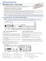
Step 3 — Connect Outputs and RS-232 Control Devices
• Analog video— Connect output devices to the
RGB
VID
Y/C
B-Y
Y
R-Y
ANALOG OUTPUTS
RS-232
Tx Rx
SPARE
1
MONO AUDIO
2
Component Video –
Connect to these 3 BNCs.
Composite Video –
Connect to this BNC.
RGBHV and RGBS –
Connect to this VGA
connector.
S-video – Connect to
this mini DIN connector.
Mono Audio – Connect
to this captive screw
connector.
Wire the RS-232 connector as shown below.
L
MONO AUDIO
R
L
MONO AUDIO
R
Unbalanced Output
Balanced Output
Mono output 1-
Sleeve(s)
Mono output 1+
Mono output 2+
Mono output 2-
Sleeve(s)
Mono output 1
Mono output 2
NO GROUND.
NO GROUND.
Ground
Tx
Rx
Gnd
Receive
Transmit
Connected RS-232 Device Pins
MTP/HDMI U R
Pins
Spare
Spare
Wire the audio connector as shown above.
RS-232 Control (Analog Side) –
Connect to this captive screw
connector.
Do not tin
the wires!
Analog Output connectors (see image to the right).
NOTE: The analog outputs are the signals generated
on the MTP input. The signal is sent to the
appropriate detected analog output.
• Audio — Connect a suitable audio device to the 5-pole
captive screw audio output connector for a balanced or
unbalanced, dual mono audio signal. Wire connector as
shown in the gure at right.
NOTE: The audio signal is detected from the MTP input,
and then is distributed to the audio connector for
output. Audio from the digital side is not available.
• Control device (analog side) — Connect a serial communications port to the upper 3.5 mm, 5-pole captive screw
connector for bidirectional or unidirectional RS-232 communication. Wire the connector as shown in the gure above
NOTE: The RS-232 port configuration (analog side) as unidirectional or bidirectional is controlled by the internal
jumper settings (see Setting the Jumpers on the next page).
• Digital video — Connect a suitable output to the female HDMI output.
Control device (digital side) — Connect a serial communications port to the 3.5 mm, 3-pole
captive screw connector for pass-through RS-232 bidirectional communication. Wire the
connector as shown on the right. .
Step 4 — Connect Power
Wire a standard IEC power cord from a 100 to 240 VAC, 50 - 60 Hz power source into the 12 VDC,
0.8 A, 2-pole captive screw connector (see image a on the right). When power is applied the
front panel power LED lights.
Grounding guidelines
Extron MTP/HDMI U R products can be adversely affected by electrostatic discharge (ESD) if
they are not grounded correctly.
To prevent malfunctions or product damage, an experienced installer can correctly ground an
Extron MTP/HDMI U R in either of two ways:
• Ground the power input port — Insert one end of the grounding wire to the negative or ground
pin on the power input connector (see image a on the right). Tie the other end of the wire to an
earth ground.
• Ground the chassis — Use a connector hex nut as shown in image b the right. Tie the other
end of the wire to an earth ground.
If you have any questions about how to ground a product in a specic application, contact an Extron
technical support specialist.
Connected RS-232
Device Pins
MTP/HDMI
RS-232
Pass-thru
Tx Rx
Rx Tx Grnd
a
Power Supply
Output Cord
SECTION A–A
Ridges
Smooth
AA
POWER
12V
xA MAX
Tie
Wrap
Rear
Panel
Ridges
Earth
Ground
3/16"
(5 mm)
Max.
b

68-1727-50 Rev. D
01 13
MTP/HDMI U R • Setup Guide
Extron Headquarters
+800.633.9876 Inside USA/Canada Only
Extron USA - West Extron USA - East
+1.714.491.1500 +1.919.850.1000
+1.714.491.1517 FAX +1.919.850.1001
FAX
Extron Europe
+800.3987.6673
Inside Europe Only
+31.33.453.4040
+31.33.453.4050 FAX
Extron Asia
+800.7339.8766
Inside Asia Only
+65.6383.4400
+65.6383.4664 FAX
Extron Japan
+81.3.3511.7655
+81.3.3511.7656 FAX
Extron China
+4000.EXTRON
+4000.398766
Inside China Only
+86.21.3760.1568
+86.21.3760.1566
FAX
Extron Middle East
+971.4.299.1800
+971.4.299.1880 FAX
Extron Korea
+82.2.3444.1571
+82.2.3444.1575 FAX
Extron India
1800.3070.3777
Inside India Only
+91-80-3055.3777
+91 80 3055 3737
FAX
© 2013 Extron Electronics All rights reserved. www.extron.com
Input Signal Detection and Front Panel LEDs
ANALOG
SIGNAL
AUDIO
RS-232
VID
Y/C
YUV
RGB
The unit has the ability to output analog and digital signals simultaneously. Check that the displayed output is correct.
The MTP/HDMI U R detects the input signal format, and the appropriate front panel LED (VID, Y/C, YUV, RGB) lights.
When a digital (HDMI) signal is detected, the output is made on the digital HDMI output connector and the Digital Signal
LED lights.
The audio LED is always on, unless an RS-232 signal is detected on the MTP input. The unit differentiates between audio and RS-232 on the MTP
input and routes the signal to the appropriate connector.
Adjusting Peaking and Level
Image sharpness is adjusted with the Peaking control. This applies only to the analog side of the device. Increased peaking compensates for
mid- and high-frequency detail loss. Minimum setting (full counterclockwise) is zero peaking.
Image brightness is adjusted using the Level control.
PEAKING
LEVEL
RGB
For the best image quality, connect an oscilloscope or monitor, use a white eld or color bar test pattern, and view the
image, adjusting either control as required (see the MTP/HDMI U R User Guide at www.extron.com for full details).
Setting the Jumpers
The MTP/HDMI U R receiver has three jumpers on the main board:
• Jumper 1 (JMP1) controls RS-232 directional communication (bidirectional or unidirectional). This is in a closed position by default, and
congured to send serial data both ways, transmitter-to-receiver, receiver-to-transmitter (bidirectional).
• Jumpers 2 (JMP2) and 3 (JMP3) control vertical and horizontal sync respectively (negative or positive), and are in an open position by default
and congured for negative sync (H-, V-).
Setting JMP1 for RS-232 Communication
Reposition the jumper
block to cover one pin.
JMP1 can be repositioned to enable unidirectional (one-way, pass-through) communication as follows:
1. If applicable, disconnect all cables, remove the receiver from its installation location, and remove any
mounting brackets installed.
2. Remove the two screws from either side of the receiver (four screws total) and lift the top cover off of the
receiver.
3. Locate jumper JMP1 on the main board. Remove and reposition it over one pin (see the image on the right).
Setting JMP2 and JMP3 to Positive Vertical and/or Horizontal Sync Polarity
Reposition the jumper
block to cover both pins.
Horizontal and vertical sync polarity can be set by conguring the internal jumpers on the MTP/HDMI U R main board.
The default setting is negative sync (H- V-), and can be changed by resetting the position of the jumpers as follows:
1. Follow steps 1 and 2 above
2. Locate JMP2 and JMP3 on the main board. Remove and reposition the jumper block over both pins (see image
on the right). Repeat as desired for the second jumper.
After resetting any or all of the jumpers, replace the cover by reinstalling the four screws removed in step 2 of “Setting
JMP1 for RS-232 Communication,” above.
• If any mounting brackets were removed, put them back into position as you reinstall the screws.
• If applicable, reinstall the receiver and reconnect all cables.
NOTES:
• JMP1 should be set to unidirectional when an MTP DA is installed as part of the system to avoid any RS-232/audio detection issues.
• When an MTP/HDMI U R series receiver is used with an MTPX matrix switcher, JMP1 should be set to unidirectional for transmitter to
receiver communication, otherwise it should be set to bidirectional when using the RS-232 output insert connections on the switcher.
• The analog RS-232 port DOES NOT support IR control.
To reset any of the jumpers to the default setting, open the unit and position the jumper block to cover or uncover both pins, as needed.
/