Page is loading ...

User Guide
MTPX Plus Series
Twisted Pair
MTP Twisted Pair Matrix Switchers
68-1383-01 Rev. F
09 19

Safety Instructions
Safety Instructions • English
WARNING: This symbol, , when used on the product, is intended to
alert the user of the presence of uninsulated dangerous voltage within the
product’s enclosure that may present a risk of electric shock.
ATTENTION: This symbol, , when used on the product, is intended
to alert the user of important operating and maintenance (servicing)
instructions in the literature provided with the equipment.
For information on safety guidelines, regulatory compliances, EMI/EMF
compatibility, accessibility, and related topics, see the Extron Safety and
Regulatory Compliance Guide, part number 68-290-01, on the Extron
website, www.extron.com.
Sicherheitsanweisungen • Deutsch
WARNUNG: Dieses Symbol auf dem Produkt soll den Benutzer darauf
aufmerksam machen, dass im Inneren des Gehäuses dieses Produktes
gefährliche Spannungen herrschen, die nicht isoliert sind und die einen
elektrischen Schlag verursachen können.
VORSICHT: Dieses Symbol auf dem Produkt soll dem Benutzer in
der im Lieferumfang enthaltenen Dokumentation besonders wichtige
Hinweise zur Bedienung und Wartung (Instandhaltung) geben.
Weitere Informationen über die Sicherheitsrichtlinien, Produkthandhabung,
EMI/EMF-Kompatibilität, Zugänglichkeit und verwandte Themen finden Sie in
den Extron-Richtlinien für Sicherheit und Handhabung (Artikelnummer
68-290-01) auf der Extron-Website, www.extron.com.
Instrucciones de seguridad • Español
ADVERTENCIA: Este símbolo, , cuando se utiliza en el producto,
avisa al usuario de la presencia de voltaje peligroso sin aislar dentro del
producto, lo que puede representar un riesgo de descarga eléctrica.
ATENCIÓN: Este símbolo, , cuando se utiliza en el producto, avisa
al usuario de la presencia de importantes instrucciones de uso y
mantenimiento recogidas en la documentación proporcionada con el
equipo.
Para obtener información sobre directrices de seguridad, cumplimiento
de normativas, compatibilidad electromagnética, accesibilidad y temas
relacionados, consulte la Guía de cumplimiento de normativas y seguridad
de Extron, referencia 68-290-01, en el sitio Web de Extron, www.extron.com.
Instructions de sécurité • Français
AVERTISSEMENT : Ce pictogramme, , lorsqu’il est utilisé sur le
produit, signale à l’utilisateur la présence à l’intérieur du boîtier du
produit d’une tension électrique dangereuse susceptible de provoquer
un choc électrique.
ATTENTION : Ce pictogramme, , lorsqu’il est utilisé sur le produit,
signale à l’utilisateur des instructions d’utilisation ou de maintenance
importantes qui se trouvent dans la documentation fournie avec le
matériel.
Pour en savoir plus sur les règles de sécurité, la conformité à la
réglementation, la compatibilité EMI/EMF, l’accessibilité, et autres sujets
connexes, lisez les informations de sécurité et de conformité Extron, réf.
68-290-01, sur le site Extron, www.extron.com.
Istruzioni di sicurezza • Italiano
AVVERTENZA: Il simbolo, , se usato sul prodotto, serve ad
avvertire l’utente della presenza di tensione non isolata pericolosa
all’interno del contenitore del prodotto che può costituire un rischio di
scosse elettriche.
ATTENTZIONE: Il simbolo, , se usato sul prodotto, serve ad avvertire
l’utente della presenza di importanti istruzioni di funzionamento e
manutenzione nella documentazione fornita con l’apparecchio.
Per informazioni su parametri di sicurezza, conformità alle normative,
compatibilità EMI/EMF, accessibilità e argomenti simili, fare riferimento
alla Guida alla conformità normativa e di sicurezza di Extron, cod. articolo
68-290-01, sul sito web di Extron, www.extron.com.
Instrukcje bezpieczeństwa • Polska
OSTRZEŻENIE: Ten symbol, , gdy używany na produkt, ma na celu
poinformować użytkownika o obecności izolowanego i niebezpiecznego
napięcia wewnątrz obudowy produktu, który może stanowić zagrożenie
porażenia prądem elektrycznym.
UWAGI: Ten symbol, , gdy używany na produkt, jest przeznaczony do
ostrzegania użytkownika ważne operacyjne oraz instrukcje konserwacji
(obsługi) w literaturze, wyposażone w sprzęt.
Informacji na temat wytycznych w sprawie bezpieczeństwa, regulacji
wzajemnej zgodności, zgodność EMI/EMF, dostępności i Tematy pokrewne,
zobacz Extron bezpieczeństwa i regulacyjnego zgodności przewodnik, część
numer 68-290-01, na stronie internetowej Extron, www.extron.com.
安全说明 • 简体中文
警告: 产品上的这个标志意在警告用户该产品机壳内有暴露的危险 电压,
有触电危险。
注意: 产品上的这个标志意在提示用户设备随附的用户手册中有
重要的操作和维护(维修)说明。
关于我们产品的安全指南、遵循的规范、EMI/EMF 的兼容性、无障碍
使用的特性等相关内容,敬请访问 Extron 网站 , www.extron.com,参见
Extron 安全规范指南,产品编号 68-290-01
。

安全記事 • 繁體中文
警告: 若產品上使用此符號,是為了提醒使用者,產品機殼內存在著
可能會導致觸電之風險的未絕緣危險電壓。
注意 若產品上使用此符號,是為了提醒使用者,設備隨附的用戶手冊中有
重要的操作和維護(維修)説明。
有關安全性指導方針、法規遵守、EMI/EMF 相容性、存取範圍和相關主題的詳細資
訊,請瀏覽 Extron 網站:www.extron.com,然後參閱《Extron 安全性與法規
遵守手冊》,準則編號 68-290-01。
安全上のご注意
• 日本語
警告: この記号 が製品上に表示されている場合は、筐体内に絶縁されて
いない高電圧が流れ、感電の危険があることを示しています。
注意:この記号 が製品上に表示されている場合は、本機の取扱説明書に
記載されている重要な操作と保守(整備)の指示についてユーザーの注意
を喚起するものです。
安全上のご注意、法規厳守、EMI/EMF適合性、その他の関連項目に
つ い て は 、エ ク スト ロ ン の ウェブ サ イト www.extron.com よ り 『 Extron Safety
and Regulatory Compliance Guide』 ( P/N 68-290-01) をご覧ください。
안전 지침 • 한국어
경고: 이 기호 가 제품에 사용될 경우, 제품의 인클로저 내에 있는
접지되지 않은 위험한 전류로 인해 사용자가 감전될 위험이 있음을
경고합니다.
주의: 이 기호 가 제품에 사용될 경우, 장비와 함께 제공된 책자에 나와
있는 주요 운영 및 유지보수(정비) 지침을 경고합
니다.
안전 가이드라인, 규제 준수, EMI/EMF 호환성, 접근성, 그리고 관련 항목에
대한 자세한 내용은 Extron 웹 사이트(www.extron.com)의 Extron 안전 및
규제 준수 안내서, 68-290-01 조항을 참조하십시오.
Copyright
© 2008 - 2019 Extron Electronics. All rights reserved. www.extron.com
Trademarks
All trademarks mentioned in this guide are the properties of their respective owners.
The following registered trademarks (
®
), registered service marks (
SM
), and trademarks (
TM
) are the property of RGBSystems, Inc. or
ExtronElectronics (see the current list of trademarks on the Terms of Use page at www.extron.com):
Registered Trademarks
(
®
)
Extron, Cable Cubby, ControlScript, CrossPoint, DTP, eBUS, EDID Manager, EDID Minder, Flat Field, FlexOS, Glitch Free. Global Configurator,
GlobalScripter, GlobalViewer, Hideaway, HyperLane, IPIntercom, IPLink, KeyMinder, LinkLicense, LockIt, MediaLink, MediaPort,
NetPA, PlenumVault, PoleVault, PowerCage, PURE3, Quantum, Show Me, SoundField, SpeedMount, SpeedSwitch, StudioStation,
SystemI
NTEGRATOR, TeamWork, TouchLink, V-Lock, VideoLounge, VN-Matrix, VoiceLift, WallVault, WindoWall, XTP, XTPSystems, and ZipClip
Registered Service Mark
(SM)
: S3 Service Support Solutions
Trademarks
(
™
)
AAP, AFL (Accu-RateFrameLock), ADSP(Advanced Digital Sync Processing), Auto-Image, AVEdge, CableCover, CDRS(ClassD
Ripple Suppression), Codec Connect, DDSP(Digital Display Sync Processing), DMI (DynamicMotionInterpolation), DriverConfigurator,
DSPConfigurator, DSVP(Digital Sync Validation Processing), eLink, EQIP, Everlast, FastBite, FOX, FOXBOX, IP Intercom HelpDesk, MAAP,
MicroDigital, Opti-Torque, PendantConnect, ProDSP, QS-FPC(QuickSwitch Front Panel Controller), RoomAgent, Scope-Trigger, ShareLink,
SIS, SimpleInstructionSet, Skew-Free, SpeedNav, Triple-Action Switching, True4K, Vector™ 4K , WebShare, XTRA, and ZipCaddy

FCC Class A Notice
This equipment has been tested and found to comply with the limits for a Class A digital
device, pursuant to part15 of the FCC rules. The ClassA limits provide reasonable
protection against harmful interference when the equipment is operated in a commercial
environment. This equipment generates, uses, and can radiate radio frequency energy
and, if not installed and used in accordance with the instruction guide, may cause harmful
interference to radio communications. Operation of this equipment in a residential area is
likely to cause interference. This interference must be corrected at the expense of the user.
ATTENTION:
• The Twisted Pair Extension technology works with unshielded twisted pair (UTP)
or shielded twisted pair (STP) cables; but to ensure FCC Class A and CE
compliance, STP cables and STP Connectors are required.
•
La technologie extension pair
es torsadées fonctionne avec les câbles paires
torsadées blindées(UTP) ou non blindées(STP). Afin de s’assurer de la
compatibilité entre FCC ClasseA et CE, les câbles STP et les connecteurs STP
sont nécessaires.
NOTES:
• This unit was tested with shielded I/O cables on the peripheral devices. Shielded
cables must be used to ensure compliance with FCC emissions limits.
• For more information on safety guidelines, regulatory compliances, EMI/EMF
compatibility, accessibility, and related topics, see the Extron Safety and
Regulatory Compliance Guide on the Extron website.
Battery
CAUTION: Risk of explosion — Do not replace the battery with an incorrect type.
Dispose of used batteries according to the instructions.
ATTENTION : Risque d’explosion — Ne pas remplacer la pile par le mauvais type de
pile. Débarrassez-vous des piles usagées selon le mode d’emploi.
ATTENTION:
• If not provided with a power supply, this product is intended to be supplied by a UL
Listed power source marked “Class 2” or “LPS” and rated output 12Vdc, minimum
1.5 A or 56Vdc (PoE), minimum 0.8 A.
•
Si le pr
oduit n’est pas fourni avec une source d’alimentation, il doit être alimenté
par une source d’alimentation certifiée UL de classe 2 ou LPS, avec une tension
nominale 12 Vcc, 1.5 A minimum ou 56Vdc (PoE), minimum 0.8 A.
MTPX Plus Series • Introduction iv

Conventions Used in this Guide
Notifications
The following notifications are used in this guide:
WARNING: Potential risk of severe injury or death.
AVERTISSEMENT : Risque potentiel de blessure grave ou de mort.
CAUTION: Risk of minor personal injury.
ATTENTION : Risque de blessuremineure.
ATTENTION:
• Risk of property damage.
•
Risque de dommages matériels.
NOTE: A note draws attention to important information.
TIP: A tip provides a suggestion to make working with the application easier.
Specifications Availability
Product specifications are available on the Extron website, www.extron.com.
Extron Glossary of Terms
A glossary of terms is available at http://www.extron.com/technology/
glossary.aspx.
MTPX Plus Series • Introduction v


viiMTPX Plus Series • Contents
Introduction ...................................................1
About this Guide ................................................. 1
About the Matrix Switchers ................................. 1
TP Cable Advantages ......................................... 4
Transmission Distances .................................. 4
Skew Equalization........................................... 8
Features ............................................................. 8
Installation ................................................... 11
Mounting .......................................................... 11
Rear Panel Cabling and Settings ...................... 11
Signal Inputs ................................................. 13
RS-232 Output Inserts .................................. 14
Signal Outputs .............................................. 14
Remote (Serial) Connection .......................... 15
Ethernet Connection ..................................... 16
Reset Button ................................................ 16
Power Connection ........................................ 16
Connector and Cable Details ........................ 17
Front Panel Configuration Port .......................... 21
Front Panel Controls and Indicators .................. 23
Input and Output Buttons ............................. 25
Control Buttons ............................................ 27
I/O Controls .................................................. 29
Button Icons ................................................. 30
Front Panel Operations ..................................... 30
Definitions ..................................................... 31
Power ........................................................... 31
Front Panel Security Lockouts ...................... 31
Creating a Configuration ............................... 32
Viewing the Configuration ............................. 36
I/O Grouping ................................................. 40
Using Presets ............................................... 44
Muting and Unmuting Audio or
RS-232 Outputs
.......................................... 47
Viewing and Adjusting the Input
Audio Level
.................................................. 49
Viewing and Adjusting the Local
Output Volume ............................................ 54
Setting the Front Panel Locks
(Executive Modes) ....................................... 60
Performing a System Reset from the
Front Panel .................................................. 61
Background Illumination................................ 62
Defining the Audio or RS-232 Wire Pair ........ 63
Selecting the Rear Panel Remote Port
Protocol and Baud Rate .............................. 64
Rear Panel Reset Operations ............................ 65
Performing a Hard Reset (Reset 1) ................ 65
Performing System Resets 3, 4, and 5 ............. 67
Optimizing the Audio ........................................ 68
Video Adjustments ........................................... 68
Troubleshooting ................................................ 68
Configuration Worksheets................................. 69
Worksheet Example 1: System equipment .... 69
Worksheet Example 2: Daily Configuration .... 70
Worksheet Example 3: Test configuration ..... 71
32-button Switchers Configuration
Worksheet ................................................... 72
16-button Switchers Configuration
Worksheet ................................................... 73
Programming Guide ....................................74
Local Host-Control Ports .................................. 75
Ethernet (LAN) Port........................................... 75
Default IP Addresses .................................... 76
Establishing a Connection............................. 76
Connection Timeouts ................................... 76
Number of Connections ................................ 77
Using Verbose Mode .................................... 77
Host-to-Switcher Instructions ........................... 77
Switcher-initiated Messages ............................. 77
Switcher Error Responses ................................ 78
Using the Command and Response Tables ...... 79
Common symbol definitions.......................... 79
Command and Response Table for
SIS Commands ........................................... 79
Command and Response Table for
IP-Specific SIS Commands .......................... 93
Special Characters ........................................... 95
Contents

MTPX Plus Series • Contents viii
Matrix Software ...........................................96
Matrix Switchers Control Program .................... 96
Software Operation via Ethernet ................... 99
Using the Matrix Switcher Control
Software .................................................... 100
Updating the Firmware ............................... 108
Uploading HTML Files ................................. 112
Windows Buttons, Drop Boxes, and
Trashcan .................................................... 113
Using Emulation Mode ................................ 119
Using the Help System ............................... 120
Optimizing the Video....................................... 120
MTP Transmitter Pre-Peak Selection ........... 120
MTPX Level/Peaking Setting ........................... 120
Manual calibration .......................................... 121
MTPX Skew Setting .................................... 122
MTPX Plus Pre-Peak Selection ................... 123
Button Label Generator Program .................... 124
HTML Operation ........................................ 126
Download the Startup Page ............................ 127
Status Tab ...................................................... 128
System Status Page ................................... 128
Configuration Tab ........................................... 129
System Settings Page ................................ 129
Passwords Page......................................... 132
Email Settings Page .................................... 133
Firmware Upgrade Page ............................. 135
File Management Tab ..................................... 136
File Management Page ............................... 136
Control Tab ..................................................... 137
User Control Page ...................................... 137
Picture Settings Page ................................. 138
MTPX Configuration Page ........................... 141
I/O Settings Page ....................................... 142
Global Presets Page ................................... 145
Mounting the Switcher .................................... 153
Tabletop Use .............................................. 153
UL Rack-Mounting Guidelines .................... 153
Mounting Instructions ................................. 154
Button Labels ................................................. 155
Installing Labels .......................................... 155

MTPX Plus Series • Introduction 1
Introduction
• About this Guide
• About the Matrix Switchers
• TP Cable Advantages
• Features
About this Guide
This guide contains installation, configuration, and operating information for the Extron
MTPX Plus MTP Twisted Pair Matrix Switchers.
About the Matrix Switchers
The MTPX Plus matrix switchers distribute signals that are compatible with the Extron MTP
and VTT/VTR product lines. The matrix switcher routes a twisted pair (TP) or video input
signal to any combination of TP or video outputs. Depending on the MTP model, the routed
TP signal can include RGB or low resolution video and either mono audio or transmitter-to-
receiver RS-232 serial communications. The matrix switcher can route multiple input/output
configurations simultaneously.
NOTE: The receiver-to-transmitter serial communications and remote power capabilities
available with certain MTP models are not supported by this matrix switcher.
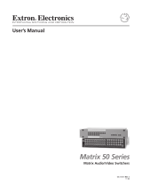
The matrix switcher is a single box solution (see figure 1 on page 2) to complex TP and
video signal routing applications. Each input and output is individually isolated and buffered.
Any input can be switched to any one or all outputs with virtually no crosstalk or signal noise
between channels. Multiple ties between inputs and outputs can exist simultaneously
The MTPX Plus series are available in a variety of matrix sizes (the matrix size is the number
of inputs and outputs):
•
MTPX Plus 816
(8 inputs by 16 outputs)
•
MTPX Plus 128
(12 inputs by 8 outputs)
•
MTPX Plus 168
(16 inputs by 8 outputs)
•
MTPX Plus 1616
(16 inputs by 16 outputs)
•
MTPX Plus 1632
(16 inputs by 32 outputs)
•
MTPX Plus 3216
(32 inputs by 16 outputs)
•
MTPX Plus 3232
(32 inputs by 32 outputs)
The MTPX Plus switchers input and output TP signals on RJ-45 connectors. A pr
e-peaking
feature on selected outputs allows you to boost the transmission distance of the output TP
signal.

MTPX Plus Series • Introduction 2
MT
P T SV A
OUTPUT
12V
0.5aMA
X
INPUT
L
R
S-VIDEO
INPUT
AUDIO
MONIT
O
R
POWER
12V
.5A MAX
OUTPUT
MT P T
1
5H D
A
PRE
-PEAK
ON
OFF
ETHER
N
ET
ACT
INPU
T
SELECT
LOCAL
RJ-45
LOCAL INPUTS
1
2 3 4 5
6
7
8
9
10
1
1 12
13 14 1
5
16
17 18 1
9
20
21
2
2 23 24 25 26
2
7 2
8
29
30 3
1 32
1
2
3
4 5
6 7 8 9
10
1
1 12
13
14 15 16
17 18 19
20
21 22 23
24
25 26
27 28
29
30 31 32
1
2
21 3
4
5
6
RS-232 OUTPUT INSERT
ION
LOCAL OUTPUTS OUTPUTS
I
NPUTS
CONTRO
L
MONO AUDIO OUTPU
TS
AUDIO INPUTS
LI
NK
R
E
SE
T
L
R
1
L R
2
L R
3
L
R
4
L R
5
L
R
6
L
R
1
L R
2
L R
3
L
R
4
L
R
5
L
R
6
L
R
7
L
R
8
T
xRx
1
T
x
Rx
2
TxRx
3
Tx
R
x
4
T
x
Rx
5
T
xR
x
6
T
xRx
7
Tx
Rx
8
Tx
Rx
9
T
xRx
10
Tx
Rx
11
T
xR
x
1
2
T
x
Rx
13
T
x
Rx
14
T
xRx
15
Tx
Rx
16
U
Sa
L
I
STED
1T23
I
.
T
.
E
.
®
POWER
12V
.5A MAX
INPU
T
RGB
1
MONO AUDIO
2
VID
Y/C
B-Y
Y
R
-Y
OUTPUTS
RS-232
Tx Rx
S
PACE
POWER
12V
.5A MAX
IN
PUT
RGB
1
MONO AUDIO
2
VID
Y/C
OUTPUTS
MT P U
R
A
COMPUTER IN
AUDIO IN
TCP/IP
Network
Extron
MTPX Plus 3232
Twisted Pair
Matrix Switcher
Control
System
Ext
ron
MT
P T SV A
T
ransmitter
DVD
Extron
MTP U R RSA SEQ
Universal Receiver
Extron
MTP U R A
Universal Receiver
Flat Panel Display
Extron
MTP T 15HD A D
Transmitter
PC
Extron
MTP T 15HD A
Transmitter
Rack Mounted PC
PC
Projector
Audio
RS 232
S-video
RGBHV
Audio
S-video
RGBHV
H
PA SERIE
S
A
U
D
I
O
P
OWER
AMP
L
I
F
I
E
R
1
2
L
I
M
IT
ER
/P
R
O
T
E
C
T
S
I
GN
A
L
O
V
E
R
TE
MP
Extron
SI 28
Surface-mount
Speakers
Extron
HPA 502
Audio Power
Am
Figure 1. Typical MTPX Plus Twisted Pair Matrix Switcher Application
Additionally, some inputs feature 15-pin HD and 5-pole 3.5 mm captive screw input
connectors for local RGB (VGA) and stereo audio inputs without an MTP transmitter. Some
outputs feature 15-pin HD output connectors and 5-pole 3.5 mm captive screw ports for
local RGB (VGA) and mono audio output without an MTP receiver. The local input and
output 15-pin HD connectors can also support HD-YUV video, YUV video, S-video, and
composite video.
NOTE: For most switchers, the local inputs are an option for use in place of the TP input
(input 1 can be either on the local connectors or the TP connector, for example).
For the MTPX Plus 128, four inputs are local only and eight inputs are TP only.
When audio is part of the TP input signal, the audio switching can either be linked with the
video (audio follow) or be independent of the video (audio breakaway). Adjustable input
audio gain and attenuation compensates for level differences between audio inputs.
NOTE: For low resolution MTPs (S-video and composite video) on the TP inputs, the
MTPX Plus audio circuits are compatible only with the newer generation, mono audio
models. See your MTP transmitter/ receiver and refer to the associated guide to
determine which MTP models you have.
The matrix switcher can be remotely controlled via its rear panel Remote port
(RS-232/RS-422 for most models, RS-232 only for MTPX Plus 128) and its front panel
Configuration port (RS-232 for most models, USB port for MTPX Plus 128) using either
Extron Windows®-based Matrix Switchers Control Program or the Simple Instruction Set
(SIS™). The SIS is a set of basic ASCII code commands that provides control through a
control system or PC without programming long, obscure strings of code.

MTPX Plus Series • Introduction 3
The switcher can be operated remotely by any of the following when that device is
connected to either MTPX Plus serial port:
• A control system
• A PC
• An Extron MKP 2000 remote control panel
• An Extron MKP 3000 remote control panel
For some outputs (most matrix sizes) or all outputs (MTPX Plus 128), bidirectional pass-
through RS-232 signals from a dedicated source (rather than from the selected input) can
be directly inserted into the signal set routed to the TP output. You can even route RS-232
on a link that is normally audio, such as to an MTP U R 15HD RSA SEQ receiver, which can
autodetect whether its signal input includes an audio component or an RS-232 component.
The matrix switchers are housed in metal enclosures. Most models have mounting flanges
for standard 19-inch racks built into the enclosure. The MTPX Plus 128 includes a kit for
rack mounting.
The switcher has an internal 100 VAC to 240 VAC, 50-60 Hz, 30 watt power supply that
provides worldwide power compatibility.
The MTPX Plus switcher has a minimum bandwidth of 300 MHz (-3 dB).
The switchers can also switch RGBS, RGsB, RsGsBs, HDTV, component video, S-video,
and composite video.

MTPX Plus Series • Introduction 4
TP Cable Advantages
Twisted pair cable is much smaller, lighter, more flexible, and less expensive than coaxial
cable. These TP products make cable runs simpler and less cumbersome. Termination of
the cable with RJ-45 connectors is simple, quick, and economical.
ATTENTION:
•
Do not connect this connector to a computer data or telecommunications network.
•
Ne connectez pas ces port à des données informatiques ou à un réseau de
télécommunications.
Transmission Distances
The maximum distances are determined by the frequency and resolution of the video signal
being routed and by which MTPX Plus inputs and outputs (TP or local) are in the full (video
source to display) routing path. The tables on the following pages specify the recommended
maximum transmission distances using Extron Enhanced Skew-Free™ A/V UTP cable or
UTP CAT 5, 5e, or 6 cable, terminated with RJ-45 connectors.
NOTES:
• For all three tables, the minimum TP cable length should be 25 feet (7.5 m).
• RS-232 serial communications can be sent up to 1,000 feet (300 m) from the MTP
transmitter output (or RS-232 output insert) to the MTP receiver TP input.
•
It is possible to exceed the r
ecommended distances; however, image quality may
be reduced.
• Daisy-chaining MTPX units by connecting a TP output from one matrix switcher to
the TP input of a second matrix switcher is not recommended. Daisy chaining in
this manner can lead to excessive video smearing.
• The transmitters, receivers, and matrix switcher are designed for and perform
best with Extron Enhanced Skew-Free A/V cable terminated in accordance with
the TIA/EIA T 568A wiring standard. CAT 5, 5e, and 6 cables are acceptable, but
less preferable. We also recommend the use of preterminated and tested cables.
Cables terminated on site should be tested before use to ensure that they comply
with Category 5 specifications.
• Daisy-chaining MTPX units by connecting a TP output from one matrix switcher to
the TP input of a second matrix switcher is not recommended. Daisy chaining in
this manner can lead to excessive video smearing.
•
The r
ecommendations shown in the tables apply equally for a transmission line that
consists of a single transmitter, the switcher, and receiver and for a transmission
line that encompasses a transmission daisy chain. For example, the maximum
suggested output range (MTPX Plus TP output to MTP receiver) for 1024 x 768
video is 450 feet (135 m) (table 1 [
2
]) or 500 feet (150 m) (table 2 [
4
]), whether
the transmission line consists of the switcher and a single receiver or the switcher
and three daisy-chained receivers. This range can be extended to 500 feet or 550
feet if the output is one that has the Pre-Peak function and the function is turned
on.
• For daisy-chained units, the first receiver in the chain should be at least 50 feet (15
m) from the switcher when the Pre-Peak feature is on.
• For daisy-chained units, any receiver in the chain closer than 350 feet (105 m)
may experience some form of over-peaking when the Pre-Peak switch is on. An
overpeaked image may appear bloomed.

MTPX Plus Series • Introduction 5
Table 1. Recommended maximum TP transmission distances at 60 Hz,
1
MTP transmitter to switcher when the display is on the MTPX Plus local (VGA)
output
ETHERNET
ACT
INPUT
SELECT
LOCAL
RJ-45
LOCAL INPUTS
1234 5678 910111213141516
17 18 19 20 21 22 23 24 25 26 27 28 29 30 31 32
1234 5678 910111213141516
17 18 19 20 21 22 23 24 25 26 27 28 29 30 31 32
1
2
213
456
RS-232 OUTPUT INSERTION
LOCAL OUTPUTS OUTPUTS
INPUTS
CONTROL
MONO AUDIO OUTPUTSAUDIO INPUTS
LINK
RESET
LR
1
LR
2
LR
3
LR
4
LR
5
LR
6
LR
1
LR
2
LR
3
LR
4
LR
5
LR
6
LR
7
LR
8
Tx Rx
1
Tx Rx
2
Tx Rx
3
Tx Rx
4
Tx Rx
5
Tx Rx
6
Tx Rx
7
Tx Rx
8
Tx Rx
9
Tx Rx
10
Tx Rx
11
Tx Rx
12
Tx Rx
13
Tx Rx
14
Tx Rx
15
Tx Rx
16
US
LISTED
1T23
I.T.E.
®
3.2A MAX
OUTPUT
INPUT
AUDIO
POWER
12V
.5A MAX
MONITOR
PRE-PEAK
ON
OFF
MTP T 15HD A
MTP Transmitter
1111111111
— or —
2
Switcher to MTP receiver when the video source is on the MTPX Plus local
(VGA) input
ETHERNET
ACT
INPUT
SELECT
LOCAL
RJ-45
LOCAL INPUTS
1234 5678 910111213141516
17 18 19 20 21 22 23 24 25 26 27 28 29 30 31 32
1234 5678 910111213141516
17 18 19 20 21 22 23 24 25 26 27 28 29 30 31 32
1
2
213
456
RS-232 OUTPUT INSERTION
LOCAL OUTPUTS OUTPUTS
INPUTS
CONTROL
MONO AUDIO OUTPUTSAUDIO INPUTS
LINK
RESET
LR
1
LR
2
LR
3
LR
4
LR
5
LR
6
LR
1
LR
2
LR
3
LR
4
LR
5
LR
6
LR
7
LR
8
Tx Rx
1
Tx Rx
2
Tx Rx
3
Tx Rx
4
Tx Rx
5
Tx Rx
6
Tx Rx
7
Tx Rx
8
Tx Rx
9
Tx Rx
10
Tx Rx
11
Tx Rx
12
Tx Rx
13
Tx Rx
14
Tx Rx
15
Tx Rx
16
US
LISTED
1T23
I.T.E.
®
3.2A MAX
INPUT
POWER
12V
0.5A MAX
RGB
VID
Y/C
OUTPUTS
MTP U R A
L
MONO AUDIO
R
MTP Receiver
2222222222
Video format Sending unit Pre-Peak Maximum distance
Off On
High quality
1
Variable
quality
2
Component,
S-video,
Composite
<300' (90 m) >350' (105 m) 800' (285 m) 1,000' (300 m)
640 x 480 <300' (90 m) >350' (105 m) 700' (215 m) 750' (230 m)
800 x 600 <300' (90 m) >350' (105 m) 550' (170 m) 650' (200 m)
1024 x 768* <300' (90 m) >350' (105 m) 500' (150 m) 600' (185 m)
1280 x 960* <300' (90 m) >350' (105 m) 400' (120 m) 500' (150 m)
1280 x 1024* <250' (75 m) >300' (90 m) 350' (105 m) 450' (135 m)
1360 x 765 <250' (75 m) >300' (90 m) 400' (120 m) 500' (150 m)
1365 x 768 <250' (75 m) >300' (90 m) 400' (120 m) 450' (135 m)
1366 x 768 <250' (75 m) >300' (90 m) 400' (120 m) 450' (135 m)
1440 x 900 <250' (75 m) >300' (90 m) 350' (105 m) 400' (120 m)
1400 x 1050 <250' (75 m) >300' (90 m) 350' (105 m) 400' (120 m)
1600 x 1200* <250' (75 m) >300' (90 m) 300' (90 m) 450' (135 m)
1920 x 1200 <250' (75 m) >300' (90 m) 300' (90 m) 400' (120 m)
HDTV 720p <250' (75 m) >300' (90 m) 400' (120 m) 500' (150 m)
HDTV 1080i <250' (75 m) >300' (90 m) 300' (90 m) 400' (120 m)
HDTV 1080p <250' (75 m) >300' (90 m) 300' (90 m) 400' (120 m)
NOTE: Resolutions marked with an asterisk (*) in this table have the same range
specifications at 75 Hz.

MTPX Plus Series • Introduction 6
Table 2. Recommended maximum TP transmission distances at 60 Hz, —
transmitter to receiver using MTPX Plus TP inputs and outputs
ETHERNET
ACT
INPUT
SELECT
LOCAL
RJ-45
LOCAL INPUTS
1234 5678 910111213141516
17 18 19 20 21 22 23 24 25 26 27 28 29 30 31 32
1234 5678 910111213141516
17 18 19 20 21 22 23 24 25 26 27 28 29 30 31 32
1
2
213
456
RS-232 OUTPUT INSERTION
LOCAL OUTPUTS OUTPUTS
INPUTS
CONTROL
MONO AUDIO OUTPUTSAUDIO INPUTS
LINK
RESET
LR
1
LR
2
LR
3
LR
4
LR
5
LR
6
LR
1
LR
2
LR
3
LR
4
LR
5
LR
6
LR
7
LR
8
Tx Rx
1
Tx Rx
2
Tx Rx
3
Tx Rx
4
Tx Rx
5
Tx Rx
6
Tx Rx
7
Tx Rx
8
Tx Rx
9
Tx Rx
10
Tx Rx
11
Tx Rx
12
Tx Rx
13
Tx Rx
14
Tx Rx
15
Tx Rx
16
US
LISTED
1T23
I.T.E.
®
3.2A MAX
INPUT
POWER
12V
0.5A MAX
RGB
VID
Y/C
OUTPUTS
MTP U R A
L
MONO AUDIO
R
MTP Transmitter
MTP Receiver
OUTPUT
INPUT
AUDIO
POWER
12V
.5A MAX
MONITOR
PRE-PEAK
ON
OFF
MTP T 15HD A
3333333333
44
44444444
Video format MTPX Pre-Peak Maximum distance
High quality Variable quality
Off On MTPX
input
3
MTPX
output
4
MTPX
input
3
MTPX
output
4
Component,
S-video
<300'
(90 m)
>350'
(105 m)
700'
(215 m)
700'
(215 m)
700'
(215 m)
800'
(245 m)
Composite
<300'
(90 m)
>350'
(105 m)
700'
(215 m)
700'
(215 m)
750'
(230 m)
750'
(230 m)
640 x 480
<300'
(90 m)
>350'
(105 m)
550'
(170 m)
600'
(185 m)
600'
(185 m)
650'
(200 m)
800 x 600
<300'
(90 m)
>350'
(105 m)
500'
(150 m)
500'
(150 m)
600'
(185 m)
600'
(185 m)
1024 x 768*
<300'
(90 m)
>350'
(105 m)
450'
(135 m)
450'
(135 m)
550'
(170 m)
550'
(170 m)
1280 x 960*
<300'
(90 m)
>350'
(105 m)
350'
(105 m)
350'
(105 m)
450'
(135 m)
450'
(135 m)
1280 x 1024*
<250'
(75 m)
>300'
(90 m)
350'
(105 m)
350'
(105 m)
450'
(135 m)
450'
(135 m)
1360 x 765
<250'
(75 m)
>300'
(90 m)
350'
(105 m)
350'
(105 m)
500'
(150 m)
500'
(150 m)
1365 x 768
<250'
(75 m)
>300'
(90 m)
350'
(105 m)
350'
(105 m)
450'
(135 m)
450'
(135 m)
1366 x 768
<250'
(75 m)
>300'
(90 m)
350'
(105 m)
350'
(105 m)
450'
(135 m)
450'
(135 m)
1440 x 900
<250'
(75 m)
>300'
(90 m)
350'
(105 m)
300'
(90 m)
400'
(120 m)
400'
(120 m)
1400 x 1050
<250'
(75 m)
>300'
(90 m)
350'
(105 m)
300'
(90 m)
400'
(120 m)
400'
(120 m)
1600 x 1200*
<250'
(75 m)
>300'
(90 m)
300'
(90 m)
300'
(90 m)
450'
(135 m)
450'
(135 m)
1920 x 1200
<200'
(60 m)
>250'
(75 m)
300'
(90 m)
250'
(75 m)
400'
(120 m)
400'
(120 m)
HDTV 720p
<250'
(75 m)
>300'
(90 m)
400'
(120 m)
400'
(120 m)
500'
(150 m)
500'
(150 m)
HDTV 1080i
<200'
(60 m)
>250'
(75 m)
300'
(90 m)
250'
(75 m)
400'
(120 m)
400'
(120 m)
HDTV 1080p
<200'
(60 m)
>250'
(75 m)
300'
(90 m)
250'
(75 m)
400'
(120 m)
400'
(120 m)
NOTE: Resolutions marked with an asterisk (*) in this table have the same range
specifications at 75 Hz.

MTPX Plus Series • Introduction 7
Table 3. Recommended maximum TP transmission distances at 60 Hz, —
VTT transmitter to VTR receiver using MTPX TP inputs and outputs
ETHERNET
ACT
INPUT
SELECT
LOCAL
RJ-45
LOCAL INPUTS
1234 5678 910111213141516
17 18 19 20 21 22 23 24 25 26 27 28 29 30 31 32
1234 5678 910111213141516
17 18 19 20 21 22 23 24 25 26 27 28 29 30 31 32
1
2
213
456
RS-232 OUTPUT INSERTION
LOCAL OUTPUTS OUTPUTS
INPUTS
CONTROL
MONO AUDIO OUTPUTSAUDIO INPUTS
LINK
RESET
LR
1
LR
2
LR
3
LR
4
LR
5
LR
6
LR
1
LR
2
LR
3
LR
4
LR
5
LR
6
LR
7
LR
8
Tx Rx
1
Tx Rx
2
Tx Rx
3
Tx Rx
4
Tx Rx
5
Tx Rx
6
Tx Rx
7
Tx Rx
8
Tx Rx
9
Tx Rx
10
Tx Rx
11
Tx Rx
12
Tx Rx
13
Tx Rx
14
Tx Rx
15
Tx Rx
16
US
LISTED
1T23
I.T.E.
®
3.2A MAX
POWER
VIDEO OUTPUT
9VDC-12VDC
500mA
RX
VTT Transmitter
VTR Receiver
POWER
VIDEO INPUT
9VDC-12VDC
500mA
TX
3333333333
44
44444444
Video format MTPX Pre-Peak Maximum distance
High quality Variable quality
Off On
MTPX
input
3
MTPX
output
4
MTPX
input
3
MTPX
output
4
640 x 480
<300'
(90 m)
>350'
(105 m)
400'
(120 m)
350'
(105 m)
400'
(120 m)
400'
(120 m)
800 x 600 <250'
(75 m)
>300'
(90 m)
350'
(105 m)
300'
(90 m)
400'
(120 m)
350'
(105 m)
1024 x 768 <150'
(45 m)
>200'
(60 m)
300'
(90 m)
300'
(90 m)
350'
(105 m)
350'
(105 m)
1280 x 960 <150'
(45 m)
>200'
(60 m)
250'
(75 m)
200'
(60 m)
300'
(90 m)
300'
(90 m)
1280 x 1024 <150'
(45 m)
>200'
(60 m)
250'
(75 m)
200'
(60 m)
300'
(90 m)
250'
(75 m)
1360 x 765 <150'
(45 m)
>200'
(60 m)
250'
(75 m)
200'
(60 m)
300'
(90 m)
250'
(75 m)
1365 x 768 <150'
(45 m)
>200'
(60 m)
250'
(75 m)
200'
(60 m)
300'
(90 m)
250'
(75 m)
1366 x 768 <150'
(45 m)
>200'
(60 m)
250'
(75 m)
200'
(60 m)
300'
(90 m)
250'
(75 m)
1440 x 900 <150'
(45 m)
>200'
(60 m)
200'
(60 m)
200'
(60 m)
250'
(75 m)
250'
(75 m)
1400 x 1050 <150'
(45 m)
>200'
(60 m)
200'
(60 m)
200'
(60 m)
250'
(75 m)
250'
(75 m)
1600 x 1200 <100'
(30 m)
>150'
(45 m)
200'
(60 m)
150'
(45 m)
250'
(75 m)
200'
(60 m)

MTPX Plus Series • Introduction 8
Skew Equalization
Skew exists between wire pairs when the physical length of one wire pair is different from
another. Skew affects the displayed image when the differential length between wire pairs
exceeds 2 feet. This causes the timing of the red, green, and blue video signals to appear
out of alignment (horizontal registration errors). The signals transmitted on the shortest
pair are shifted to the left if you are viewing white lines on a black background. A white
vertical line on a black field can appear as individual red, green, and blue lines that are close
together. The signal transmitted on the shortest wire pair leads the other colors and appears
to the left on the display. As the transmission cable length increases, the skew effect
increases.
The MTPX Plus has a skew equalizer function that is available using SIS, the
Matrix Switchers Control Program, or built-in HTML page control. The skew function
provides separate time delay circuits on the red, green, and blue video lines on the inputs
and the outputs. Each time delay circuit can be independently adjusted, from 0 to 62
nanoseconds, to properly align the red, green, and blue video signals on the displayed
image. When correctly set, the red, green, or blue video signal on the shortest wire pair is
delayed to properly converge the displayed video image.
UTP cable test equipment measures and reports wire pair length. The report on the various
pair lengths can be used to properly equalize pair skew. If UTP cable test measurement
cannot be done, pair skew can still be equalized by viewing a test pattern with a critical eye.
Examine the test pattern for loss of horizontal registration and, through a process of trial and
error, equalize any pair skew.
Features
• Twisted pair inputs and outputs — The switchers input and output TP signals on
female RJ-45 connectors.
NOTE: For low resolution MTPs (S-video and composite video) on the TP inputs,
the MTPX Plus audio circuits are compatible only with the newer generation, mono
audio models. See your MTP transmitter/ receiver and refer to the associated
guide to determine which MTP models you have.
• Local video inputs and outputs — The switchers directly input and output RGBHV
or RGBS (VGA) video on 15-pin HD connectors. They can also input and output RGsB,
RsGsBs, component/HDTV, S-video, or composite video.
• Local audio inputs — The switchers directly input balanced or unbalanced stereo
audio on 3.5 mm, 5-pole captive screw terminals.
• Audio input gain/attenuation — The volume of each audio input can be adjusted
so there are no noticeable volume differences between sources. You can set the input
level of audio gain or attenuation (-18 dB to +24 dB) via the front panel or via serial port
control.
• Audio output volume — The volume of each audio signal that is output on the 5-pole,
3.5 mm captive screw input connectors can be displayed and adjusted through a range
of full output to complete silence. Adjustments can be made from the front panel or
remote control.

MTPX Plus Series • Introduction 9
• Switching flexibility — The switcher provides individually buffered, independent,
matrix switched outputs with audio follow and audio breakaway.
• Tie any input to any or all outputs.
• Quick multiple tie — Multiple inputs can be switched to multiple outputs
simultaneously. This allows all displays (outputs) to change from source to source at
the same time.
• Audio follow — Audio can be switched with its corresponding video input via front
panel control or via serial port remote control.
• Audio breakaway — Audio can be broken away from its corresponding video
signal. This feature allows any audio signal to be tied to one or all outputs in any
combination with or without an accompanying video signal. Audio breakaway
switching can be done via front panel control or via serial port remote control.
• Operational flexibility — Operations such as input/output selection, setting of presets,
and adjustment of audio levels can be performed using the front panel or via the
Ethernet or either serial port. The serial ports allow remote control via a PC or a control
system. The Ethernet link allows multiple remote links with two levels of password
protection.
NOTE: The switcher is shipped password-protected. The factory configured
password for all accounts on this device have been set to the device serial
number.
• Front panel controls — The front panel controls support input and output
selection, preset creation and selection, audio gain and attenuation, and volume
control. The front panel features slots for labels that can identify each input and
output with text or graphics.
• Matrix Switchers Control Program — For serial port remote control from a PC,
the Extron Windows-based Matrix Switchers Control Program provides a graphical
interface and drag-and-drop/point-and-click operation. The Matrix Switchers
Control Program also has an emulation mode that lets you create a switcher
configuration file at the home office and then download it for use by the switcher on
site.
• Simple Instruction Set (SIS) — The remote control protocol uses the Extron SIS
for easy programming and operation.
• Remote control panels and keypads — The matrix switchers are remote
controllable, using the optional MKP 2000 and MKP 3000 remote control keypads.
These remote control devices are easy to use and provide tactile buttons for quick
selection. Each MKP can be used for input-to-output switching or one-touch
switching for a particular output. The MKP 3000 also can be used for selection of
global presets.

MTPX Plus Series • Introduction 10
• EDID Minder (MTPX Plus 128 only) — Captures and stored EDID information,
continuously making it available to all local inputs. EDID minder has two operating
modes:
• Automatic (default) — Captures EDID for displays connected to the local outputs
and provides data to the appropriate local inputs.
• User Assigned Mode — Rates from EDID table can be selected and assigned to
any input. EDID file for the display connected to output 1 can be stored in the EDID
table (4 user assigned locations available).
• Upgradeable firmware — The firmware that controls all switcher operations
can be upgraded in the field via either serial port, without taking the switcher out
of service. Firmware upgrades are available for download on the Extron website,
www.extron.com, and can be installed using the Matrix Switchers Control Program.
• Labeling — The Extron button label software is shipped with every Extron matrix
switcher. You can create labels to place above the front panel input buttons and below
the output buttons, with names, alphanumeric characters, or color bitmaps for easy and
intuitive input and output selection. Alternatively, labels can be made with any Brother
®
P-Touch
™
or comparable labeler.
• Global memory presets — 32 global memory presets are a time-saving feature that
lets you set up and store input/output configurations in advance. You can then recall
those configurations, when needed, with a few simple steps on the front panel.
• Rack mounting — The 1U high (MTPX Plus 128), 2U high (other matrix sizes 1616 and
smaller), or 3U high (matrix sizes 1632 and larger) enclosure is rack mountable in any
conventional 19-inch wide wide rack. The 2U and 3U enclosures are mountable without
extra hardware. The 1U enclosure is rack mountable using the provided mounting kit.
• Three front panel security lockout modes (Executive modes) — If a matrix
switcher is installed in an open area, where operation by unauthorized personnel may
be a problem, either of two security lockout modes can be implemented (the third mode
is unlocked). When a front panel lockout mode is enabled, a special button combination
or SIS command is required to unlock the front panel controls and make the front panel
fully operational.
• Power — The 100 VAC to 240 VAC internal power supply provides worldwide power
compatibility.

MTPX Plus Series • Installation 11
Installation
This section details the installation of the MTPX Plus Matrix Switchers, including:
• Mounting
• Rear Panel Cabling and Settings
• Front Panel Configuration Port
Mounting
ATTENTION:
•
Installation and service must be performed by authorized personnel only
.
• L’installation et l’entretien doivent être effectués par le personnel autorisé uniquement.
Detailed mounting instructions can be found in Mounting the Switcher on page 153. The
MTPX Plus switchers are housed in a 1U high (MTPX Plus 128), 2U high (matrix sizes 1616
and smaller), or 3U high (matrix sizes 1632 and larger) metal enclosures. The 1U enclosure
is rack mountable using the provided MBD 149 Through-desk and rack mounting kit. The
2U and 3U enclosures are mountable without extra hardware.
Rear Panel Cabling and Settings
Figure 2 shows the rear panel of the MTPX Plus 128.
100-240V 0.8A
50-60Hz
OUTPUTS
1
2
3
4
LOCAL INPUTS
INPUTS
1234
RESET
LAN
ACT
LINK
1
2
L
R2
L
R1
L
R4
L
R3
5678
1234
5678
Tx Rx
L
R2
L
R1
5 678
9101112
LOCAL OUTPUTS
RS-232 OUTPUT INSERT
REMOTE
RS-232
Tx Rx
Tx Rx Tx Rx
Tx Rx
AAA EEEFFFHHH III KKK LLLMMM GGGBBB CCC
Figure 2. MTPX Plus 128 Twisted Pair Matrix Switcher
A
Input (TP) ports (see page 13)
B
Local Input (VGA) ports
C
Audio Input (local) ports
D
Not present on this model
E
RS-232 Output Insert ports (see page 14)
F
Output (MTP) ports
G
Local Output (VGA) ports
H
Audio (local) outputs (see page 15)
I
Remote port
J
Not present on this model
K
LAN port (see page 16)
L
Reset button
M
AC power connector

MTPX Plus Series • Installation 12
Figure 3 shows the rear panel of the MTPX Plus 1616.
RESET
ETHERNET
ACT
LINK
MONO AUDIO OUTPUTS
OUTPUTS
RGB
RGB
1
2
3
Tx Rx
1
L
R
2
L
R
3
L
R
4
L
R
LOCAL INPUTS
RGB
RGB
LOCAL OUTPUT
INPUT
SELECT
ON
LOCAL
RJ - 45
123
RS-232/RS-422
REMOTE
CONTROL
RS - 232 OUTPUT INSERT
Tx Rx
Tx Rx
Tx Rx
Tx Rx
Tx Rx
Tx Rx
Tx Rx
1.6A MAX
LISTED
1T23
I.T.E.
AUDIO
INPUTS
1234 5678
910 11 12 13 14 15 16
1234 5678
910 11 12 13 14 15 16
12345678
AUDIO
AAA FFF
JJJ
KKK
LLL
HHHCCC
DDD EEEGGGBBB
MMM
Figure 3. MTPX Plus 1616 Twisted Pair Matrix Switcher
NOTE: The MTPX Plus 816 and MTPX Plus 168 are housed in the same 2U enclosure,
but have fewer input connectors (8 x 16 matrix) or output connectors (16 x 8 matrix) to
accommodate their smaller matrix sizes.
Figure 4 shows the rear panel of the MTPX Plus 3232.
ETHERNET
ACT
INPUT
SELECT
LOCAL
RJ-45
LOCAL INPUTS
1234 5678 910111213141516
17 18 19 20 21 22 23 24 25 26 27 28 29 30 31 32
1234 5678 910111213141516
17 18 19 20 21 22 23 24 25 26 27 28 29 30 31 32
1
2
213
456
RS-232 OUTPUT INSERTION
LOCAL OUTPUTS OUTPUTS
INPUTS
CONTROL
MONO AUDIO OUTPUTSAUDIO INPUTS
LINK
RESET
LR
1
LR
2
LR
3
LR
4
LR
5
LR
6
LR
1
LR
2
LR
3
LR
4
LR
5
LR
6
LR
7
LR
8
Tx Rx
1
Tx Rx
2
Tx Rx
3
Tx Rx
4
Tx Rx
5
Tx Rx
6
Tx Rx
7
Tx Rx
8
Tx Rx
9
Tx Rx
10
Tx Rx
11
Tx Rx
12
Tx Rx
13
Tx Rx
14
Tx Rx
15
Tx Rx
16
US
LISTED
1T23
I.T.E.
®
3.2A MAX
INPUTS
3.2A MAX
AAA
FFF
BBB GGG
CCC HHH KKKLLL JJJ
DDD
EEE
MMM
Figure 4. MTPX Plus 3232 Twisted Pair Matrix Switcher
NOTE: The MTPX Plus 1632 and MTPX Plus 3216 are housed in the same 3U
enclosure, but have fewer input connectors (16 x 32 matrix) or output connectors
(32 x 16 matrix) to accommodate their smaller matrix sizes.
A
Input (TP) ports (see page 13)
B
Local Input (VGA) ports
C
Audio Input (local) ports
D
Input select switches (see page 14)
E
RS-232 Output Insert ports
F
Output (MTP) ports
G
Local Output (VGA) ports
H
Audio (local) outputs (see page 15)
I
Not present on this model
J
Remote port
K
LAN port (see page 16)
L
Reset button
M
AC power connector
/