Page is loading ...

Setup Guide — YCS SW2 A
The Extron
®
YCS SW2 A is a two input, dual output
video and audio switcher with transcoding and
auto-input switching capabilities and digital time base
correction (TBC). This guide provides basic instructions
for setting up and operating the switcher.
Installation
Step 1 — Mount the unit
Mount the switcher on a rack shelf, furniture, or a projector pole mount if desired.
Step 2 — Connect video inputs
Connect composite video or S-video source devices to the Video, S-video, or
both input connectors.
Step 3 — Connect video outputs
Connect video output devices to the Video (composite), S-video, or both
output connectors.
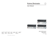
Step 4 — Connect audio inputs
a. Wire the RCA input connectors to audio sources as shown
in the diagram at right.
b. Connect the left stereo channels of the audio sources to
one or both white RCA Audio Input connectors.
Connect the right stereo channels of the audio input
sources to one or both red RCA Audio Input connectors.
Step 5 — Connect audio outputs
a. Wire the RCA audio output connectors to audio output devices as
shown in step 4a, above.
b. Connect the left stereo audio channels of the output devices to one
or both white RCA Audio Output connectors.
Connect the right stereo audio channels of the output devices to
one or both red RCA Audio Output connectors.
Step 6 — Wire the power connector (optional)
If using a different external power supply from the one provided with the YCS, wire the
included 2-pin captive screw connector to your power supply as shown below.
C
The power supply must not be permanently fixed to the building or similar structures.
The power supply must not be located within environmental air handling spaces or the
wall cavity.
The installation must be in accordance with the applicable provisions of the National
Electrical Code ANSI/NFPA 70, Article 725 and the Canadian Electrical Code,
Part 1, Section 16.
The power supply must be located within the same vicinity as the Extron A/V
processing equipment in an ordinary location, Pollution Degree 2, secured to a podium,
desk, or equipment rack in a dedicated closet.
(Continued on reverse side)
Tip (+)
Sleeve ( )
AUDIO
1
INPUTS
OUTPUT
2
L
R
R
L
VIDEO
VIDEO
S-VIDEO
INPUTS
OUTPUT
1
2
SECTION A–A
Ridges
Smooth
Power Supply Output Cord
A A
3/16” (5 mm) Max.

Setup Guide — YCS SW2 A, cont’d
Extron USA - West
Headquarters
+800.633.9 876
Inside USA / Canada Only
+1.714.491.1500
+1.714.491.1517 FA X
Extron USA - East
+800.633.9876
Inside USA / Canada Only
+1.919.863.1794
+1.919.863.1797 FAX
Extron Europe
+800.3987.6673
Inside Europe Only
+31.33.453.4040
+31.33.453.405 0 FA X
Extron Asia
+800.7339.8766
Inside Asia Only
+65.6383.4400
+65.6383.4664 FAX
Extron Japan
+81.3.3511.7655
+81.3.3511.7656 FAX
Extron China
+400.88 3.1568
Inside China Only
+86.21.3760.1568
+86.21.3760.1566 FAX
Extron Middle East
+971.4.2991800
+971.4.2991880 FA X
© 2010 Extron Electronics. All rights reserved.
www.extron.com
C
Always use a power supply specified by Extron for the YCS SW2 A. Use of
an unauthorized power supply voids all regulatory compliance certification
and may cause damage to the supply and the YCS.
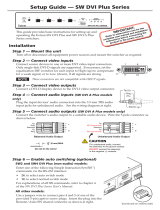
Step 7 — Enable auto-input switching (optional)
To set up the YCS to automatically select the active, connected input:
a. Use two jumper wires to connect pins 1 and 2 and pins 2 and
3 of the provided 3-pin captive screw connector. Tighten the
screws to hold the jumper wires securely in place.
b. Insert the captive screw plug into the Contact/Auto-SW
connector as shown at right.
Step 8 — Enable black and white mode (optional)
To enable the YCS to detect NTSC signals that are black and white only, place the switcher in
black and white mode as follows:
a. Remove the four case screws on the sides of the
unit and lift off the top cover.
b. Locate the jumper at JMP1 and SW1 on the YCS
internal board (behind the front panel buttons).
Place the jumper onto both the SW1 and JMP1
pins.
C
When placing the jumper on the two
pins, ensure that the fine wire connecting
the two sleeves of the jumper is at the top
(outside). Do not attempt to force the
pins through the wire.
c. Replace the case cover.
Step 9 — Power on
Apply power to the YCS, the input sources, and the output devices.
Selecting Inputs by Contact Closure
The Contact/Auto-SW connector on the YCS rear panel enables optional remote input
switching via a latching contact closure device (as
an alternative to auto-input switching, described in
step 7, above).
To switch inputs using contact closure:
a. Connect a latching contact closure device to
pins 1, 2, and _ of the Contact/Auto-SW
connector on the rear panel.
b. To select input 1, momentarily short pin 1 to
the _ pin. To select input 2, momentarily short
pin 2 to the _ pin.
Application Diagram
The figure at right provides an example of how a
YCS SW2 A switcher may be connected.
68-1446-50
Rev. A
02 10
JMP1
J26
CR5
SW1
Front
of Unit
Input 1 Button
1
2
VIDEO
VIDEO
AUDIO
S-VIDEO
CONTACT
AUTO-SW
POWER
12V
0.4A MAX
INPUTS
OUTPUT
1
1
INPUTS
OUTPUT
2
2
L
R
R
L
REMOTE
DVD
Projector
VCR
Extron
YCS SW2 A
Transcoding
Switcher with
Audio
Video
Audio
Audio
S-video
1
2
VIDEO
VIDEO
AUDIO
S-VIDEO
CONTACT
AUTO-SW
POWER
12V
0.4A MAX
INPUTS
OUTPUT
1
1
INPUTS
OUTPUT
2
2
L
R
R
L
REMOTE
M
E
N
U
E
N
T
E
R
C
A
N
C
E
L
SELECT
POWER
STATUS
ON
/
OFF
SOURCE
AUTO ADJUST
1 2
CONTACT
AUTO-SW
/