1
ELEKELEK
ELEKELEK
ELEK
TROTRO
TROTRO
TRO
Bauanleitung
Building instructions
Notice de construction
Instruzioni di montaggio
Instrucciones de montaje
F
GB
D
E
I
Best.-Nr.: 21 4164
Page is loading ...
Page is loading ...
Page is loading ...
Page is loading ...
Page is loading ...
Page is loading ...
Page is loading ...
Page is loading ...
Page is loading ...
Page is loading ...
Page is loading ...
Page is loading ...
Page is loading ...

15
Lfd. St. Bezeichnung Verwendung Material Abmessungen
57 1 Lager mit Gewinde Höhenruderlager Messing-Rohr Ø 3 x M5 x 17 mm
58 2 Stahldraht Höhenruder Federstahl Ø 3 x 130 mm
59 1 Druckstift Pendellock Höhenruder Kunststoff Fertigteil
60 1 Drucköse Pendellock Höhenruder Kunststoff Fertigteil
61 1 Stahldraht Kabinenhaube Stahl Ø 3 x 30 mm
62 1 GFK - Feder Kabinenhaube GFK 1,5 x 15 x 150 mm
63 5 Klettband Velourseite Kabinenhaube/Akku 30 x 60 mm
64 2 Klettband Hakenseite Akkurutsche 30 x 60 mm
Servorahmensatz
70 4 Servorahmen für Flaps / Querruder Tragflächen Kunststoff Spritzteil
71 2 Servorahmendeckel m. Hutze links / QR/Flaps Servorahmen Kunststoff Spritzteil
72 2 Servorahmendeckel m. Hutze rechts / QR/Flaps Servorahmen Kunststoff Spritzteil
73 16 Schrauben / Servorahmendeckel Servorahmen Stahl M 2 x 10 mm
Drahtsatz
80 2 Stahldraht / Ruderanlenkung Höhe / Seite Federstahl Ø 1,3 x 1400 mm
81 1 Seitenruderlager Seitenruder Alu-Draht Ø 2 x 400 mm
BUILDING INSTRUCTIONS
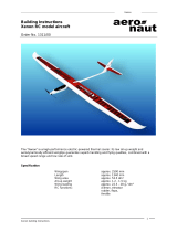
High-performance electric-powered glider Alpina 4001 Elektro Order No. 21 4164
Dear fellow modeller,
Kit contents (for details see Parts List)
1 Pair wing panels with full-contact spars, joiner system
installed. Finished leading edges, finished
aerodynamically efficient wingtips, machined wing servo
wells, sanded trailing edges. Aileron and camber-changing
flap lining strips in place under wing skins, machined
control surface hinge lines. Designed for optional airbrakes
(installation described).
1 GRP / CFRP fuselage with integral MULTIlock wing
retainer system, factory-fitted control sleeves and hard
white surface finish
1 CFRP canopy
1 Pair tailplane panels with finished leading edges, sanded
trailing edges, joiner system installed, finished tips
1 Rudder, finished
1 Bag wooden parts including machined servo plate
1 Bag top-quality small hardware items
1 Bundle wire and rod
1 High-quality steel wing joiner rod
1 Name placard sticker set
1 Set building instructions
Specification: Alpina 4001 ELEKTRO
Wingspan: 4001 mm
Fuselage length: 1690 mm
Wing area (FAI): 80.6 dm²
Weight, according to
finish and fittings: approx. 4900 g
Wing loading (FAI): approx. 61 g/dm²
Wing section: RG sections, mod.
Tailplane section: NACA 0009
Congratulations on your choice of the Alpina 4001
ELEKTRO high-performance electric glider. This model
offers an excellent performance, and we hope you will
thoroughly enjoy building and flying it.
MULTIPLEX model kits are subject to constant quality
checks throughout the production process, and we
sincerely hope that you are happy with the contents of your
kit. However, we would ask you to check all the parts before
you start construction, as we cannot exchange
components which you have already worked on. If you
find any part is not acceptable for any reason, we will
readily correct or exchange it. Just send the component to
our Model Department; please be sure to include a brief
description of the fault.
We are constantly working on improving our models, and
for this reason we must reserve the right to change the kit
contents in terms of shape or dimensions of parts,
technology, materials and fittings, without prior notification.
Please understand that we cannot entertain claims against
us if the kit contents do not agree in every respect with the
instructions and the illustrations.
Caution!
Radio-controlled models, and especially model aircraft,
are by no means playthings. Building and operating
them safely requires a certain level of technical
competence and manual skill, together with discipline
and a responsible attitude at the flying field.
Errors and carelessness in building and flying the model
can result in serious personal injury and damage to
property. Since we, as manufacturers, have no control
over the construction, maintenance and operation of
our products, we wish to take this opportunity to point
out these hazards, and to emphasise your personal
responsibility.

16
RC functions
Ailerons 2 servos
min. 15 Ncm
Elevator 1 servo
*30 Ncm
Rudder 1 servo
*30 Ncm
Camber-changing flaps 2 servos
min. 15 Ncm
Optional airbrakes 2 servos
15 Ncm
Brushless controller
*for mechanical reasons only
Receiving system components
We recommend Micro digi servos, MPX Order No. 6 5378,
for the ailerons and camber-changing flaps of the Alpina
4001 ELEKTRO.
For the optional airbrakes two additional Micro digi servos
are required, although in this case lower-cost servos are
adequate, e.g. MULTIPLEX Cockpit digi, Order No. 6 5385;
in this case the installation frame will need to be slightly
modified.
The servo plate is designed to accommodate two MICRO
digi servos, Order No. 6 5378 (elevator and rudder), and
the On/Off switch.
It is important that the receiver battery should be of
generous capacity to cope with the model’s receiving
system, bearing in mind that you will be using 6 servos. We
recommend at least a 4-cell 1500 mAh NiMH pack: Order
No. 15 6007. If you want a little “more”, then by all means
increase the capacity, but you must not add an extra cell.
The servo plate opening is designed to take a switch
harness with integral charge socket, MPX Order No. 8
5039. Two extension leads, MPX Order No. 8 5111 and
MPX Order No. 8 5031, are also required.
There is plenty of space in the fuselage for the receiver on
the rear part of the battery tray.
For the electrical connection between the wing-mounted
aileron and airbrake servos and the receiver we
recommend three Cable Sets 2, MPX Order No. 8 5253.
Important note
For all joints involving the styrofoam wing cores it is
essential that you do not use solvent-based adhesives,
and in particular avoid instant or cyano-acrylate glue
(cyano, or CA). These materials will melt and destroy a
large volume of foam, and the component will be
completely ruined. Use solvent-free adhesives such as
5-minute epoxy or white glue.
Notes on using epoxy laminating resin
Epoxy laminating resin is not a proper adhesive as it
stands. However, you can make a variety of excellent
adhesives by mixing additives into it; by careful choice of
filler you can match the characteristics of the adhesive to
the requirements of the moment.
1. Chopped cotton fibres, Order No. 60 2738, produce a
tough but flexible joint.
2. Superfine glassfibres, Order No. 60 2784, produce a
rock-hard joint which is easy to sand.
3. Micro-balloons, Order No. 60 2779/80, convert the resin
into a lightweight filler paste.
4. The special thixotropic agent, Order No. 60 2782, makes
all the adhesives and fillers listed above thixotropic, i.e.
prevents them running off a vertical surface.
The Alpina 4001 ELEKTRO
The kit you have just purchased includes every item you
need to complete the basic airframe, including linkage
hardware, but does not include adhesives.
A few words on the history of the Alpina 4001 ELEKTRO:
The Alpina was first introduced in the early 1980’s, since
which time its outstanding flying characteristics have
made it a familiar and popular model amongst the gliding
fraternity both in Germany and abroad. The design has
been flown in dozens of competitions, and has indeed
won many of them. In the early 90’s the Alpina Magic was
added to the line, its main innovation being variable
wingspan.
The model’s large size makes it easy to see in the air, and
this allows the pilot to fly safely over a very wide radius. In
practice this means that the area over which the pilot can
seek thermal assistance is much larger than with smaller
models. Its low minimum sink rate and outstanding circling
characteristics (for thermal flying) even give the Alpina
4001 a good chance of holding its own against specialised
lightweight soarers in light-wind conditions.
The model’s broad speed range makes it easy to cross
large areas of poor air quickly and easily, and you do not
need to fear turbulent conditions and stormy weather.
The Alpina 4001 is so manoeuvrable that you could be
forgiven for thinking it was a much smaller model. As a
result this glider can be flown from quite small slopes and
offers exciting potential for aerobatics.
Many modellers have also expressed a wish for an electric
version of the Alpina 4001. Quite a number of Alpinas have
been converted by individual modellers, and Multiplex staff
members have also had excellent experience with their
own conversions. This made us confident about producing
the
Alpina 4001 ELEKTRO.
With our conversion the all-up weight of the Alpina 4001
ELEKTRO is no higher than that of the “standard” glider
version. This guarantees the same superb flying
characteristics as the pure soarer.
If you intend flying the Alpina 4001 primarily from a flat field
site you can safely manage without airbrakes, as the
proven butterfly
(“crow”) landing system provides accurate
spot landing capability when set up correctly.
If you wish to install airbrakes anyway, we recommend
fitting 370 mm Contest airbrakes, MPX Order No. 72 2646.
It is possible to install airbrakes even in a finished model,
and the kit includes full fitting instructions together with the
wooden parts required.

17
So - let’s get down to work.
Fuselage
We will start by completing the fuselage 3, as this is the
reference point for all the other components.
Fuselage openings / wing fairing
The first step is to open up all the fuselage openings at the
marked points. Carefully drill 3 mm Ø holes at the four pilot-
hole positions at the wing root using a twist drill. Using the
same tool drill a series of adjacent holes in the openings
for the wing joiner, and file the holes out to the final size of
15 mm Ø using a round file.
[Fig. 1]
Compression struts
Compression struts are fitted between the wing roots at
the leading and trailing edge to prevent fuselage damage
when the wings swing forward in a hard landing. One
hardwood strut 16 (10 x 10 x 85 mm) is fitted at the trailing
edge position, behind the rear locating peg. The strut must
be trimmed carefully to length to avoid pushing the fuselage
out of shape. Fit an identical strut at the leading edge,
again cutting carefully to length.
Ensure that the compression struts do not push the
fuselage out of shape; they must neither force the moulding
wider or narrower. Fit the struts temporarily, then plug in
the wings and check the fit. You may need to make slight
adjustments to allow for manufacturing tolerances. The
front compression strut should not be glued in place
permanently until the sockets for the aileron and airbrake
servo connections have been installed, otherwise access
will be restricted.
To fit the rear compression strut we recommend that you
spear it on a length of steel rod. Glue the strut in place, then
twist the rod out again when the epoxy has cured.
[Fig. 2]
Preparing the servo plate
Adjust the openings in the servo plate 11 if necessary to
suit your servos and the On/Off switch for your receiver.
When selecting servos please note that the space below
the servo plate is limited.
Temporarily install the servos and slide the servo plate to
and fro until it fits snugly in the fuselage. The rear edge of
the servo plate should be located about 230 mm aft of the
tip of the fuselage nose.
Do not glue the plate in place yet; the motor has to be
installed first.
Installing the motor
The first step is to attach the motor / gearbox assembly to
the motor bulkhead 10. For safety’s sake it is a good idea
to tape over the motor openings. Now trim the motor
bulkhead so that the motor fits accurately, i.e. so that the
spinner lines up correctly with the fuselage nose when
fitted on the motor shaft. There should about 1 mm
clearance between spinner and fuselage.
Don’t forget to sand all joint positions inside the fuselage
before applying glue.
When you are confident that everything fits accurately,
apply a few drops of 5-minute epoxy between motor
bulkhead and fuselage flange. Fit the motor and the
spinner again, and tape everything in place while the glue
cures. When the epoxy is hard carefully “unwrap” the motor
/ spinner once more.
Without disturbing the bulkhead, carefully remove the
motor so that you can reinforce the joint: apply thickened
laminating resin all round the joint between the motor
bulkhead 10 and the fuselage, inside and out. Take care
not to get epoxy on the motor mounting surface. The
thickened resin can easily be guided into the correct
position using a paintbrush dipped in paint thinners. Allow
the epoxy to cure fully, then install the motor assembly
again.
Preparing the battery tray and former
Tack the former 12 in place in the fuselage using cyano;
it should be 230 mm from the point of the nose. Assemble
the battery tray from the pre-sawn plywood plate 13 (3 x 65
x 460 mm) and the obechi strips 14 (5 x 10 x 410 mm). Glue
the two strips flush with the edges of the plate using cyano,
as shown in Fig. 3.
Trial-fit the battery tray; the rear end should engage under
the air outlets, and rest on the former at the front. Drill 1.5
mm Ø pilot-holes through the battery tray into the former
as shown in Fig. 5. Open up the holes in the battery tray to
2.5 mm Ø.
[Fig. 3]
[ Drill out to 2.5 mm Ø ]
Servo plate
Temporarily install the servos. Position the plate under the
former 12 at the one end.
[Fig. 4]
Tack the servo plate to the fuselage using a few drops of
cyano, then remove the servos again. Roughen up the
fuselage sides above the servo plate using 80-grit (coarse)
abrasive paper. Mix up thickened epoxy resin and glue the
plate in place securely, applying a fillet of resin all along
the joints. A good method of obtaining a really strong joint
is to apply a layer of glass cloth (about 100 g/dm²) over the
servo plate and up the fuselage sides. When the epoxy has
cured cut off the excess glass at the ends of the plate and
inside the servo apertures. Clean up the servo plate and
install the servos again. The “snake outers” are fixed to the
former 12 using thickened epoxy after aligning them with
the servo output arms.
Installing the battery tray
The battery tray is fixed to the former 12 using two self-
tapping
screws 52 and the rubber grommets 53. To clamp
the battery in place glue two strips of Velcro (hook-and-
loop) tape 64 (hook side) to the tray. A strong rubber band
should be wrapped round battery and tray to ensure that
the pack does not come adrift from the Velcro.
[Fig. 5]

18
Carbon canopy
This canopy provides an eye-catching focal point for the
model, and reduces work on the cabin area to a minimum.
There is no need to trial-fit and trim the canopy, as required
with standard vacuum-moulded versions.
The canopy 4 is held on the fuselage at the front using a
steel pin 61. At the rear a flat GRP strip 62 is used, acting
as a retaining spring.
Fix the GRP spring to the inside of the canopy as shown
in Fig. 6, leaving it projecting by 10 mm at the rear end of
the canopy. Glue it in place permanently using thickened
epoxy and two layers of glass cloth (approx. 100 g/dm²).The
GRP spring should be glued over a length of 50 to 60 mm.
Don’t forget to roughen the joint surfaces using 80-grit
abrasive paper beforehand.
Glue the locating peg 61 to the channeled strip 15 using
thickened epoxy, leaving it projecting by about 13 mm.
Allow the epoxy to set hard, then glue the channeled strip
to the inside of the canopy. Position the strip about 18 mm
aft of the front edge of the canopy.
To make up the difference in thickness between the
vacuum-moulded canopy / frame and the carbon canopy,
strips of self-adhesive Velcro tape 63 (loop) are applied to
the inside of the carbon canopy, as shown in Fig. 6.
[Fig. 6]
Cut down the centre of the Velcro loop strips 63 with a pair
of scissors.
Apply the strips to the inside of the canopy as shown: one
strip at the lower canopy edge front and rear on both sides.
The fuselage canopy recess now has to be prepared to
accept the front locating peg. File a notch in the flange
using a round file and adjust it gradually until the canopy
is a perfect fit.
Caution: work slowly here, as it is very easy to file away too
much material.
Wing / fuselage fit
The Alpina 4001 ELEKTRO features a free-floating wing
joiner system.
This means that the wing joiner does not touch the
fuselage. The openings in the fuselage for the spar joiner
should be about 1.5 mm larger all round than the joiner
itself. File the holes out if necessary to provide proper
clearance.
This method of attaching the wings is standard practice in
full-size aircraft building, and has already proved excellent
in many MULTIPLEX models.
The wing joiner 48 takes the form of an extremely strong
12 mm Ø spring steel rod.
The fuselage is suspended between the wings on four
pins. Don’t worry about their size - the pins have a total
sheer strength of more than one ton! Please work carefully
when drilling the pin holes as they determine the accuracy
of the wing location.
[Fig. 7]
[glider version only]
Using small screw-clamps carefully fix small pieces of 3
mm scrap plywood to the top and bottom surfaces of the
wing at the leading and trailing edges to act as stop pieces
when positioning the wing against the root fairing. These
locating pieces should overlap the fuselage root fairing by
about 3 mm at the top only.
Position one wing carefully (at leading edge and trailing
edge), tape it in place, and mark the position of the pin
holes on the wing root rib working through the fuselage
from the opposite side, using a length of 3 mm Ø steel rod
filed to a point. Repeat the procedure with the other wing.
Drill the holes in the root ribs using a 3 mm twist drill.
Remember to take the dihedral into account; the holes
should be drilled parallel to the wing joiner. The locating
pins 49 can be glued in place once both wing panels have
been prepared to this stage. Round off one end of the pins
and sand them thoroughly where they are to be glued.
Apply mould-release wax (ordinary wax polish will do) to
the fuselage at the wing root position, and glue the pins in
place using slow-setting epoxy - UHU-Plus or similar.
About half the length of the pins must project out of the wing
roots, and please note that it makes for easier assembly
at the flying field if the pins are of different length front and
rear. Align the fuselage and wings carefully, tape them
together and leave the resin to cure overnight. Remove the
screw clamps and scrap wood.
We maintain tight manufacturing tolerances, but
nevertheless there is always a chance of minor
discrepancies in the fit between the wing and the fuselage
root fairing. Any minor gaps and slight mis-fits are easily
corrected.
Installing the all-moving tailplane bearing
The tailplane bearing exploits technology which has proved
to be an outstanding success in many MULTIPLEX models
over a number of years. This professional solution to an
old problem is based on precision-made machined parts,
accurate to 1/100 mm, and this is the system used in the
Alpina 4001 ELEKTRO. The high-quality bearing prevents
the tailplane wobbling in the wind as a result of slop, and
also provides a really strong, load-bearing joint between
fuselage and tailplane. It represents the final, professional
solution to the problem of bonding the bearing to the
fuselage.
[Fig. 8]
1. Screw one of the two tailplane bearing nuts 56 on the
threaded pivot bush 57, set it flush with the end and lock
it in place with a drop of cyano.
2. Open up the holes for the tailplane
bearing in the fin and
clean them up on the inside of the moulding. Carefully
roughen up the joint surfaces inside the 12 mm Ø external
recesses in the fin.
3. Open up the curved slots for the rear tailplane joiner rod.
4. Solder a clevis 40 to the steel elevator pushrod 80 (1.3
mm Ø x 1400 mm).
5. Prepare the 3 mm Ø steel rods 58 which form the
tailplane joiners. Round the ends off carefully and shorten
them if necessary. Connect the clevis 40 to the third hole
from the bottom of the tailplane crank 54 and slip the
pushrod into the snake outer from the tail end. Temporarily

19
assemble and install the parts of the tailplane bearing and
plug in the tailplane panels.
6. Check that it is possible to set the tailplane at 90° to the
fin and file out the holes if necessary until this is the case.
Remove the bearing parts again. Apply slow-setting epoxy
(e.g. UHU plus / endfest 300) sparingly to the prepared nut
and slide it into the hole in the fuselage. Fit the bush 55 onto
it inside the fuselage and slip the tailplane crank 54 onto
the bush. Now fit the bush on the other side through the
fuselage. Apply epoxy to the second nut 56 and screw the
parts together.
Tip: apply wide parcel tape over both sides of the fin around
the bearing area and cut through it to expose the external
recesses only. This ensures that any excess epoxy is
smeared on the tape rather than the fuselage.
Plug the tailplane panels into the fuselage and set up the
model as shown in Fig. 9. Leave the epoxy to harden
overnight.
[Fig. 9]
All-moving tail lock - holding the tailplane panels together
You all know the problem: all-moving tailplane panels
tend to slide outwards along the joiner rods. This is very
dangerous, and also looks awful. Now we can put an end
to it once and for all!
The position of the tail lock unit is marked on the fuselage.
[Fig. 10]
Installation:
Drill and file out a slot about 5 - 6 mm wide in both sides
of the fuselage inside the marked line. The length of the
slot varies according to the travel of the tailplane, and
should be no larger than necessary.
Apply wide parcel tape over both sides of the fin around the
tail lock area and cut through it with a sharp knife to expose
the slots only. This ensures that any excess epoxy is
smeared on the tape rather than the fin.
[Fig. 11]
Snap the parts of the tail lock together and fit the tailplane
panels on the fuselage using the steel joiner rods - no glue
at this stage. Check and adjust the tail lock as necessary.
When everything fits correctly glue the female part 60 of the
tail lock in one tail panel using thickened 5-minute epoxy
(glass powder) - the projecting length should be half the
distance between the installed tail panels. Take care that
no glue gets onto the spring leaves; it is a good idea to wrap
them in tape, and remove the tape again later. The tail lock
must be parallel to the joiner rods. Allow the glue to set
hard, then push the male section 59 into the female
section 60 until it snaps into place.
Now plug the tailplane panel with the tail lock inserted into
the fuselage. Apply glue to the hole in the other tailplane
panel. Guide the male section of the tail lock assembly into
the hole when you push the second panel into place, then
set the tailplane to full up-travel and leave the epoxy to set
hard; if you neglect to do this it will be stiff to move later.
Handling: to disengage the tail lock grasp each tail panel
in one hand and pull them smartly apart. The latch will
disengage, and the panels can be pulled off in the normal
way. If you wish to increase the holding power of the snap
lock you can fit a narrow ring (about 2 mm wide) of heat-
shrink sleeving round the female section and shrink it in
place.
Fin, rudder and tail post
A tail post is integrated into the fin in the manufacturing
process to prevent the moulding developing a warp.
1. Open up the rudder pushrod shroud using a round file
of 8 - 10 mm Ø.
2. File a semi-circular recess in the top of the fin to clear
the rudder leading edge.
3. Open up the machined holes for the rudder hinge lugs
51.
4. Trim the hinge lug slots in the leading edge of the rudder;
a small rotary cutter works very well here, but a sharp knife
and a small bradawl also do the job. Engage the rudder
lugs 82 in the rudder pivot tube.
5. Glue the hinge lugs in the tail post 16. Align the parts
accurately before leaving the resin to set hard.
[Fig. 12]
Installing the ring-screw (rudder horn)
To fit the ring-screw 44 drill a 4 mm Ø hole in the rudder,
drilling as far as the opposite skin. The hole should be
central relative to the pushrod shroud, and as close as
possible to the pivot axis of the rudder, so that the linkage
point is exactly at 90° to the pushrod line and the hinge axis.
Remove the foam inside the hole over a radius of about 10
mm; the easy way to do this is to bend a piece of wire at
an angle, heat the end with a match and melt the foam out.
Shorten the ring-screw to the point where the pushrod just
has clearance inside the shroud when the pushrod is
operated.
When the final surface finish has been applied, glue the
ring-screw in the hole using plenty of UHU Plus Endfest
300. This is done by filling the whole of the void under the
rudder skin with epoxy. Heat up the epoxy slightly using a
heat-gun to make it less viscous, and apply it to the hole
drop by drop with a piece of steel wire. Push the ring-screw
into the hole, align it carefully and wipe away excess resin.
Completing the wing panels
In spite of the high level of pre-fabrication a certain amount
of work remains to be done on the wing panels.
Installing the wing-mounted servo frames
Check that the servo frames fit snugly, and remove just
enough foam on one side to accommodate the servo
connector. The frames for the aileron and camber-changing
flap servos should be installed in such a way that the
bottom of the servos face the fuselage.
[Fig. 13]
Apply a layer of 100 g/dm² glass cloth to the floor of the well
to prevent the servo deforming the top wing skin. Use a
minimum of resin here; only a little is required, and if you
use too much you may find that there is insufficient depth
for the servo frame.
The servo frames can now be glued in place: first screw
the cover to the frame and mask off the wing surface
(uncovered version only) with wide parcel tape. This avoids
the problem of excess glue soiling the surface, and
reduces finishing to a minimum. Glue the frames in place

20
and wipe off excess epoxy with methylated spirit on a cloth.
Allow the resin to set hard then remove the parcel tape,
unscrew the cover and sand the area flush using a long
sanding block (uncovered version).
Separating the ailerons and camber-changing flaps
To avoid transport damage the control surfaces are supplied
still attached to the wings. Using a fine hacksaw blade (for
a straight, clean cut), saw out the surfaces at right-angles
to the fuselage centreline. At the inboard (fuselage) end
leave a fixed panel about 95 mm long attached to the wing.
The camber-changing flap should be about 850 mm long,
and the aileron 900 mm long. Do not leave a fixed portion
between the aileron and flap. Glue the plywood end lining
pieces to the cut faces of the wing and control surfaces,
remembering to take the thickness of the plywood into
account when cutting the control surfaces to final length.
There should be a gap about 0.5 - 1 mm wide between the
flaps and ailerons.
[Fig. 14]
Installing the wing retainer system
The wings are held against the fuselage using the
MULTIlock system. The wings can be fitted to the fuselage
quickly and easily, but are adequately secure while the
model is in flight.
To disengage the MULTIlock system and dismantle the
model, grip the wing with finger and thumb at the spar
position (i.e. wrap your hand around the root leading edge)
and hold the fuselage against your body. A brief tug at the
wing will release the MULTIlock system, and the wings
can then be slid off in the usual way.
[Fig. 15]
Fix the MULTIlock sockets 47 in the fuselage with a drop
of cyano. The MULTIlock plugs 46 have to be installed in
the wings.
Mask off the fuselage root fairing with wide parcel tape and
apply mould-release wax to the area around the wing
retainer. Push the retainer plug 46 into the fuselage-
mounted socket. Plug in the wing and check that the
retainer can be sunk completely into the wing root.
TIP: If you need to separate the retainer plug from the
fuselage before gluing it in place, the easiest method is
to use a pair of pincers: grip the retainer plug by the
innermost groove and “roll” the pincers along the fuselage
root fairing to disconnect the retainer.
Apply plenty of thickened 5-minute epoxy to the hole in the
wing root, plug the wing in and tape it in place. Remember
to fit the MULTIlock plug before you do this! Allow the resin
to set hard, then release the wing from the fuselage as
described above.
Installing the ring-screws (aileron / flap horns)
The horns are installed as described for the rudder horn,
although in this case it may be necessary to remove a little
of the lining strip below the skin. A small rotary cutter is very
useful here, although it is also possible to use a small
sharp bradawl.
To provide adequate aileron movement the ring-screws
should be shortened by 5 mm. For the camber-changing
flaps use the horns full-length.
[Fig. 15]
Installing the film hinges
This model is designed for tape hinges, i.e. the finished
ailerons and camber-changing flaps are attached to the
wing with adhesive tape. One long strip is applied to the
top surface, and a second in the slot on the underside. This
method of attaching control surfaces has proved durable
and efficient in the long-term.
Unfortunately there is a tendency for the strips of tape to
“float” over the course of several months due to unequal
pressure in storage and warming up at the flying field. The
hinge is then no longer efficient, and the resultant “step”
can look unsightly. This problem can be eliminated by
fitting supplementary plastic film hinges. However, they
can only fulfil their purpose if the pivot axis of the hinge is
located exactly at the pivot axis of the control surface.
Fit three film hinges 50 in each control surface - in each
case one should be immediately adjacent to the horn.
Cut a slot for the hinge starting exactly at the point of the
hinge pivot line, cutting into the lining strip at an angle of
about 45° to the top surface. The best tool for this is a thin
diamond-tip grinding wheel mounted in a 12-Volt electric
drill. You can use a junior hacksaw blade to clean up the
slot and adjust it to fit the hinge. If the slot gets too wide and
the hinge is a loose fit, pack it up on the underside with a
strip of thin plywood.
Caution: the film hinges are simply pushed into their
slots; don’t glue them!
[Fig. 16]
Installing the (optional) airbrakes
If you intend to fly your Alpina 4001 ELEKTRO
predominantly from the slope we recommend that you
install 370 mm Contest airbrakes, MPX Order No. 72 2646.
The first step is to install the airbrake servo frame in the
underside of the wings.
[Fig. 17]
Installing the airbrake servo frames
Mark the position of the servo frame on the underside of
the wing skin and cut through the skin and the foam core
with a sharp craft knife.
[Fig. 18]
Note that a small section of the airbrake servo box must
be sawn out so that the pushrod can be installed “under
the skin”.
[Fig. 19]
Glue the servo frames in the wing as described in the
section “Installing the wing-mounted servo frames”.
To install the airbrake units first mask out the appropriate
area on the top wing skin with a strip of wide parcel tape.
Mark the position of the airbrake as accurately as possible
using a narrow-tip waterproof felt-tip pen. Hold the bottom
section of the airbrake on the wing skin, top side down, and
cut out the wing skin (20 x 370 mm) using a sharp balsa
knife. Carefully remove the foam core down to the bottom
skin, leaving a neat slot. This is best done using light
pressure and a gentle sawing motion to achieve a clean
cut.

21
[Fig.20]
Trim the airbrake support strips 17 to fit on the sides of the
airbrake bottom sections and attach them with a little 5-
minute epoxy. Now trim the airbrake bottom sections to fit
in the slot in such a way that the top edge of the unit is about
1.5 mm below the wing skin. This is done by sanding back
the underside of the airbrake support strips.
Glue the bottom airbrake section in the wing using 5-
minute epoxy.
Trim the airbrake well surround strips 18 to fit, glue them
in place using a little 5-minute epoxy and remove the
parcel tape from the wing while the glue is still soft. Allow
the epoxy to set hard, then sand back the surround strips
flush with the wing skin.
The airbrake pushrods are made from the remainder of
the elevator and rudder pushrod material. Solder a clevis
onto one end of each rod.
Now assemble and install the linkage and the Contest
airbrake actuating arm following the instructions supplied
with the brakes. Leave the top blade off at first, as this gives
better access to the mechanism. Install the pushrod from
the airbrake end, cut it to length and connect it to the
airbrake unit. Check that the linkage works correctly and
freely, and make any adjustments required. Remove a
little foam in the area of the servo output arm to clear the
clevis, and solder the clevis to the pushrod. Check that the
servo and the airbrake are in the centre position when you
do this. Connect the clevis to the third hole from the inside
of the servo output arm and cut off excess output arm
material.
Tip: a good alternative is to fit a threaded coupler at one end
of each pushrod at the airbrake end, as this allows you to
make fine adjustments at any time from within the airbrake
box. To do this you just have to remove the top brake blade.
Install the airbrake servo, connect it and fit a plain servo
frame cover (no pushrod fairing). Install the airbrake
blades.
Attaching the airbrake capstrip
Trim the airbrake capstrip 19 to fit in the opening, sand it
about 0.5 mm narrower all round and attach it to the
retracted airbrake using a little 5-minute epoxy or double-
sided adhesive tape. Check that the system works correctly
and adjust if necessary. Sand the airbrake capstrip flush
with the wing surface with the brake retracted. Work very
gently here and take great care not to strain the mechanism
or the blades, otherwise you could distort the airbrake and
cause it to malfunction.
If your model is the uncovered version you now have to
decide whether to paint the wings or apply iron-on film.
Film: just sand the wing surfaces smooth overall.
Leave the trailing edge about 1 - 1.5 mm thick. On no
account round off the trailing edge, as a thicker square-
edged trailing edge is almost as efficient as a razor-sharp
one, but much more durable in everyday flying - especially
if you cover the wing with film.
Paint: the alternative method of finishing your Alpina 4001
ELEKTRO is to apply glass cloth and resin and then paint
the surfaces (see later for more details). This is the only
route to take if you are aiming at top performance and an
outstanding finish.
Sand the wing surfaces clean and even, aiming to smooth
out and maintain the airfoil section as accurately as
possible. Use a sanding block at least 30 cm long, and
preferably 50 cm long. Make sure that the sanding block
is perfectly straight and stick the abrasive paper to it using
double-sided tape. The best type of abrasive “paper” in our
experience is the abrasive band designed for use with
band sanders. It is slightly more expensive than the usual
type, but lasts much longer. Sand in long strokes, using
light but even pressure, and use a figure-of-eight motion.
This completes the basic assembly procedure.
Installing the radio control system
Installing the servos and control linkages in the fuselage
If you have not already done so, this is the time to install
the elevator and rudder servos.
Solder a clevis 40 securely to the rudder end of the rudder
pushrod 80. At the servo end solder a threaded coupler 41
and fit a locknut 45 and clevis 40.
Solder a threaded coupler 41 to the servo end of the
elevator pushrod and fit a locknut 45 and clevis 40.
Connect the clevises in such a way that full servo travel
can be exploited.
The snake outers for the elevator and rudder pushrods are
located at the servo end using pieces of the channeled
strip 17, which are glued to the fuselage.
Installing the wing-mounted servos and linkages
Install the servos in the servo frames, cut the threaded
pushrods
42 to length if necessary and screw the clevises
40 on the ends. Lock the clevises at the servo end with a
drop of cyano glue, and lock the other clevises with the
M2.5 locknuts 45, so that you can make adjustments as
required.
If your model features airbrakes, install the airbrake
servos and connect the pushrods.
If your radio control system is unable to supply the airbrake
signal to two separate outputs, you may have to install one
airbrake servo with the output arm pointing at the bottom
wing skin. In this case install the servo at the appropriate
depth in the wing and secure it carefully.
It is a good idea to carry out basic adjustments to the radio
control system at this early stage. Please note: the full
travel of the servos should always be exploited!
Attach the servo frame covers 71 and 72 using the screws
73.
Electrical connection, wing / fuselage
The Alpina 4001 ELEKTRO has four or six wing-mounted
servos which have to be connected to the receiver. They
are connected at the fuselage / wing transition using grey
5-pin MPX plugs and sockets; the wings and the fuselage
are designed for these connectors as standard. All the
wing-mounted servo cables should be fitted with
separation filters as shown in the diagram. Cable sets
including all the parts required together with detailed
instructions are available under the following Order
Numbers:
If connecting:
4 servos Cable Set 2, MPX Order No. 8 5256
6 servos Cable Set 1, MPX Order No. 8 5255
in
addition

22
If you prefer different connectors please be sure to
select the best quality you can find. All contacts should
be gold-plated.
Connect all the positive wires to a common connector pin,
and do the same with all the negative wires to a different
pin. A separate contact is required for each signal wire.
If you have to connect three servos for each wing you will
need to use all the contacts of the 5-pin plug (1 x positive,
1 x negative and 3 x signal).
The connectors are installed as a non-flexible plug-in
system which couples automatically when you fit the
wings on the fuselage. Don’t worry about the lack of “flex”
- we have been using this system for more than 20 years
without any failures. Loose cable connections tend much
more often to result in fractured wires. Complete the wiring
to the connectors by soldering the joints carefully and
insulating them individually with heat-shrink sleeving,
then install the sockets flush with the outside of the
fuselage and secure them with thickened epoxy applied
from the inside. When the resin has cured connect the pre-
wired plug from the wing and check that it fits in the wing
root. When everything fits correctly, glue the plug in the
wing root using thickened 5-minute epoxy again.
[Fig. 21]
[Laenge = Length]
There is space on the battery tray for the receiver. Fix the
receiver to the plate using Velcro (hook-and-loop) tape
(MPX Order No. 68 3112). The adhesive on the tape does
not stick well to wood, so fix the “hook” tape to the plate
using cyano. Slip the aerial into a snake outer, tie a knot
in the end and leave the sleeve loose in the tail boom.
The capacity of the receiver battery should be
commensurate with the model and its intended use, so
please be sure to select a battery of adequate size, bearing
in mind that the model carries at least 6 servos. We
recommend a pack consisting of at least four 1.5 Ah NiMH
cells, Order No. # 15 6007.
Your model is now complete.
Nevertheless, there are a few important points to be
checked while you are still in the workshop:
Centre of Gravity (balance point) and longitudinal dihedral.
Provided that you get these two settings right you will
encounter no problems in test-flying your new model and
in general flying.
Successful test flying always boils down to good
preparation.
At Multiplex the CG and longitudinal dihedral are first
determined theoretically, then checked and confirmed as
part of the practical flight testing programme.
A CG position of 100 mm, measured from the wing root
leading edge, has been found to be ideal for this model.
The easy way of checking this accurately it to use the
Centre of Gravity balance, MPX Order No. 69 3054.
A longitudinal dihedral of 1.0° has proved just right for the
Alpina 4001 ELEKTRO, and this can be checked using the
incidence gauge, MPX Order No. 69 3053.
We strongly recommend that you stick to these settings.
The control surface travels stated below have been
established as the ideal values during practical test flying,
and have been confirmed by several experienced model
pilots. Set these travels for the time being, and alter them
as and when you see fit. We are confident that you will never
need to change them.
Alpina 4001 ELEKTRO control surface travels
All control surface travels are measured at the widest point
of the surface, and are stated below in millimetres. The
elevator travels are also stated in degrees, so that you can
check the travel using the incidence gauge.
Input down / up
Aileron servos
Aileron 12 / 22
Flap (slider) 2 / 1
Flap (switch) 2 / 1
Spoiler (butterfly) 0 / 20
Input down / up
Camber-changing flap servos
Aileron 0 / 10
Flap (slider) 2 / 1
Flap (switch) 2 / 1
Spoiler (butterfly) 25 / 0
Input down / up
Elevator servo
Elevator 6° 10 / 10
Flap (slider) 1 / 1
Throttle (motor) 1 - 1.5 / 0
Spoiler (butterfly) 1.5 - 2.5 / 0
Input right / left
Rudder servo
Rudder 45 / 45
Now your Alpina 4001 ELEKTRO is ready for the air!
The first flight
The “old hands” amongst you will now be eager for the first
opportunity to take your new Alpina 4001 ELEKTRO to the
flying site, where you will test-fly it in the accustomed
manner, carry out any minor corrections required, and
then, we hope, have many hours of pleasure flying your
new model.
The following is intended to help the less experienced
modeller to test-fly and trim the model correctly, and to
exploit the model’s fine performance to the full.
Test flying
Every flying machine, from the humble chuck glider to the
full-size aircraft, has to be test-flown and trimmed after
completion; your Alpina 4001 ELEKTRO is no exception.
The slightest inaccuracy in construction can lead to a
minor variation in the model’s flight characteristics and
control response. Test-flying is the process of optimising
the CG, and of fine-tuning the model’s control response.
Avoid at all costs repeated hand-glides at a flat field site
with the motor stopped. The most dangerous time for any

23
model is when it is close to the ground, and hand launches
are therefore by their nature extremely hazardous. There
is hardly any time to correct the controls, and a hard landing
can easily damage the model.
Range testing (for experts too!)
Ensure that your transmitter and receiver batteries are
freshly charged according to the battery manufacturer’s
recommendations. Before switching on your transmitter
make certain that your channel is vacant. The channel
pennant on your transmitter aerial is obligatory, and shows
other pilots what frequency you are using. If there are other
pilots present, tell them loud and clear what channel you
are on, and find out what frequencies they are using.
Before the first flight you should carry out a range check,
and we strongly recommend that you repeat the test before
the start of every day’s flying. Hold the model in such a way
that your body cannot mask or otherwise influence the
receiver aerial.
A friend should collapse the transmitter aerial fully (but
leave it attached), then walk away from you carrying the
transmitter.
As the range increases your colleague should operate
one transmitter function constantly while you watch the
model’s control surfaces. The servos not being moved
should remain motionless up to a range of about 80 m,
and the moving servo should follow the stick deflections
immediately and smoothly. Repeat the test with the motor
running. Even when close to the limit of ground range the
motor must respond immediately when you switch it off
from the transmitter.
This test can only be carried out successfully if the radio
band is not suffering interference, and if no other RC
transmitters are switched on - even on different channels!
Note that in high mountain areas extreme field strengths
and excessive range of other transmitters make such
checking procedures worthless.
If you are not sure the system is working correctly, please
don’t risk a flight - even if you are dying to fly the new glider
and your mates are egging you on. Check first that your
channel really is vacant. If so, and if the problem persists,
pack up your entire RC system (complete with batteries,
switch harness and servos) and send it back to the
equipment manufacturer for checking.
Faults don’t cure themselves!
The first flight
At the slope or at a flat field site
Set the motor running at full power and give your Alpina
4001 ELEKTRO a powerful hand-launch, with the wings
level and the nose angled slightly up. Immediately correct
the climb angle if necessary, and adjust the trims for a
straight climb. It may be necessary to mix in a little elevator,
depending on the power of the electric motor system you
have fitted.
At the slope you should wait for a period of reliable lift and
launch the model with the wings level and the nose down.
Don’t worry if the model dives at first - it will pick up speed
rapidly, and speed is half the battle! If necessary adjust the
trims to achieve straight flight and a reasonable cruising
speed. The next step is to fly turns and circles in both
directions in order to test the model’s turning
characteristics, the harmonisation between ailerons,
elevator and rudder, and the degree of aileron differential.
Be sure to try out the airbrakes or crow brakes at a
reasonable height so that you are ready for any pitch trim
change on the landing approach.
Checking the Centre of Gravity (always with motor switched
off)
The procedure for CG testing described here is a method
of fine-tuning the model’s balance. It can only work when
air movements are slight, and when the initial CG position
is approximately correct. It is bound to fail if the model is
way out of balance and/or there is a strong wind. In windy
conditions it is difficult to set up the model for normal cruise
speed, as it is hard to judge the model’s speed relative to
the surrounding air.
Trim the model carefully for normal cruising speed, which
should be comfortably above stalling speed. The model
should show no tendency to “hunt” up and down, or mush
along close to the stall. It should respond normally to all
controls. The camber-changing flaps should be at neutral.
Now - assuming that you have plenty of height in hand -
apply down-elevator briefly to place the model in a vertical
dive. Immediately centre the stick and watch the model
carefully. If it recovers to normal flight in a broad, gentle
curving arc (100 m) by itself, without ballooning up above
the horizontal, then the CG is correct.
If the model bounces up again immediately and climbs
strongly, the CG is too far forward.
Remove a small amount of lead ballast (min. 20 g, max.
40 g) from the nose, apply a little down-trim and repeat the
test.
If the model shows no tendency to recover by itself - the dive
may even become steeper - the CG is too far aft.
Immediately recover the model with gentle up-elevator.
Add a small amount of lead (min. 20 g, max. 50 g) to the
fuselage nose, fix it securely, and apply a little up-trim.
Repeat the test.
Once you have established the optimum CG position it is
best to remove any additional nose ballast and correct the
CG by adjusting the position of the flight battery.
Thermal flying
We assume that the electric motor is used just as a self-
launching aid, and that for the rest of the flight the model
will be flown as a pure glider.
Making the best use of flat field thermals is not particularly
easy, and calls for considerable skill and experience.
Areas of rising air are harder to detect and recognise at a
flat field because they tend to occur at higher altitude than
at the hillside, where it is often possible to find lift while the
model is cruising along the edge of the slope and then
circle away in it. A thermal at a flat field which occurs directly
overhead is very hard to recognise, and to exploit it to the
full requires a highly skilled pilot. For this reason it is
always best to go thermal seeking off to one side of where
you are standing.
You can recognise thermal contact by the model’s
behaviour. Good thermals are obvious because the model
will climb strongly, but weak thermals take a practised eye

24
to detect, and you will need a lot of skill to make use of them.
With a little practice you will be able to recognise likely
trigger points for thermals in the local landscape. The
ground warms up in the sun’s heat, but heat absorption
varies according to the type of terrain and the angle of the
sun’s rays. The air over the warmer ground becomes
warmer in turn, and the mass of warm air flows along close
to the ground, driven by the breeze. Strong winds usually
prevent thermal build-up. Any obstruction - a shrub or tree,
a fence, the edge of a wood, a hill, a passing car, even your
own model on the landing approach - may cause this
warm air to leave the ground and rise. Imagine a drop of
water on the ceiling, wandering around aimlessly, and
initially staying stuck to the ceiling. If it strikes an obstruction
it will fall on your head. A triggered thermal can be thought
of as the opposite of the drop of water.
The most obvious thermal triggers include sharply defined
snow fields on mountain slopes. The air above the snow
field is cooled, and flows downhill; at the edge of the snow
field, part-way down the valley, the cool air meets warm air
flowing gently uphill, and pushes it up and away as if cut
off by a knife. The result is an extremely powerful but bumpy
thermal bubble. Your task is to locate the rising warm air
and centre your model in it. You will need to control the
model constantly to keep it centred, as you can expect the
most rapid climb rate in the core of the thermal. Once
again, this technique does demand some skill.
To avoid losing sight of the model be sure to leave the
thermal in good time. Remember that a glider is always
easier to see under a cloud than against a clear blue sky.
If you have to lose height in a hurry, do bear the following
in mind:
The structural strength of the Alpina 4001 ELEKTRO is
very great, but it is not infinite. You can fetch your model
down from virtually any altitude at an angle of 45° with the
airbrakes extended. If you want to try speed runs in F3B-
style, then the camber-changing flaps must be kept at
neutral.
Set up your landing approach with plenty of height in hand,
and extend the airbrakes to achieve a steep final approach
so that the model is close to the ground for the minimum
period of time. The “regulation” square approach,
consisting of downwind leg away from you, cross-wind leg
and a straight approach with airbrakes extended or butterfly
system deployed and final flare will help preserve the
model, the pilot and any spectators.
Flying at the slope
Ridge soaring is an extremely attractive form of model
flying. Flying for hours on end in slope lift, without needing
any outside aid for launching, must be one of the finest of
modelling experiences. But to “milk” a thermal to the limits
of vision, bring it down again in a continuous series of
aerobatic manoeuvres, and then to repeat the whole show
- that must surely be the last word in model flying.
But take care - there are dangers for your model lurking at
the slope. Firstly, in most cases landing is much more
difficult than at a flat field site. It is usually necessary to land
in the lee of the hill where the air is turbulent; this calls for
concentration and a high-speed approach with last-minute
airbrake extension. A landing on the slope face, i.e. right
in the slope lift, is even more difficult. Here the trick is to
approach slightly downwind, up the slope, and flare at
exactly the right moment, just before touch-down.
Safety
Safety is the First Commandment when flying any model
aircraft. Third party insurance should be considered a
basic essential. If you join a model club suitable cover will
usually be available through the organisation. It is your
personal responsibility to ensure that your insurance is
adequate.
Make it your job to keep your models and your radio control
system in perfect order at all times. Check the correct
charging procedure for the NC batteries used in your RC
set. Make use of all sensible safety systems and
precautions which are advised for your system. An excellent
source of practical accessories is the MULTIPLEX main
catalogue, as our products are designed and manufactured
exclusively by practising modellers for other practising
modellers.
Always fly with a responsible attitude. You may think that
flying low over other people’s heads is proof of your piloting
skill; others know better. The real expert does not need to
prove himself in such childish ways. Let other pilots know
that this is what you think too. Always fly in such a way that
you do not endanger yourself or others. Bear in mind that
even the best RC system in the world is subject to outside
interference. No matter how many years of accident-free
flying you have under your belt, you have no idea what will
happen in the next minute.
The fascination of it all
Model flying is, and always has been, a fascinating hobby,
and a thoroughly enjoyable way of spending your leisure
hours. Take your time to get to know your new Alpina 4001
ELEKTRO really well. Plan to spend many hours in the
open air, where you will learn to appreciate the model’s
outstanding performance and its docile handling. You can
join us in enjoying one of the few types of sport which
combine high technology, manual dexterity, and
sophisticated personal skills. You can fly alone or with
friends, and at the same time you can enjoy the pleasures
of nature - treats which have become rare in today’s world.
We - the MULTIPLEX team - wish you many hours of
pleasure in building and flying your new model. Happy
landings!
MULTIPLEX Modelltechnik GmbH
Model Development Dept.

25
Appendix
1. Tissue covering, followed by a painted finish; this
method of finishing requires thorough initial sealing of all
wooden surfaces using standard sanding sealer, with
fine sanding between coats. The tissue is applied using
the sealer or clear shrinking dope. Lay the tissue on the
surface dry and apply sealer or dope through it to stick it
to the prepared surface. Be careful to avoid bubbles and
creases. Several more coats of sanding sealer and fine
sanding eventually form a good surface for a painted
finish. On no account apply the coloured paint directly to the
prepared or (even worse) bare wood surface. Apply several
brushed or sprayed coats of colour paint, with fine sanding
(wet-and-dry paper, used wet) between coats. A final light
coat will produce a glossy finish which can then be
polished to give an efficient high-gloss surface. However,
bear in mind that this method is extremely labour-intensive,
and unfortunately the finish is quite easily damaged.
2.) The technique of applying a finish using glass cloth
and resin is described in full detail in our “Resin Primer”
book, Order No. 60 2768, which includes many practical
tips. We strongly recommend that you study this book,
which also provides much valuable information on other
areas of modelling where the modern material of glassfibre-
reinforced plastic (GRP) is beneficial.
3.) Covering with heat-shrink film is the quickest and most
effective finishing method, and gives outstanding results
in terms of appearance, practicality and durability. Just
follow the instructions supplied with the film. Learning
how to apply film is not difficult; provided that you follow the
instructions to the letter even your first wing will be a
complete success.
Important:
When covering with iron-on film it is essential to ensure
that the foam core is not overheated, as this can result in
damage (distortion). Some films require a high processing
temperature, and if you are using these types of film you
must take particular care when applying the material. The
guarantee does not cover damage to the flying surfaces
caused in this way.
Some practical tips on film covering
The usual method of applying film is to tack the edges in
place, trim the film to shape, iron the edges down firmly,
then heat the film with a heat gun to shrink it, and rub it down
onto the wood with a soft cloth. This method is effective, but
does have one drawback. No matter how carefully you
sand the surface and remove every trace of dust, you
cannot remove the wood’s natural grain texture. When you
rub the warm film down with a soft cloth, the material is
pressed into the surface texture, and inevitably follows the
microscopic ridges and grooves of the wood. The result
is a less smooth surface than you might have expected.
This effect can be eliminated in the following way: instead
of the soft cloth, take a thick piece of balsa - similar to a
sanding block - and stretch a piece of stiff fabric over it as
follows: place the block on the fabric, pull the sides up, and
staple the material down on the top of the block. If you now
rub the film down with the smooth side of this block (your
hand will be a comfortable distance from the heat gun) the
film will not follow the tiny grooves in the wood, and you will
usually achieve a highly efficient super-smooth surface,
approaching that of a moulded GRP wing panel.
The ailerons and camber-changing flaps are usually
attached to the wings using hinge tape. However, it is
possible to use the film itself as
a hinge. The result can
be every bit as good as a tape hinge. This is only possible
if you have followed the instructions to the letter and
produced really sharp, perfectly straight mating edges on
the wing and the control surface. The top and bottom film
must weld together along the pivot line, and this is only
possible if the edges are really sharp.
The first step is to cover the underside of the wing in the
usual way. Apply film to the control surface as well, but do
not finish the job; simply tack down the edges, trim the film
to size, and iron the edges down (i.e. do not use the heat-
gun). Leave excess film at the ends and especially at the
front (at least 5 cm). Pull the excess round the ends, iron
it down and trim it off neatly. You now have a control surface
sitting on the bench, underside film-covered, not yet shrunk,
and with a wide excess of film running along the whole
length of the leading edge.
Place the wing on the bench resting on its leading edge,
top surface facing you; support it in this position. Lay the
projecting film on the wing recess sealing strip and pull it
tight, so that the flaperon hangs down, resting on the top
surface of the wing. Centre the control surface in the
recess and spot-fix the film in place using the tip of the iron.
Set the aileron to neutral (centre) and check the end gaps
in the wing recess. You may find that several attempts are
necessary to obtain identical end gaps. Pull the film taut
so that the aileron is pulled into the correct position against
the wing, and iron the film into place. Cut off the excess film
and iron the edge down permanently. If the control surface
is now brought to the neutral position it should be possible
to see a narrow strip of film between wing and control
surface from above. Fold the control surface onto the top
of the wing again and shrink the film on the underside of
the control surface. This protects the underside of the wing
from heat. Cover the top surface of the wing in the usual
way. Trim the film and iron down the cut edges. Iron the film
down firmly on both sides of the hinge line, then cut through
the film on both sides of the gap from the underside, using
a very sharp knife. The control surface will now be free to
move again. Now comes the most important step: iron
down the film 5 mm from the pivot line on the wing and the
control surface, holding the control surface in the extreme
“down” position. After this run the iron over the whole of the
pivot line to weld the bottom film to the top film. Fold the
control surface right up and back, and repeat the process
on the underside.
When finishing the job with the heat gun, take a little care
when working close to the control surface to avoid loosening
the film hinge. If it does come loose you will need to repeat
the last stage. When you are finished, the control surface

26
will be hinged permanently and invisibly to the wing, and
will move freely up and down.
Applying the decals
Cut out the decals and apply them to the model.
There are two convenient methods of applying the individual
decals included in the decor set, both of which enable you
to position the decal accurately: the strip method and the
water method.
For smaller items we recommend the strip method: using
sharp scissors cut out the decal, leaving an even excess
about 1 - 2 mm wide all round. Release the backing paper
on one edge and cut a strip about 5 mm wide from it. Place
the decal on the model and position it carefully, holding the
exposed strip away from the surface. When you are happy,
press the exposed strip down. Fold the decal back on itself
so that you can peel off the remaining backing paper
starting from the stuck edge. At the same time rub the decal
down onto the model with your other hand, starting from
the edge already in place. For larger decals the strip
method can only be recommended to the highly skilled
modeller; generally speaking the water method is safer.
The surface to be decorated must be waterproof. Mix a
squirt of household liquid detergent into a bowl of water,
and dampen the surface of the model with the solution. Cut
out the decal as before, leaving an even excess about 1 -
2 mm wide all round, and remove about one third of the
backing paper. Position the decal carefully, then peel away
the remaining backing paper. Lay the decal down on the
model. You will find that the water prevents the adhesive
sticking, and the decal can be moved around to position
it accurately. Wipe out any air bubbles and excess water,
working from the centre of the decal outwards. The residual
moisture will diffuse away in a day or two, after which the
decal will adhere in the usual way. In the meantime it is
best not to touch the decal.
Parts list Alpina 4001 ELEKTRO
Part No. Description Purpose Material Dimensions
No. off
1 1 Building instructions Paper A4
2 1 Decal set (name placard) Printed film Ready made
3 1 Epoxy fuselage White GRP Ready made
4 1 Canopy Carbon fibre Ready made
5 1 Pair of wing panels Foam / obechi Ready made
6 1 Pair of tailplane panels Foam / obechi / balsa Ready made
7 1 Rudder Foam / obechi Ready made
Wooden parts
10 1 Motor bulkhead Fuselage Birch ply Machined
11 1 Servo plate Fuselage Plywood Machined
12 1 Former Fuselage Obechi Machined, 14 thick
13 1 Battery tray, bottom Fuselage Plywood Pre-sawn, 3 mm
14 2 Battery tray, side reinforcement Fuselage Obechi 10 x 5 x 410 mm
15 1 Channeled strip, canopy Fuselage Obechi Pre-sawn
16 1 Compression strut, front / rear Fuselage Obechi 10 x 10 x 85 mm
17 4 Airbrake support strip Wings Balsa 5 x 20 x 370 mm
18 4 Airbrake surround strip Wings Lime 1.8 x 4 x 380 mm
19 2 Airbrake capstrip Wings Obechi 1.8 x 12 x 380 mm
Hardware items
40 12 Metal clevis Control linkages Steel M2.5
41 2 Threaded coupler Control linkages Brass M2.5
42 2 Threaded rod Control linkages Steel M2.5 x 40 mm
43 2 Threaded rod Control linkages Steel M2.5 x 65 mm
44 5 Ring-screw (horn) Control surfaces Aluminium M4
45 6 Hexagon nut Clevis locknut Brass M2.5
46 2 MULTIlock plug Wing retainer Plastic Inj. moulded
47 2 MULTIlock socket (in fuselage) Wing retainer Plastic Inj. moulded
48 1 Wing joiner rod Wings Spring steel 12 Ø x 330 mm
49 4 Steel rod Wing locating pin Spring steel 3 Ø x 60 mm
50 12 Plastic film hinge (2 x 6 off) Aileron / flap Plastic Ready made
51 3 Snap-fit hinge lug Rudder Plastic Inj. moulded
52 2 Self-tapping screw Battery tray Steel 2.2 Ø x 13 mm
53 2 Rubber grommet Battery tray Rubber Ready made
54 1 All-moving tailplane crank Fuselage Plastic Inj. moulded
55 1 Brass tube Tailplane bearing Brass 6 Ø x 0.45 x 5 mm
56 2 Bearing nut Tailplane bearing Aluminium Ready made
57 1 Threaded bush Tailplane bearing Brass tube 3 Ø x M5 x 17 mm
Page is loading ...
Page is loading ...
Page is loading ...
Page is loading ...
Page is loading ...
Page is loading ...
Page is loading ...
Page is loading ...
Page is loading ...
Page is loading ...
Page is loading ...
Page is loading ...
Page is loading ...
Page is loading ...
Page is loading ...
Page is loading ...
Page is loading ...
Page is loading ...
Page is loading ...
Page is loading ...
Page is loading ...
Page is loading ...
Page is loading ...
Page is loading ...
Page is loading ...
Page is loading ...
Page is loading ...
Page is loading ...
Page is loading ...
Page is loading ...
Page is loading ...
Page is loading ...
Page is loading ...
Page is loading ...
Page is loading ...
Page is loading ...
Page is loading ...
Page is loading ...
/