Page is loading ...

%ODFN2:KLWH#/&'#0LQL07RXFK#3DQHOV
+)LUPZDUH#YHUVLRQ#*5#RU#ORZHU,
,QVWUXFWLRQ#0DQXDO
818¨#0LQL07RXFK#3DQHOV#DQG#$FFHVVRULHV

Limited Warranty and Disclaimer
AMX Corporation warrants its products to be free from defects in material and
workmanship under normal use for a period of three years from date of purchase
from AMX, with the following exceptions. Electroluminescent and LCD control
panels are warranted for a period of three years, except for the display and touch
overlay components, which are warranted for a period of one year. Disk drive
mechanisms, pan/tilt heads, codecs, power supplies, modifications, MX Series
products, and KC Series products are warranted for a period of one year. Unless
otherwise specified, OEM and custom products are covered for a period of one year.
AMX software products are warranted for a period of 90 days. Batteries and
incandescent lamps are not covered.
This warranty extends to products purchased directly from AMX or an authorized
AMX dealer. Consumers should inquire from selling dealer as to the nature and
extent of the dealer’s warranty, if any.
AMX is not liable for any damages caused by its products or for the failure of its
products to perform, including any lost profits, lost savings, incidental damages, or
consequential damages. AMX is not liable for any claim made by a third party or
made by you for a third party.
This limitation of liability applies whether damages are sought, or a claim is made,
under this warranty or as a tort claim (including negligence and strict product
liability), a contract claim, or any other claim. This limitation of liability cannot be
waived or amended by any person. This limitation of liability will be effective even
if AMX or an authorized representative of AMX has been advised of the possibility
of any such damages. This limitation of liability, however, will not apply to claims
for personal injury.
Some states do not allow a limitation of how long an implied warranty lasts. Some
states do not allow the limitation or exclusion of incidental or consequential
damages for consumer products. In such states, the limitation or exclusion of the
Limited Warranty may not apply to you. This Limited Warranty gives you specific
legal rights. You may also have other rights that may vary from state to state. You
are advised to consult applicable state laws for full determination of your rights.
EXCEPT AS EXPRESSLY SET FORTH IN THIS WARRANTY, AMX MAKES NO OTHER
WARRANTIES, EXPRESSED OR IMPLIED, INCLUDING ANY IMPLIED WARRANTIES OF
MERCHANTABILITY OR FITNESS FOR A PARTICULAR PURPOSE. AMX EXPRESSLY
DISCLAIMS ALL WARRANTIES NOT STATED IN THIS LIMITED WARRANTY. ANY IMPLIED
WARRANTIES THAT MAY BE IMPOSED BY LAW ARE LIMITED TO THE TERMS OF THIS
LIMITED WARRANTY.

Black/White LCD Mini-Touch Panels Table of Contents i
Table of Contents
Introduction ............................................................................ 1
Overview 1
What's New 2
Features 2
Applications 3
What's in this Manual 4
Installing the Mini-Touch Panel ............................................. 5
Overview 5
Mounting the Mini-Touch Panels 5
AXU-MLC (/PB) and low profile back box 5
AXU-MLC (/PB) and BB-MTP
(solid surfaces) 7
AXU-MLC (/PB) and BB-MTP
(plasterboard) 9
AXM-MLC (rack mount) 11
AXW-MLC (/PB) (wood enclosure) 12
Wiring the Mini-Touch Panels 13
Guidelines 14
Preparing captive wires 15
Using the AXlink mini-XLR connector
for data and power (TiltScreen and
wood enclosure) 15
Using the AXlink mini-XLR connector
and external 12 VDC power supply
(TiltScreen and wood enclosure) 15
Using the AXlink 4-pin connector
(UniMount and rack-mount) 16
Using the AXlink 4-pin connector
and external 12 VDC power supply 16
Using the RS-232 4-pin header for
mouse control or data (wood
enclosure) 17
Cleaning the Touch Overlay 18

ii Table of Contents Black/White LCD Mini-Touch Panels
Mini-Touch Panel Basics ..................................................... 19
Overview 19
Mini-Touch Panel Pages 19
Standard Buttons 20
General Buttons 20
Message bar 20
Editor bar 21
Selection button 21
Information button 21
Adjustment button 22
Keypad buttons 22
Page menu buttons 23
Decision buttons 23
Status buttons 24
Keyboards 24
Designing a Mini-Touch Panel Page ................................... 29
Overview 29
Activate the Editor Bar 29
Create a Page 31
Add a page 31
Go to NEW PAGE 33
Create a Button 34
Add a button 34
Resize the button 35
Button Attributes 36
Set the button attributes 36
Set the border 37
Set the channel code 38
Set the page flip 38
Add Text 39
Add text to a button 39
Create a Joy stick 40
Add a joy stick on a page 40
Set the joy stick attributes 41
Set the level code 42
Create a Bargraph 43
Add a bargraph to a page 43
Set the bargraph attributes 44
Set the level code 45
Link the New Page to the Main Page 45

Black/White LCD Mini-Touch Panels Table of Contents iii
Close the Editor Bar 48
Exit editor mode 48
Mini-Touch Panel Program Reference................................. 49
Overview 49
Setup Page 49
Open the Setup Page 50
Buttons 50
Beep 50
LCD timer 51
Serial number, AXlink, and vX.XX 51
SmartPack 52
WAVE 53
Set time and date 55
Double beep 56
Protected setup 56
Set background 57
Bright & contrast 58
Protected Setup Page 59
Open the Protected Setup Page 59
Protected Setup Page Buttons 60
Editor 60
Setup password 61
Auto assign 61
Set serial 62
Set device 64
Page password 65
Power up page 65
Calibrate 66
Page tracking 66
LCD timer message 66
Editor Bar 69
Button Menu Options 70
Add 71
Move 71
Copy image 71
Delete 72
Resize 72
Edit text 73
Attributes 76
Save 80

iv Table of Contents Black/White LCD Mini-Touch Panels
Paste 80
Page Menu Options 80
Add 81
Copy 82
Rename 83
Delete 84
Go to 84
Passwd pg flip 85
Print 86
Icons Menu Options 87
Time 87
Date 87
E timer 88
16 char term 88
32 char term 88
Vertical graph 88
Icon feedback 91
Joy stick 94
Drawings 96
Bright & contrast 97
System Menu Options 98
Clear buttons 98
Clear drawings 99
Memory 100
Send file 100
Receive file 101
Move edit bar 102
Print 102
Function map 103
Function show 105
AXCESS Programming....................................................... 107
Overview 107
System Send_Commands 107
Variable Text Send_Commands 113
WavePack Button Attribute
String_Commands 115

Black/White LCD Mini-Touch Panels Table of Contents v
Replacing the Lithium Batteries ........................................ 117
Overview 117
AXT-MLC (/PB) 117
AXU-MLC (/PB) and AXM-MLC (/PB) 119
AXW-MLC (/PB) 120
128 KB Memory Upgrade................................................... 123
Operation 123
AXT-MLC (/PB) 123
AXU-MLC (/PB) and AXM-MLC (/PB) 124
AXW-MLC (/PB) 125
Specifications..................................................................... 127
Overview 127
AXT-MLC (/PB) 127
AXU-MLC (/PB) 128
AXM-MLC (/PB) 129
AXW-MLC (/PB) 130
Technical Support .............................................................. 131
Overview 131
Index.................................................................................... 133
Overview 133

vi Table of Contents Black/White LCD Mini-Touch Panels

Black/White LCD Mini-Touch Panels Introduction 1
Introduction
Overview
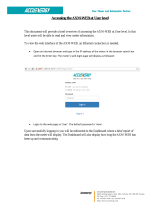
The black/white mini-touch panels contain a black/white 320 x 240 (HV) pixel
liquid crystal display (LCD). The mini-touch panels are self-contained enclosures
that use a microprocessor to control a wide range of audiovisual products. With the
mini-touch panel operating system, you can create custom pages with buttons, icons,
sliders, bargraphs, and import logos and drawings. You can also use the TPDOC or
TPDesign custom touch panel design programs AMX offers to enhance your mini-
touch panel designs. Figure 1 shows an AXT-MLC TiltScreen mini-touch panel.
Figure 2 lists the mini-touch panel types and product names described in this
manual.
Black/white LCD mini-touch panel types and
product names
Product names
Panel types Standard Pushbuttons
TiltScreen AXT-MLC AXT-MLC/PB
UniMount AXU-MLC AXU-MLC/PB
Rack mount AXM-MLC AXM-MLC/PB
Wood
enclosure
AXW-MLC AXW-MLC/PB
Figure 1
AXT-MLC TiltScreen mini-
touch panel
Figure 2
Black/white LCD mini-touch
panel types and product names

2 Introduction Black/White LCD Mini-Touch Panels
What's New
To highlight the new information, features, and operations added since the previous
release of this manual, there are vertical margin bars adjacent to the new
information. New products and features include:
• AXT-MLC (/PB) TiltScreen LCD mini-touch panel installation, wiring, and
specifications
• AXCESS program controls for 2-way wireless communication between the
AXR-WAVES WAVE Server, and the AXT-MLC mini-touch panel equipped
with a WAV-PKM Mini-WavePack wireless power pack
• AXCESS program control for 1-way wireless communication between any
AMX RF and high-/low-frequency IR device, and the AXT-MLC mini-touch
panel equipped with a SMT-PKM Mini-SmartPack wireless power pack
Features
The mini-touch panel offers the following features:
• 2.9 inch x 3.9 inch (HW) LCD
• 320 x 240 (HV) pixel black/white LCD
• Up to 12 external pushbuttons, 6 on either side of display
• Microsoft or Logitech mouse compatible (UniMount and rack-mount models)
• Panel programming, screens, and drawings that can be uploaded and
downloaded with TPDOC (MS-DOS) or TPDesign (Windows) touch panel
design programs.
• Internal RS-232 ports for mouse and/or RS-232 communication (UniMount
and rack-mount panels only)

Black/White LCD Mini-Touch Panels Introduction 3
Applications
The mini-touch panels can control a wide variety of equipment connected to the
AXCESS CardFrame, the internal RS-232 port (UniMount and rack-mount panels
only), or a combination of both. Figure 3 shows a sample AXU-MLC mini-touch
panel and AXCESS Control System configuration.
AXU-MLC/PB
Mouse (optional)
or internal RS-232
port
AXlink cable
AXCESS CardFrame
Television VCR Lighting Camera
The AXT-MLC (/PB) and AXW-MLC (/PB) mini-touch panels use a 4-pin (male)
mini-XLR connector for power and data, and the AXU-MLC (/PB) and AXM-MLC
(/PB) mini-touch panels use a 4-pin AXlink connector for power and data. The mini-
touch panels connect to an AXCESS Control System, AXCENT
2
Integrated AXCESS
Control System, or the AXB-EM232 Enhanced Master/RS-232 Controller. You can
also connect an optional Microsoft or Logitech serial mouse to the RS-232 4-pin
header inside the AXU-MLC (/PB) and AXM-MLC (/PB) to design touch panel
pages and perform touch panel operations.
Figure 3
Sample AXU-MLC/PB mini-
touch panel and AXCESS
Control System
Note
The mouse can be used to
design mini-touch panel pages
and then removed prior to
installation.

4 Introduction Black/White LCD Mini-Touch Panels
What's in this Manual
This manual provides basic instructions on how to use the mini-touch panel
operating system, and installation, basic elements, basic page designs, reference
information, AXCESS programming, battery replacement procedures, 128K memory
upgrades, specifications, technical support information. If you are not familiar with
the AMX touch panel operating system, read through the Mini-Touch Panel Basics
section and create touch panel pages and objects. If you are an experienced AMX
touch panel page designer, read through the Mini-Touch Panel Program Reference
section for complete descriptions of all mini-touch panel operations. Section titles
and descriptions contained in this manual include:
• Installing the Mini-Touch Panel Installation, wiring, and cleaning
instructions.
• Mini-Touch Panel Basics Basic elements associated with the mini-touch
panel operating system such as button types, message and editor selection
bars, and keyboards.
• Designing a Mini-Touch Panel Page Step-by-step instructions to create a
mini-touch panel page, button, joy stick, and bargraph.
• Mini-Touch Panel Program Reference Describes all the mini-touch panel
operations.
• AXCESS Programming Lists AXCESS system commands used to integrate
mini-touch panel features such as page flips, and variable test into an AXCESS
Control System.
• Replacing the Lithium Batteries Shows how to replace the lithium
batteries in the mini-touch panel.
• 128K Memory Upgrade Step-by-step instructions to install the optional
128K integrated circuit (IC) in the mini-touch panel.
• Specifications Mini-touch panel dimensions, LCD screen dimensions,
weight, power, memory, enclosure type and color, accessories, and software
programs.
• Technical Support Helpful hints you can use to check panel wiring, correct
a software program problem, and the numbers to call for AMX technical
support.

Black/White LCD Mini-Touch Panels Installing the Mini-Touch Panel 5
Installing the Mini-Touch Panel
Overview
The section describes how to mount, wire, and clean UniMount and rack-mount
mini-touch panels.
Mounting the Mini-Touch Panels
The following describes how to mount the UniMount and rack-mount mini-touch
panels. The TiltScreen mini-touch panel can be mounted on any flat surface.
AXU-MLC (/PB) and low profile back box
Mount the AXU-MLC (/PB) and low profile back box ( Figure 4):
Low profile back box
AXU-MLC bezel
Release slot
Engraved overlay
Figure 4
AXU-MLC and low profile back
box

6 Installing the Mini-Touch Panel Black/White LCD Mini-Touch Panels
1. Make a cutout in the surface according to the dimensions shown in Figure 5 for
a low-profile back box.
2. Insert a flat head screwdriver into the release slot on the AXU-MLC (/PB)’s
bezel and remove the engraved overlay.
3. Place the AXU-MLC (/PB) into the cutout and mark the screw insert positions as
shown in Figure 4.
4. Remove the AXU-MLC (/PB) and drill four #6-32 insert holes. Then, place a
threaded insert into each hole.
5. Attach the data and power wiring to the AXU-MLC (/PB). Refer to Wiring the
Mini-Touch Panels for wiring diagrams and pinout descriptions.
Figure 5
AXU-MLC and low profile back
box cutout dimensions

Black/White LCD Mini-Touch Panels Installing the Mini-Touch Panel 7
6. Fasten the AXU-MLC (/PB) and low profile back box to the surface using the
#6-32 machine screws supplied with the enclosure.
7. Insert the engraved overlay back into the bezel.
8. Connect the AXlink wiring to the AMX control system, and RS-232 wiring
(optional) to the external RS-232 device. The AXU-MLC (/PB) will beep when
you apply power.
AXU-MLC (/PB) and BB-MTP (solid surfaces)
Mount the AXU-MLC (/PB) and BB-MTP (Figure 6) into a solid surface:
Release slot
Solid surface mounting
flanges
Knockout
BB-MTP UniMount enclosure
AXU-MLC bezel
Engraved overlay
Stud mounting
holes
1. Cut the solid surface according to the cutout dimensions shown in Figure 7.
2. Insert a flat head screwdriver into the release slot on the AXU-MLC (/PB)’s
bezel and remove the engraved overlay.
Note
The mini-touch panel must
always be installed with the
release slot located at the
bottom.
Figure 6
AXU-MLC (/PB) and BB-MTP
UniMount enclosure for solid
surfaces

8 Installing the Mini-Touch Panel Black/White LCD Mini-Touch Panels
RADIUS IN CORNERS
.125 [3.2 MM] MAX
CUTOUT
.187 [4.7 MM] DIA
4 HOLES
TWO .170 [4.3 MM] DIA HOLES PROVIDED ON
ALL SIDES OF BACK BOX FOR STUD MOUNTING.
STUD MOUNTING OPTION:
2.94
1.70
1.70
.125
4.25
[114.3 MM]
7.10
7.46
7.80
[208.0 MM]
.35
.170
.52
3.22
(FRAME)
(FRAME)
[74.7 MM]
[4.3 MM]
[8.9 MM] [180.3 MM]
[189.5 MM]
[198.1 MM]
8.187
[43.2 MM]
[43.2 MM]
[108.0 MM]
4.50
[13.2 MM]
[81.8 MM]
[3.2 MM]
3. Lay the AXU-MLC (/PB) facedown onto a soft cloth and remove the four screws
from the low profile back box. Remove the back box and discard.
4. Place the BB-MTP into the cutout and mark the threaded insert positions as
shown in Figure 7.
5. Remove the BB-MTP and drill eight holes as shown in Figure 6. Then, place #6-
32 threaded inserts into the four holes marked ‘B’ in the cutout dimensions
illustration.
6. Disconnect the AXlink connector from the AMX control system that supplies
power and data to the AXU-MLC (/PB). Then, disconnect the optional RS-232
connector from the external RS-232 device connected to the AXU-MLC (/PB).
7. Remove one or more knockouts to accommodate the wiring as required.
Figure 7
AXU-MLC (/PB) and BB-MTP
cutout dimensions
Note
The BB-MTP can also be
mounted to wood or metal
studs using the pre-drilled stud
mounting holes.

Black/White LCD Mini-Touch Panels Installing the Mini-Touch Panel 9
8. Thread the incoming AXlink and RS-232 wiring through the BB-MTP knockout.
9. Fasten the BB-MTP to the solid surface with the mounting screws supplied with
the enclosure.
10. Connect the AXlink and RS-232 wiring to the AXU-MLC (/PB) circuit card.
Refer to Wiring the Mini-Touch Panel for complete wiring information.
11. Fasten the AXU-MLC (/PB) to the BB-MTP with the #6-32 screws provided with
the enclosure.
12. Insert the engraved overlay back into the bezel.
13. Connect the AXlink wiring to the AMX control system and RS-232 wiring to the
external RS-232 device. The AXU-MLC (/PB) will beep when you apply power.
AXU-MLC (/PB) and BB-MTP (plasterboard)
Mount the AXU-MLC (/PB) and BB-MTP (Figure 8) into a plasterboard surface (or
equivalent):
Release slot
Plasterboard surface
mounting flanges
Knockout
BB-MTP UniMount enclosure
Expansion clips
Engraved overlay
Stud mounting
holes
AXU-MTP bezel
Note
The mini-touch panel must
always be installed with the
release slot located at the
bottom.
Figure 8
AXU-MLC (/PB) and BB-MTP
for plasterboard

10 Installing the Mini-Touch Panel Black/White LCD Mini-Touch Panels
1. Cut the surface according to the cutout dimensions shown in Figure 9.
2. Insert a flat head screwdriver into the release slot on the AXU-MLC (/PB)’s
bezel and remove the engraved overlay.
3. Lay the AXU-MLC (/PB) facedown onto a soft cloth and remove the four screws
from the low profile back box. Remove the back box and discard.
4. Place the BB-MTP into the cutout and mark the threaded insert positions as
shown in Figure 9.
Figure 9
AXU-MLC (/PB) and BB-MTP
cutout dimensions

Black/White LCD Mini-Touch Panels Installing the Mini-Touch Panel 11
5. Remove the BB-MTP and drill four #6-32 insert holes. Then, place a threaded
insert into each hole.
6. Disconnect the AXlink connector from the AMX control system that supplies
power and data to the AXU-MLC (/PB). Then, disconnect the optional RS-232
connector from the external RS-232 device connected to the AXU-MLC (/PB).
7. Thread the incoming AXlink and RS-232 wiring through the BB-MTP knockout.
8. Fasten the BB-MTP to the plasterboard using the expansion screws supplied
with the enclosure.
9. Connect the AXlink and RS-232 wiring to the AXU-MLC (/PB) circuit card.
Refer to Wiring the Mini-Touch Panels for complete wiring information.
10. Fasten the AXU-MLC (/PB) to the BB-MTP with the #6-32 screws supplied with
the enclosure.
11. Insert the engraved overlay back into the bezel.
12. Connect the AXlink wiring to the AMX control system and RS-232 wiring to the
external RS-232 device. The AXU-MLC (/PB) will beep when you apply power.
AXM-MLC (rack mount)
Mount the AXM-MLC (Figure 10) rack mount into an electronic equipment rack:
1. Thread the incoming AXlink and RS-232 (optional) wiring through the opening
in the equipment rack.
2. Disconnect the AXlink connector from the AMX control system that supplies
power and data to the AXM-MLC. Then, disconnect the optional RS-232
connector from the external RS-232 device connected to the AXU-MLC (/PB).
Note
The mini-touch panel must
always be installed with the
release slot located at the
bottom.
Figure 10
AXM-MLC rack-mount mini-
touch panel

12 Installing the Mini-Touch Panel Black/White LCD Mini-Touch Panels
3. Connect the AXlink and RS-232 wiring to the AXM-MLC circuit card. Refer to
Wiring the Mini-Touch Panel for complete wiring information.
4. Insert the AXM-MLC into the rack. Line up the top left and right screw holes
and start the #6-32 screws. Then, start the bottom left and right screws. Tighten
all the screws after you start all the screws.
5. Connect the AXlink wiring to the AMX control system and RS-232 wiring to the
external RS-232 device. The AXM-MLC will beep when you apply power.
AXW-MLC (/PB) (wood enclosure)
Install the AXW-MLC (/PB) (Figure 11) wood enclosure:
1. Thread the incoming AXlink cable to the AXW-MLC (/PB).
2. Disconnect the AXlink connector from the AMX control system that supplies
power and data to the AXW-MLC (/PB).
3. Connect the mini-XLR connector to the AXW-MLC (/PB). Refer to Wiring the
Mini-Touch Panel for complete wiring information.
4. Connect the AXlink wiring to the AMX control system. The AXW-MLC (/PB)
will beep when you apply power.
Figure 11
AXW-MLC (/PB) wood
enclosure
/