Page is loading ...

Used As Anchor Flange
In One Pour Slab
FINISHED FLOOR
Used As
Flashing Flange
Waterproof Membrane
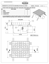
Removable
Flashing Collar
Grate will not tilt out of
drain body when heavy
moving loads pass over it.
BAR-TYPE
GRATE
DEEP SET
TRACTOR GRATE
"SAFE-SET" BUCKET AND GRATE
Bucket Must Be In Place
Before Grate Is Replaced
Additional Perimeter
Drainage Openings
After the top size is determined based on anticipated flow into the drain, the fol-
lowing points should be considered when making the final selection of the floor
drain.
Selection of Top (Based on Anticipated Traffic)–Establish the maximum antici-
pated traffic (loading) which will pass over the grate and select the grate type
which will support that load. Each drain shown in this section has a description
listing the type of load it will take. The categories listed are for various drains in
respect to grate loading. The load classifications are in accordance with the
American National Standards ASME A112.21.1M.
ASME Ratings are as follows:
•
Light Duty
–All grates having safe live load under 2,000 lbs. (900 KG)
•
Medium Duty
–All grates having safe live load between 2,000 lbs. (900 KG)
and 4,999 lbs. (2250 KG)
•
Heavy Duty
–All grates having safe live load between 5,000 lbs. (2250 KG) and
7,499 lbs. (3375 KG)
•
Extra Heavy Duty
–All grates having safe live load between 7,500 lbs. (3375
KG) and 10,000 lbs. (4500 KG)
The above categories are given as a guide only. Conditions of use, load concen-
trations, installations, etc., can affect results and service. For unusual applications,
consult the factory.
After the weight loading capacity is established, a suitable drain can be selected.
Illustrated below are various types of grate designs which will be mentioned
throughout the catalog.
Selection of Top Material–
(Unfinished Areas)
–Drains located in heavy traffic
areas should be specified with heavy duty cast iron grates. In areas where shock
loads are anticipated, a ductile iron grate should be specified in lieu of the cast
iron grate. Cast iron is acceptable for most unfinished areas such as warehouses,
loading docks, boiler rooms and similar areas.
(Finished Areas)
–Most drains are available with nickel bronze or bronze tops to
match the surrounding trim in finished areas. Usually finished areas require light
duty or medium duty tops.
(Finished Areas with Increased Load)
–Many finished floor areas are subject to
increased loadings. Examples are convention centers, equipment showrooms and
industrial plants. Heavy duty cast iron tractor grates can be specified with bronze
or nickel bronze veneered tops. (Specify Fig. No. 2120, 2140, 2250, etc.)
Top Shape–Round, square or rectangular styles are available to blend with all
types of construction and floor patterns. The round top is the most flexible type
since it can be easily oriented to most floor patterns.
Body Selection–Body depth is proportioned to the top size. Many Smith floor
drains can be specified with various body depths. The deeper body is desirable
when unusually large amounts of water are to be drained or an extra large sedi-
ment bucket is required.
Floor drains are primarily used for inside locations where the flow rate
into the drain can be anticipated and for outside areas where rainfall
intensity dictates sizing. Drains should be selected with sufficient top size
and grate free area to pass the anticipated flow. Grate free area is
defined as "the total area of the drainage openings in the grate." The
drain outlet should be sized large enough so that it will safely pass the
maximum flow through the grate, without creating water buildup.
Sizing and Location–For most indoor locations, the grate free area
should be 1 1/2 times the transverse area of the connecting pipe. The
number and location of drains are based on the configuration of the floor
plan, type of operation and location of equipment. Location and number
of floor drains required can be determined only after careful review of the
plans and anticipated building use.
Floor drains or area drains, when used to drain exterior areas, should
have an open area equal to twice the transverse area of the connecting
pipe (Table 1.) See roof drain section for rainfall and sizing data
(Pg. 1-03).
Recommended Grate Free Areas for Various
Outlet Pipe Sizes
1 1/2 2.04 3.06 4.08
2 3.14 4.71 6.28
3 7.06 10.59 14.12
4 12.60 18.90 25.20
5 19.60 29.40 39.20
6 28.30 42.45 56.60
8 50.25 75.38 100.50
Minimum Maximum
Nominal Transverse Flow Requirements Flow Requirements
Pipe Size, Area of Pipe, (Interior Areas) (Exterior Areas)
IN SQ IN SQ IN SQ IN
Table 1
Most floor drain bodies are available with a flange for either anchoring the drain in
the floor slab or for use as a flashing flange in upper floors and waterproofed
areas. Many Smith drains are regularly furnished with a flanged body and a com-
bination "top flashing collar" which can be used to clamp the waterproof mem-
brane.
CUSTOMER
DRIVEN
SMITH
®

The Prefix DX designates a wide flange that can be furnished on certain Smith floor
drains. This flange receives the membranes and coatings of a waterproof floor cov-
ering system. These coverings are thin coatings which are installed in a series of
trowel coats. The covering forms its own membrane, flashing and durable traffic
surface. The wide flange is regularly furnished 4" wide. The usual covering is
approximately 3/16" thick and may be applied over many subsurfaces such as con-
crete, gypsum or wood decks. This type of covering is particularly adaptable to flat
roofs which are used for recreational purposes, balconies, area ways, plazas, sun
decks, floors and corridors.
When a DX flange is required on drains other than those shown in this section, the
prefix DX must be used with the figure number. The flange will be 4" wide (mini-
mum) with a 3/16" lip regularly furnished. If the waterproof deck covering is greater
or less than 3/16", the lip dimension must be specified or the drain has to be set at
the proper elevation by the plumbing contractor to compensate for these differ-
ences. Roughing dimensions of the body must be adjusted accordingly. Drain body
should be set low enough to permit "dimpling" of the area surrounding the drain.
Some job applications require drains with buckets to intercept and collect debris
such as solid objects and leaves so the waste system is protected. Smith engineers
have designed various types of buckets for different applications to accomplish this
purpose. NOTE:Where a bucket is not available, a dome bottom strainer or flat
bottom strainer may be used to protect the waste system.
This bucket is ideal for drains which are located in areas
where a large amount of debris is anticipated. It is partic-
ularly useful in areas such as vegetable storerooms
where vegetables are pre-cleaned and a considerable
amount of leaves and stalks are washed into the drain.
The solid bottom of this bucket retains this type of solid
matter while the overflow is discharged through the
screens in the top of the bucket.
Used where large leafy objects such as peelings, leaves
and paper are to be intercepted. When wetted down,
these types of solids will compact at the bottom of the
bucket. Slots run completely up the sides of the bucket to
offer complete drainage even when the bottom section is
filled with debris.
Used where heavy materials such as sand, stones and
chips are to be intercepted and separated from the
drainage water. When sand laden drainage water enters
the bucket, the sand falls to the bottom and the clear
water flows over the top of the bucket into the waste line.
Jay R. Smith Speedi-Seal (Fig. 9502) and Speedi-Set (L) gaskets are available for
use with cast iron, plastic, steel or glass pipe. Installation of your floor drains using
Speedi-Seal or Speedi-Set can represent a significant reduction in time and labor
costs over conventional caulk or NO-HUB installations.
The caulk support strap eliminates the need to search for supports for the drain dur-
ing the caulking operation and the need to purchase expensive riser clamps. Its
unique design allows it to be used on 2, 3 or 4" service weight or extra heavy pipe.
The installer secures the strap in place, lubricates the plain end of the spigot, then
rests the inside caulk outlet drain on the caulk support strap. The strap supports the
drain body weight and the force created by the caulking operation without slipping.
The inside surface of the Speedi-Seal gasket is then lubricated, pressed in place
down over the pipe and lightly tapped until flush with the top of the pipe. Installation
is fast and simple and the caulk support strap may be left in place or reused.
Speedi-Set drains are available with most bottom outlet models by specifying (L) and
piping material used. Service weight (SW) is regularly furnished or specify extra heavy
(LXH). The Speedi-Set joint consists of a NO-HUB outlet body and a factory inserted
extra heavy or service weight Speedi-Set neoprene gasket. The installer simply lubri-
cates the plain end of the spigot and the inside of the gasket, then presses the
drain
body down over the pipe until contact is made with the internal stop of the gasket. The
installation eliminates the need for hot lead, caulking irons, NO-HUB clamps, etc.
Variations to meet particular job requirements are available. The illustrations shown below are some of the more common variations.
Suffix -B
Sediment Bucket
Suffix -D
Dome Grate
Suffix -H
Hinged Grate
Allows quick access to the
line and assures replacement
of grate.
Suffix -P
Trap Primer Connection
-P050 (1/2") Regularly
Furnished, -P075 (3/4")
available on request.
Suffix -S
Square Top
Suffix -U
Vandal Proof Screws
Flat Head Socket Machine
Screw.
PIPE OD TOLERANCE RANGE GASKET-PIPE COMPATIBILITY
NOM. INCHES MILLIMETERS CAST IRON
JAY R. PIPE PIPE
PVC
SMITH SIZE & FROM TO FROM TO NO-
THIN
COPPER
FIG. NO DESCR. MIN MAX MIN MAXXH SW HUBABS PVC WALLSTEEL DWV GLASS
SW = SERVICE WEIGHT XH = EXTRA HEAVY
L = SPEEDI-SET SERVICE WEIGHT LXH = SPEEDI-SET EXTRA HEAVY SP = STEEL PIPE
SPEEDI-SET SPEEDI-SEAL
9502SW02
2.125 2.390 54.0 60.7 X X X X
9502SW03
3.125 3.390 79.4 86.1 X X X X
9502SW04
4.124 4.390 104.8 111.5 X X X X
9502SW05
5.210 5.390 132.3 136.9 X X
9502SW06
6.210 6.390 157.7 162.3 X X
9502XH02
2.290 2.470 58.2 62.7 X X X X X X
9502XH03
3.410 3.590 86.6 91.2 X X X X X
9502XH04
4.4104.590 112.0116.6 X X X X X
9502XH05
5.410 5.590 137.4142.0 X
9502XH06
6.410 6.590 162.8167.4 X
9502SP06
6.550 6.70 166.4170.2 X X X X
9503L02
2.1252.390 54.0 60.7 X X X
9503L03
3.1253.390 79.4 86.1 X X X X
9503L04
4.1254.390104.8111.5 X X
9503LXH02
2.2902.470 58.2 62.7 X X X X X X
9503LXH03
3.4103.590 86.6 91.2 X X X X X
9503LXH04 4.4104.59112.0116.0 X X X X X
CUSTOMER
DRIVEN
SMITH
®

Adjustable Top–The Smith 2005/2010 Series of floor drains are available with over
100 different strainer heads. Strainer heads have a 3 3/4 - 12 threaded shank which
threads into flashing collar. This type of drain is particularly adaptable to two-pour
construction, such as toilet rooms, shower rooms, locker rooms and other light duty
finished areas. Strainer head is easily adjusted when tile floor is being set.
Reversible flashing collar in low position permits adjustment of the strainer to as
low as 3/4" (measured from top of body pan to finished floor). This low position is
particularly adaptable for installations where ceramic tile is applied directly to the
slab. With collar in high position, sufficient adjustment is available for all normal
two-pour installations. Usually the normal sand and cement fill and ceramic tile
measures approximately 1 1/2". For unusually deep floor fills or unique construc-
tion, additional height can be obtained by using a Suffix -X Extension Adaptor.
NOTE: See below for Suffix -X Extension Adaptor.
Adjustable Top and Extension–Smith has available adjustable drains in the 8 1/2"
and the 12" top sizes. Both sizes are available with light duty, medium duty, or
heavy duty tops. See Table 2 below for variations
Adjustable drains are particularly useful in areas where the finished floor elevation
may vary or is not immediately determined. Additional adjustable extension sleeve
is available for extra deep roughing conditions (Specify Suffix -E).
COLLAR IN
LOW POSITION
COLLAR IN HIGH POSITION
Fig. 2005
NO-HUB Clamp
.
.
.
.
.
.
.
.
.
.
.
.
.
.
..
.
.
.
.
.
.
.
.
.
.
.
.
.
.
.
.
.
.
.
.
.
.
.
.
.
.
.
.
.
.
.
.
.
.
.
.
.
.
.
.
.
Suffix-E
Extension
EXTRA
DEEP
FILL
SECOND
POUR
.
.
.
.
.
.
.
.
.
.
.
.
.
.
.
.
.
.
.
.
.
.
.
.
.
.
.
.
.
.
.
.
.
.
.
.
.
.
.
.
.
.
.
.
.
.
.
.
.
.
.
.
.
.
SLAB
A
C
B
TYPE TOP SIZE TOP FIG. NO. MIN MAX MIN MAX
8 1/2 DIA 2350 2355 1 1/4 2 3/4 3 5/8 5 1/4 2
12 DIA 2360 2365 1 3/4 3 2 3/4 4 3/4 2 1/2
8 1/2 DIA 2310 2315 1 1/4 2 3/4 3 5/8 5 1/4 2
8 1/2 DIA 2320 2325 1 1/4 2 3/4 3 5/8 5 1/4 2
12 DIA 2330 2335 1 3/4 3 2 3/4 4 3/4 2 1/2
12 DIA 2340 2345 1 3/4 3 2 3/4 4 3/4 2 1/4
HEAVY DUTY
MEDIUM DUTY
"SAFE-SET"
ABC
Table 2
REVERSIBLE FLASHING COLLAR
designed to receive all variations of
SMITH strainer heads. Permits vertical
adjustment for strainer and provides posi-
tive clamp of waterproofing membrane
TURN-STYLE SLOTS
permits easy assembly of collar with-
out removal of non-corrosive bolts
AUXILIARY INLET PAD
tapped for trap primer
connection when specified
CAULK OUTLET
regularly furnished, NO-HUB,
Speedi-Set or Threaded Outlets
when specified
SEEPAGE OPENINGS
permit seepage into drain
body
2 PIECE BODY
design eliminates need for
separate flashing device
Cast Bronze XCB
Galvanized Cast Iron XG
Used when a strainer head must be raised to accommodate
deeper floor fill.
NOTE: Extensions can be stacked for
increased maximum adjustment.
SUFFIX -X
2300 SERIES SUFFIX -E
ADJUSTABLE EXTENSIONS
Table 2 lists the min.-max.
adjustment and drains for which
this extension is available.
CUSTOMER
DRIVEN
SMITH
®
/