Moxa NPORT 5110-T User manual

Category
Serial servers
Type
User manual
NPort 5100 Series User’s Manual
Fifth Edition, February 2012
www.moxa.com/product
© 2012 Moxa Inc. All rights reserved.
NPort 5100 Series User’s Manual
The software described in this manual is furnished under a license agreement and may be used only in accordance with
the terms of that agreement.
Copyright Notice
© 2012 Moxa Inc. All rights reserved.
Trademarks
The MOXA logo is a registered trademark of Moxa Inc.
All other trademarks or registered marks in this manual belong to their respective manufacturers.
Disclaimer
Information in this document is subject to change without notice and does not represent a commitment on the part of
Moxa.
Moxa provides this document as is, without warranty of any kind, either expressed or implied, including, but not limited
to, its particular purpose. Moxa reserves the right to make improvements and/or changes to this manual, or to the
products and/or the programs described in this manual, at any time.
Information provided in this manual is intended to be accurate and reliable. However, Moxa assumes no responsibility for
its use, or for any infringements on the rights of third parties that may result from its use.
This product might include unintentional technical or typographical errors. Changes are periodically made to the
information herein to correct such errors, and these changes are incorporated into new editions of the publication.
Technical Support Contact Information
www.moxa.com/support
Moxa
Americas
Toll
-free: 1-888-669-2872
Tel:
+1-714-528-6777
Fax:
+1-714-528-6778
Moxa China (Shanghai office)
Toll
-free: 800-820-5036
Tel:
+86-21-5258-9955
Fax:
+86-21-5258-5505
Moxa Europe
Tel:
+49-89-3 70 03 99-0
Fax:
+49-89-3 70 03 99-99
Moxa As
ia-Pacific
Tel:
+886-2-8919-1230
Fax:
+886-2-8919-1231
Table of Contents
1. Introduction ...................................................................................................................................... 1-1
Overview ........................................................................................................................................... 1-2
Package Checklist ............................................................................................................................... 1-2
Product Features ................................................................................................................................ 1-2
Product Specifications ......................................................................................................................... 1-3
2. Getting Started.................................................................................................................................. 2-1
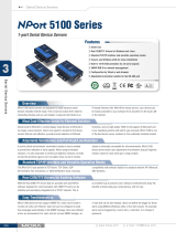
Panel Layout of NPort 5100 Series ........................................................................................................ 2-2
Connecting the Hardware..................................................................................................................... 2-2
Connecting the Power .................................................................................................................. 2-2
Connecting to the Network ........................................................................................................... 2-2
Connecting to a Serial Device ....................................................................................................... 2-3
LED Indicators ............................................................................................................................ 2-3
Adjustable Pull High/Low Resistor for RS-485 Port ........................................................................... 2-3
3. Initial IP Address Configuration ........................................................................................................ 3-1
Initializing the NPort 5100’s IP Address ................................................................................................. 3-2
Factory Default IP Address ................................................................................................................... 3-2
NPort Administration Suite ................................................................................................................... 3-2
ARP................................................................................................................................................... 3-2
Telnet Console ................................................................................................................................... 3-3
Serial Console (19200, n, 8, 1) ............................................................................................................. 3-5
4. Choosing the Proper Operation Mode ................................................................................................ 4-1
Overview ........................................................................................................................................... 4-2
Real COM Mode .................................................................................................................................. 4-2
TCP Server Mode ................................................................................................................................ 4-3
TCP Client Mode ................................................................................................................................. 4-3
UDP Mode .......................................................................................................................................... 4-4
Pair Connection Mode .......................................................................................................................... 4-4
Ethernet Modem Mode ......................................................................................................................... 4-4
Reverse Telnet Mode ........................................................................................................................... 4-5
Disabled Mode .................................................................................................................................... 4-5
5. Web Console Configuration ............................................................................................................... 5-1
Opening Your Browser ......................................................................................................................... 5-2
Basic Settings .................................................................................................................................... 5-3
Network Settings ................................................................................................................................ 5-4
Serial Settings .................................................................................................................................... 5-7
Operating Settings .............................................................................................................................. 5-9
Real COM Mode ........................................................................................................................... 5-9
TCP Server Mode ....................................................................................................................... 5-12
TCP Client Mode ........................................................................................................................ 5-15
UDP Mode ................................................................................................................................ 5-18
Pair Connection Mode ................................................................................................................ 5-20
Ethernet Modem Mode ............................................................................................................... 5-22
Reverse Telnet Mode ................................................................................................................. 5-24
Disabled Mode .......................................................................................................................... 5-25
Accessible IP Settings........................................................................................................................ 5-25
Auto Warning Settings ....................................................................................................................... 5-26
Auto warning: Email and SNMP trap ............................................................................................ 5-26
Event Type ............................................................................................................................... 5-27
Monitor............................................................................................................................................ 5-28
Monitor Line ............................................................................................................................. 5-28
Monitor Async ........................................................................................................................... 5-29
Monitor Async-Settings .............................................................................................................. 5-29
Change Password ............................................................................................................................. 5-29
Load Factory Default ......................................................................................................................... 5-30
6. Configuring NPort Administrator ....................................................................................................... 6-1
Overview ........................................................................................................................................... 6-2
Installing NPort Administrator .............................................................................................................. 6-2
Configuration ..................................................................................................................................... 6-4
Broadcast Search ........................................................................................................................ 6-5
Unlock Password Protection .......................................................................................................... 6-6
Configuring the NPort 5100 .......................................................................................................... 6-8
Upgrading the Firmware ............................................................................................................... 6-9
Export Configuration .................................................................................................................. 6-11
Import Configuration ................................................................................................................. 6-11
Monitor............................................................................................................................................ 6-12
Port Monitor ..................................................................................................................................... 6-17
COM Mapping ................................................................................................................................... 6-17
On-line COM Mapping ................................................................................................................ 6-18
Off-line COM Mapping ................................................................................................................ 6-22
IP Address Report ............................................................................................................................. 6-23
7. NPort CE Driver Manager for Windows CE ......................................................................................... 7-1
Overview ........................................................................................................................................... 7-2
Installing NPort CE Driver Manager ....................................................................................................... 7-2
Using NPort CE Driver Manager ............................................................................................................ 7-2
8. IP Serial LIB ...................................................................................................................................... 8-1
Overview ........................................................................................................................................... 8-2
IP Serial LIB Function Groups ............................................................................................................... 8-2
Example Program ............................................................................................................................... 8-3
A. Pinouts and Cable Wiring .................................................................................................................. A-1
Port Pinout Diagrams .......................................................................................................................... A-2
Ethernet Port Pinouts ................................................................................................................... A-2
NPort 5110 Serial Port Pinouts ...................................................................................................... A-2
NPort 5130 Serial Port Pinouts ...................................................................................................... A-2
NPort 5150 Serial Port Pinouts ...................................................................................................... A-2
Cable Wiring Diagrams ........................................................................................................................ A-3
Ethernet Cables........................................................................................................................... A-3
B. Well Known Port Numbers ................................................................................................................ B-1
C. SNMP Agents with MIB II & RS-232/422/485 Link Groups ............................................................... C-1
D. Auto IP Report Protocol .................................................................................................................... D-1
E. Compliance Notice ............................................................................................................................. E-1
1
1. Introduction
NPort 5100 and NPort 5110-T are advanced, 1-port RS-232/422/485 serial device servers that make it easy to
network-enable serial devices.
The following topics are covered in this chapter:
Overview
Package Checklist
Product Features
Product Specifications
NPort 5100 Series Introduction
1-2
Overview
NPort 5100 series device servers are designed to make your industrial serial devices Internet ready instantly,
and are well-suited for POS security market applications. The compact size of NPort 5100 device servers makes
them the ideal choice for connecting your RS-232/422/485 serial devices, such as card readers and payment
terminals, to an IP-based Ethernet LAN, making it possible for your software to access serial devices located
anywhere on a local LAN, or the Internet.
NPort 5100 supports several operation modes, including TCP Server, TCP Client, UDP Server/Client, Pair
Connection, and Ethernet Modem, ensuring the compatibility of network software that uses a standard network
API (Winsock, BSD Sockets). In addition, NPort’s Real COM/TTY drivers allow you to set up your COM/TTY port
software to work over a TCP/IP network in no time. This excellent feature preserves your software investment
and lets you enjoy the benefits of networking your serial devices instantly.
NPort 5100 device servers support automatic IP configuration protocols (DHCP, BOOTP) and manual
configuration via the handy web browser console. Both methods ensure quick and effective installation. And
with NPort 5100’s Windows Utility, installation is very straightforward, since all system parameters can be
stored and then copied to other device servers simultaneously.
Package Checklist
The NPort 5100 Series products are shipped with the following items:
Standard Accessories
1 NPort 5100 serial device server
Quick Installation Guide
Document & Software CD
Optional Accessories
DK-35A DIN-Rail Mounting Kit (35 mm)
NOTE: Notify your sales representative if any of the above items is missing or damaged.
Product Features
The NPort 5100 have the following features:
Low cost, credit card size
Makes your serial devices Internet ready
Easy wall and DIN-Rail mounting
Real COM/TTY driver for Windows and Linux
Fixed TTY driver for SCO OpenServer, SCO Unixware 7, SCO Unixware 2.1
Versatile socket operation modes: TCP Server, TCP Client, UDP, and Ethernet Modem
Pair Connection mode for connecting two serial devices over a network without a PC
Easy-to-use Windows Utility for mass installation
Auto-detecting 10/100 Mbps Ethernet
Built-in 15 KV ESD protection for all serial signals
Supports SNMP MIB-II for network management
Configuration via web/Telnet/serial console
Configuration utility automatically finds NPort devices on the network
Supports Reverse Telnet mode
Displays uptime on the Overview web page of NPort Configurator
NPort 5100 Series Introduction
1-3
Product Specifications
2
2. Getting Started
This chapter includes information about installing NPort 5100. The following topics are covered:
The following topics are covered in this chapter:
Panel Layout of NPort 5100 Series
Connecting the Hardware
Connecting the Power
Connecting to the Network
Connecting to a Serial Device
LED Indicators
Adjustable Pull High/Low Resistor for RS-485 Port
NPort 5100 Series Getting Started
2-2
Panel Layout of NPort 5100 Series
NOTE: The layouts of NPort 5130 and NPort 5150 are the same as for NPort 5110.
Connecting the Hardware
This section describes how to connect the NPort 5100 to serial devices for first time testing purposes. We cover
Connecting to the Network, Connecting to a Serial Device, and LED Indicators.
Connecting the Power
Connect the 12 to 48 VDC power cord with NPort 5100’s power input. If the power is properly supplied, the
“Ready” LED will show a solid red color until the system is ready, at which time the “Ready” LED will change to
a green color.
Connecting to the Network
Connect one end of the Ethernet cable to NPort 5100’s 10/100M Ethernet port and the other end of the cable
to the Ethernet network. NPort 5100 will indicate a valid connection to the Ethernet in the following ways:
The Ethernet LED maintains a solid green color when connected to a 100 Mbps Ethernet network.
The Ethernet LED maintains a solid orange color when connected to a 10 Mbps Ethernet network.
The Ethernet LED will flash when Ethernet packets are being transmitted or received.
NPort 5100 Series Getting Started
2-3
Connecting to a Serial Device
Connect the serial data cable between NPort 5100 and the serial device. NPort 5100’s serial port uses the
RS-232/422/485 interface to transmit data. The port uses a standard male DB9 pin assignment. Refer to
Appendix A to see the signal definitions for the port.
LED Indicators
NPort 5100 has 3 LED indicators, as described in the following table.
LED Name LED Color LED Function
Ready
Red
Steady on: Power is on and NPort 5100 is booting up.
Blinking: Indicates an IP conflict, or DHCP or BOOTP server did not
respond properly.
Green
Steady on: Power is on and NPort 5100 is functioning normally.
Blinking: The device server has been located by Administrators
Location function.
Off
Power is off, or power error condition exists.
Link
Orange The device is connected to a 10 Mbps Ethernet connection.
Green The device is connected to a 100 Mbps Ethernet connection.
Off Ethernet cable is disconnected, or has a short.
Tx/Rx
Orange Serial port is receiving data.
Green Serial port is transmitting data.
Off No data is being transmitted or received through the serial port.
Adjustable Pull High/Low Resistor for RS-485 Port
In some critical environments, you may need to add termination resistors to prevent the reflection of serial
signals. When using termination resistors, it is important to set the pull high/low resistors correctly so that the
electrical signal is not corrupted. Since a particular pull high/low resistor value cannot fit all environments, the
NPort 5150/5130 uses jumpers to set the pull high/low resistor values for each serial port.
To set a termination resistor to 150 KΩ, make sure that the two jumpers (JP3 and JP4) assigned to the
serial port are not shorted by jumper caps. This is the default setting.
To set a termination resistor to 1 KΩ, make sure that the two jumpers (JP3 and JP4) assigned to the serial
port are shorted by jumper caps.
ATTENTION
Do not use the 1 KΩ setting on the NPort 5150 when using the RS
-232 interface. Doing so will degrade the
RS
-232 signals and shorten the maximum allowed communication distance.
NPort 5100 Series Getting Started
2-4
NPort 5150/5130 Jumpers
3
3. Initial IP Address Configuration
When setting up your NPort 5100 for the first time, you should first configure the IP address. This chapter
introduces the method to configure the device server’s IP address. For more details about network settings, see
the Network Settings section from Chapter 5, Web Console Configuration.
The following topics are covered in this chapter:
Initializing the NPort 5100’s IP Address
Factory Default IP Address
NPort Administration Suite
recommended configuration method
ARP
Telnet Console
Serial Console (19200, n, 8, 1)
NPort 5100 Series Initial IP Address Configuration
3-2
Initializing the NPort 5100’s IP Address
1. Determine whether your NPort 5100 needs to use a Static IP or Dynamic IP (either DHCP or BOOTP
application).
2. If the NPort 5100 is used in a Static IP environment, you can use NPort 5100 Administration Suite,
ARP, Web Console, Telnet Console, or Serial Console to configure the new IP address.
3. If the NPort 5100 is used in a Dynamic IP environment, you can use NPort 5100 Administration suite,
Web Console, Telnet Console, or Serial Console to configure the NPort 5100 to get an IP address
dynamically with DHCP, DHCP/B OOTP, or BOOTP.
ATTENTION
Consult your network administrator
on how to reserve a fixed IP address for your NPort 5100 in the MAC-IP
mapping table when using a DHCP Server or BOOTP Server.
In most appl
ications, you should assign a fixed IP
address to your NPort
5100.
Factory Default IP Address
NPort 5100 products are configured with the following default private IP address:
Default IP address: 192.168.127.254
(IP addresses of the form 192.168.xxx.xxx are referred to as private IP addresses, since it is not possible to
access a device configured with a private IP address directly from a public network. For example, you would not
be able to ping such a device from an outside Internet connection. NPort 5100 applications that require sending
data over a public network, such as the Internet, require setting up the server with a valid public IP address,
which can be leased from a local ISP.)
NPort Administration Suite
NPort Administration Suite consists of useful utility programs that are used to configure and manage your NPort
5100s.
See Chapter 5 for details on how to install NPort Administration Suite, and how to use this suite of
useful utilities to set up IP addresses and configure your NPort 5100 serial device servers.
ARP
You can make use of the ARP (Address Resolution Protocol) command to set up an IP address for your NPort
5100. The ARP command tells your computer to associate the NPort 5100’s MAC address with the intended IP
address. You must then use Telnet to access the NPort 5100, at which point the device servers IP address will
be reconfigured.
ATTENTION
In order to use this setup method, both your computer and the NPort
5100 must be connected to the same
LAN.
Or, you may use a cross-over Ethernet cable to connect the NPort 5100 directly to your computer’s
Ethernet card.
Your NPort 5100 must be configured with the factory default IP address192.168.127.254
before
executing the ARP command, as described below.
NPort 5100 Series Initial IP Address Configuration
3-3
Take the following steps to use ARP to configure the IP address:
1. Obtain a valid IP address for your NPort 5100 from your network administrator.
2. Obtain the NPort 5100s MAC address from the label on its bottom panel.
3. Execute the ‘arp -s’ command from your computer’s MS-DOS prompt by typing:
arp –s 192.168.200.100 00-90-E8-xx-xx-xx
This is where 192.168.200.100 is the new IP address and 00-90-E8-xx-xx-xx is the MAC address for your
NPort 5100 (be sure to use the numbers determined in steps 1 and 2).
4. Next, execute a special Telnet command by typing:
telnet 192.168.200.100 6000
After issuing this command, a Connect failed message will appear, as shown here. After the NPort 5100
reboots, its IP address should be updated to the new address, and you can reconnect using either Telnet,
Web, or Administrator to check that the update was successful.
Telnet Console
Depending on how your computer and network are configured, you may find it convenient to use network
access to set up your NPort 5100’s IP address. This can be done using the Telnet.
1. From the Windows desktop, click Start and then select Run.
2. Type telnet 192.168.127.254 (use the correct IP address if different from the default) in the Open text
input box, and then click OK.
3. When the Telnet window opens, if you are prompted to input the Console password, input the password
and then press Enter. Note that this page will only appear if the NPort 5100 is password protected.
NPort 5100 Series Initial IP Address Configuration
3-4
4. Type 2 to select Network settings, and then press Enter.
5. Type 1 to select IP address and then press Enter.
6. Use the Backspace key to erase the current IP address, type in the new IP address, and then press Enter.
7. Press any key to continue.
NPort 5100 Series Initial IP Address Configuration
3-5
8. Type m and then press Enter to return to the main menu.
9. Type s and then press Enter to Save/Restart the system.
10. Type y and then press Enter to save the new IP address and restart the NPort 5100.
Serial Console (19200, n, 8, 1)
You may use the RS-232/422/485 console port to set up the IP address for NPort 5100. We suggest using
PComm Terminal Emulator, which is available free of charge as part of the PComm Lite program suite (found
on the Software CD that comes with the product), to carry out the installation procedure, although other similar
utilities may also be used.
Before you start to configure the NPort 5100 via serial console, turn off the power and connect the serial cable
from NPort 5100 to your computer’s serial port.
1. Connect NPort 5100’s serial port 1 directly to your computer’s male RS-232/422/485 serial port.
2. From the Windows desktop, click Start
Programs PComm Lite Terminal Emulator.
3. When the PComm Terminal Emulator window opens, first click on the Port Manager menu item and
select Open, or simply click on the Open icon.
NPort 5100 Series Initial IP Address Configuration
3-6
4. The Property window opens automatically. From the Communication Parameter page, select the
appropriate COM port for the connection, COM1 in this example, and 19200 for Baud Rate, 8 for Data
Bits, None for Parity, and 1 for Stop Bits.
5. From the Property window’s Terminal page, select ANSI or VT100 for Terminal Type and then click OK.
If you select Dumb Terminal as the terminal type, some of the console functionsespecially the “Monitor”
functionmay not work properly.
6. Press the “ ` ” key continuously and then power on the NPort 5100.
7. NPort 5100 will receive the “ ` ” string continuously and then auto switch from data mode to console mode.
8. Input the password when prompted. Note that this page will only appear when the NPort 5100 has been set
up for password protection.
NPort 5100 Series Initial IP Address Configuration
3-7
9. Start configuring the IP address under Network Settings. Refer to step 4 in the Telnet Console section
for the rest of the IP settings.
4
4. Choosing the Proper Operation Mode
In this section, we describe the various NPort 5100 operation modes. The options include Real COM Mode,
which uses a driver installed on the host computer, and operation modes that rely on TCP/IP socket
programming concepts. After choosing the proper operation mode in this chapter, refer to Chapter 5 for
detailed configuration parameter definitions.
The following topics are covered in this chapter:
Overview
Real COM Mode
TCP Server Mode
TCP Client Mode
UDP Mode
Pair Connection Mode
Ethernet Modem Mode
Reverse Telnet Mode
Disabled Mode
NPort 5100 Series Choosing the Proper Operation Mode
4-2
Overview
NPort 5100 serial device servers network-enable traditional RS-232/422/485 devices, in which a serial device
server is a tiny computer equipped with a CPU, real-time OS, and TCP/IP protocols that can bi-directionally
translate data between the serial and Ethernet formats. Your computer can access, manage, and configure
remote facilities and equipment over the Internet from anywhere in the world.
Traditional SCADA and data collection systems rely on serial ports (RS-232/422/485) to collect data from
various kinds of instruments. Since NPort 5100 Serial Device Servers network-enable instruments equipped
with an RS-232/422/485 communication port, your SCADA and data collection system will be able to access all
instruments connected to a standard TCP/IP network, regardless of whether the devices are used locally or at
a remote site.
The NPort 5100 is an external IP-based network device that allows you to expand the number of serial ports for
a host computer on demand. As long as your host computer supports the TCP/IP protocol, you won’t be limited
by the host computer’s bus limitation (such as ISA or PCI), or lack of drivers for various operating systems.
In addition to providing socket access, the NPort 5100 also comes with a Real COM/TTY driver that transmits
all serial signals intact. This means that your existing COM/TTY-based software can be preserved, without
needing to invest in additional software.
Three different Socket Modes are available: TCP Server, TCP Client, and UDP Server/Client. The main
difference between the TCP and UDP protocols is that TCP guarantees delivery of data by requiring the recipient
to send an acknowledgement to the sender. UDP does not require this type of verification, making it possible
to offer speedier delivery. UDP also allows data to be unicast to only one IP address, or multicast to groups of
IP addresses.
Real COM Mode
NPort 5100 comes equipped with COM drivers that work
the NPort 5100
Real COM Mode also supports up to 4
ATTENTION
The driver used for Real COM Mode
is bundled with NPort Administrator. The driver is installed on your
computer automatically when you install NPort 5100 Administration Suite.
One of the major conveniences of using Real COM Mode is that Real COM Mode allows users to continue using
RS-232/422/485 serial communications software that was written for pure serial communications applications.
The driver intercepts data sent to the host’s COM port, packs it into a TCP/IP packet, and then redirects it
through the host’s Ethernet card. At the other end of the connection, the NPort 5100 accepts the Ethernet
frame, unpacks the TCP/IP packet, and then sends it transparently sends it to the appropriate serial device
attached to one of the NPort 5100s serial ports.
  • Page 1 1
  • Page 2 2
  • Page 3 3
  • Page 4 4
  • Page 5 5
  • Page 6 6
  • Page 7 7
  • Page 8 8
  • Page 9 9
  • Page 10 10
  • Page 11 11
  • Page 12 12
  • Page 13 13
  • Page 14 14
  • Page 15 15
  • Page 16 16
  • Page 17 17
  • Page 18 18
  • Page 19 19
  • Page 20 20
  • Page 21 21
  • Page 22 22
  • Page 23 23
  • Page 24 24
  • Page 25 25
  • Page 26 26
  • Page 27 27
  • Page 28 28
  • Page 29 29
  • Page 30 30
  • Page 31 31
  • Page 32 32
  • Page 33 33
  • Page 34 34
  • Page 35 35
  • Page 36 36
  • Page 37 37
  • Page 38 38
  • Page 39 39
  • Page 40 40
  • Page 41 41
  • Page 42 42
  • Page 43 43
  • Page 44 44
  • Page 45 45
  • Page 46 46
  • Page 47 47
  • Page 48 48
  • Page 49 49
  • Page 50 50
  • Page 51 51
  • Page 52 52
  • Page 53 53
  • Page 54 54
  • Page 55 55
  • Page 56 56
  • Page 57 57
  • Page 58 58
  • Page 59 59
  • Page 60 60
  • Page 61 61
  • Page 62 62
  • Page 63 63
  • Page 64 64
  • Page 65 65
  • Page 66 66
  • Page 67 67
  • Page 68 68
  • Page 69 69
  • Page 70 70
  • Page 71 71
  • Page 72 72
  • Page 73 73
  • Page 74 74
  • Page 75 75
  • Page 76 76
  • Page 77 77
  • Page 78 78
  • Page 79 79
  • Page 80 80
  • Page 81 81
  • Page 82 82
  • Page 83 83
  • Page 84 84
  • Page 85 85
  • Page 86 86
  • Page 87 87
  • Page 88 88
  • Page 89 89
  • Page 90 90
  • Page 91 91
  • Page 92 92
  • Page 93 93
  • Page 94 94

Moxa NPORT 5110-T User manual

Category
Serial servers
Type
User manual

Ask a question and I''ll find the answer in the document

Finding information in a document is now easier with AI