Page is loading ...

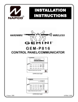
HARDWIRE WIRELESS
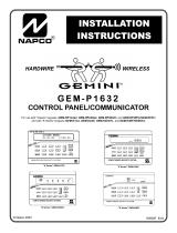
GEM-P3200
CONTROL PANEL/COMMUNICATOR
Programming the GEM-P3200 Control Panel with the
"Classic" GEM-RP2ASe2, GEM-RP3DGTL, and GEM-RP4RFC/GEM-RP4C Keypads and
the "K Series" GEM-K2AS, GEM-K3DGTL, and GEM-K4RF/GEM-K4 Keypads
WI1184B 2/06
© NAPCO 2006
R
Publicly traded on NASDAQ Symbol: NSSC
Quick Start (for GEM-K3DGTL):
1. Refer to the wiring diagram, connect Siren, Aux. Power, PGM
Output, Remote Bus, Earth Ground, Zone and Telephone
Wiring. NOTE: See Installation Instructions (WI817).
2. Connect AC power first and then the battery.
3. Configure the keypad (see page 65).
4. Access the Easy Menu Driven (Dealer Program) Mode:
Press:
EEEEEER
Press NO until “17” appears on the keypad display.
Press NEXT/YES to enter Dealer Program Mode. See page 5.
Master Security Code
(on microshield)
Quick Start (for GEM-K2ASe2):
1. Refer to the wiring diagram, connect Siren, Aux. Power, PGM
Output, Remote Bus, Earth Ground, Zone and Telephone
Wiring. NOTE: See Installation Instructions (WI817).
2. Connect AC power first and then the battery.
3. Configure the keypad (see page 65).
4. Access the Easy Menu Driven (Dealer Program) Mode:
Press:
EEEEEER
Press NO until “TURNON PROG Y/N” appears on the keypad display.
Press NEXT/YES to enter Dealer Program Mode. See page 5
Master Security Code
(on microshield)
PROGRAMMING
INSTRUCTIONS
"K Series" GEM-K2AS "K Series" GEM-K3DGTL
32
"K Series" GEM-K4RF/GEM-K4
32

THIS MANUAL INCLUDES FEATURES WHICH ARE ONLY AVAILABLE IN CONTROL PANEL FIRMWARE
VERSION 50 OR LATER.
IMPORTANT NOTE
This manual supports the keypad programming of the GEM-P3200 control panel with the NAPCO "classic" GEM-
RP2ASe2, GEM-RP3DGTL and GEM-RP4RFC/GEM-RP4C keypads as well as the GEM-K2AS, GEM-K3DGTL and
GEM-K4RF/GEM-K4 "K Series" keypads. The new "K Series" models offer the new STAY and AWAY buttons with sim-
plified functionality, along with the new MENU and ENTER buttons. While the instructions in this manual are depicted
using the "K Series" keypads, the manual applies to both the "classic" and the "K Series" keypads.
Program Mode is the same for both keypads--only the button names have changed, as follows:
•The A button and the R button operate identically (in Program Mode) for both keypads.
•The D button and the U button operate identically (in Program Mode) for both keypads.
•The button and the button operate identically (in Program Mode) for both keypads. The words
"NEXT/YES button" are used in this manual.
•The button and the button operate identically (in Program Mode) for both keypads. The words
"PRIOR/NO button" are used in this manual.
For consistency, it is recommended that all keypads either be all "classic" or all "K Series"--both keypad
types should not be used in one alarm system.
NAPCO Security Systems, Inc.
333 Bayview Avenue, Amityville, New York 11701
For Sales and Repairs, call toll free: (800) 645-9445
For direct line to Technical Service,
call toll free: (800) 645-9440
Internet: http://www.napcosecurity.com
CHANGES FROM PREVIOUS EDITION
The following changes have been made to this manual (WI1184B) since the previous edition (WI1184A).
New addresses added to accommodate the GEM-ACM1D / GEM-2D Access Control Accessories, as follows:
•ACM Zone Options (Address 2740-2779)
•ACM Global Flags (Address 2780)
•ACM Timeouts (Address 2782-2783)
•ACM Door Area Options (Address 2784-2791)
•ACM Scheduled Free Access (Address 4072-4079)
•System Options (Address 2423)
•Emergency Free Access (Address 4080)
•Keypad Home Area / ACM Door #1 Area (Hex) (Address 2425-2439)
•Addition to the Easy Program Menu instructions, "Enter Proximity Card Users".
Existing addresses were changed and new addresses were added to accommodate the NAPCO NetLink™ NL-Mod device, as follows:
•(Address 0526, 0551 & 0576) For each telephone number desired, enable "Report to TCP/IP Receiver or AES" for Telco 1, Telco 2 and Telco 3.
•(Address 1022) Enable "Callback Telephone No. Select". Enter either "1" for Callback Telephone Number 1 or "2" for Callback Telephone Number 2.
•(Address 1027) Enable "Handshake for Local Telemetry".
•(Address 2423) Enable "TCP/IP Communications".
•(Address 2423) Enable "TCP/IP Panel/Site Initiated Functions".

L NAPCO Security Systems X GEM-P3200 Programming Instructions
Page 3
WI1184B 2/06
TABLE OF CONTENTS
Refer to accompanying GEM-P3200 Installation Instructions (WI817) for installation information.
IMPORTANT NOTE ......................................................................................2
CHANGES FROM PREVIOUS EDITION ....................................................2
SYSTEM PROGRAMMING OPTIONS .......................................................4
Introduction ..............................................................................................4
Downloading From a Computer .............................................................4
EASY MENU DRIVEN PROGRAM MODE ................................................5
Dealer Program - Preliminary Information .............................................5
Accessing Dealer Program Mode ..........................................................5
Customizing a Default Program .............................................................5
GEM-RP2ASe2/GEM-K2AS KEYPAD Easy Program Menu ......6
GEM-RP3DGTL/GEM-K3DGTL and GEM-RP4RFC/
GEM-K4RF KEYPAD Easy Program Menu ............................15
DIRECT ADDRESS PROGRAM MODE ...................................................24
Keypad Programming Overview ..........................................................24
Accessing Direct Address Program Mode ..........................................24
Keypad Address Program Mode Display ............................................25
Direct Address Program Mode Keypad Commands ..........................25
Conventions Used in this Manual ........................................................27
PROGRAMMING OPTIONS & WORKSHEETS .....................................28
SYSTEM DELAYS & TIMEOUTS (ADDRESS 0000-0002, 2402,
2406, 2414 & 3902) ....................................................................28
SYSTEM DELAYS & TIMEOUTS (ADDRESS 2407, 2408 & 4088) .28
SYSTEM DELAYS & TIMEOUTS (ADDRESS 2400, 2401, 2403-
2405, 4082 & 4083) ....................................................................29
KEYPAD SYSTEM CODES (ADDRESS 0490, 0495 & 0500) ..........29
CS RECEIVER FORMAT OPTIONS (ADDRESS 0520, 0521, 0525,
0526, 0550, 0551, 0575 & 0576) ...............................................30
CS RECEIVER TELEPHONE NUMBERS (ADDRESS 0527-0546,
0552-0571, 0577-0596) .............................................................31
DOWNLOAD/CALLBACK OPTIONS (ADDRESS 4089, 0600-0619,
0625-0647, 1022 & 1023) ..........................................................31
CS SUBSCRIBER ID NUMBERS (ADDRESS 0650-0787) ..............32
CS SUBSCRIBER ID NUMBERS (ADDRESS 0790-0857) ..............33
CS REPORTING CODES (ADDRESS 0859-0883) ...........................33
CS REPORTING CODES (ADDRESS 0870-0904) ...........................34
CS AREA & SYSTEM REPORTING OPTIONS (ADDRESS 1024-
1027) ...........................................................................................34
CS ZONE REPORTING CODES (ADDRESS 0910-0957) ...............35
CS USER REPORTING CODES (ADDRESS 1030-1048) ...............36
CS USER REPORTING CODES (ADDRESS 1056-1074) ...............37
GLOBAL SYSTEM TROUBLE REPORTING OPTIONS
(ADDRESS 1082-1116) ............................................................38
AREA SYSTEM TROUBLE REPORTING OPTIONS (ADDRESS
1120-1137) ................................................................................. 39
ZONE OPTIONS / ZONES 1-16 (ADDRESS 1200-1386) .................40
ZONE OPTIONS / ZONES 17-32 (ADDRESS 1402-1586) ..............41
ZONE OPTIONS / ZONES 33-48 (ADDRESS 1602-1786) ..............42
ZONE OPTIONS / ZONES 1-48 (ADDRESS 1200-1786) .................43
SYSTEM OPTIONS (ADDRESS 2415-2419) ....................................44
SYSTEM OPTIONS (ADDRESS 2420-2422, 3874) ..........................45
ALARM/TROUBLE REPORTING CODES (ADDRESS 3879-3881) 46
SYSTEM OPTIONS (ADDRESS 3882-3901, 3903-3905 & 4084) ...46
KEYPAD OPTIONS (ADDRESS 2425-2446) .....................................47
KEYPAD OPTIONS (ADDRESS 2425-2446) .....................................48
ACM GLOBAL FLAGS (ADDRESS 2780) .......................................... 48
ACM TIMEOUTS (ADDRESS 2782-2783) .........................................48
ACM DOOR AREA OPTIONS (ADDRESS 2784-2787) ................... 49
ACM SCHEDULED FREE ACCESS (ADDRESS 4072-4075) ......... 49
KEYPAD HOME AREA / ACM DOOR #1 AREA (HEX) (ADDRESS
2425-2431) ................................................................................. 50
SYSTEM OPTIONS (ADDRESS 2423) ..............................................51
EMERGENCY FREE ACCESS (ADDRESS 4080) ...........................51
USER AREA OPTIONS (ADDRESS 2455-2502) ..............................52
EZM GROUP OPTIONS (ADDRESS 2600-2621) .............................53
AREA ARMING OPTIONS (ADDRESS 2650-2651) ......................... 54
REMOTE ACCESS LOGGING (ADDRESS 3184) ............................ 54
AREA OUTPUT CONTROL OPTIONS (ADDRESS 2700-2733) .....55
RF RECEIVERS & SUPERVISORY TIMER OPTIONS (ADDRESS
3776 & 3760-3775) ....................................................................56
EXTERNAL RELAY CONTROL / RELAYS 1-24 (ADDRESS 3778-
3801 & 2800-2895) ....................................................................57
NUMBER OF RELAY BOARD MODULES (ADDRESS 3777) ........61
SYSTEM RESET OPTIONS (ADDRESS 4091-4093) ......................62
USER PROGRAM MODE .......................................................................... 63
Preliminary Information ......................................................................... 63
Accessing User Program Mode ........................................................... 63
User Codes ...........................................................................................64
KEYPAD CONFIGURATION MODE ........................................................65
Configuring the Keypads ...................................................................... 65
ALPHABETICAL INDEX ............................................................................66
ADDRESS NUMBER LOCATION INDEX ................................................71
GEM-P3200 WIRING DIAGRAM ..............................................................76

X GEM-P3200 Programming Instructions L NAPCO Security Systems
Page 4 WI1184B 2/06
SYSTEM PROGRAMMING OPTIONS
INTRODUCTION
The GEM-P3200 control panel may be programmed by various means, each of which will be covered in detail in the sections
that follow. Keypad displays shown are for a GEM-K2AS, the GEM-K3DGTL, and the GEM-K4/GEM-K4RF series. With the
GEM-RP2ASe2/GEM-K2AS keypads, because of their reduced display capabilities, messages are abbreviated and will scroll
through two or more screens. Zone descriptions cannot be programmed using GEM-K2AS/GEM-RP2ASe2, GEM-K3DGTL/
GEM-RP3DGTL, nor a GEM-K4RF/RP4RFC series keypad, therefore a GEM-RP1CAe2 or GEM-K1CA keypad must be
used.
Downloading From a Computer. This is the preferred method of programming. The panel may be downloaded from
(or uploaded to) an IBM PC-compatible computer, either locally or remotely. Napco's PCD-Windows Quickloader
software features context-sensitive help screens as well as an error-checking utility that prevents programming of
incompatible or conflicting data to ensure proper panel operation. Note: Unattended downloading from a computer is
not allowed for Fire Alarm or UL installations.
Easy Menu-Driven Program (Dealer Program) Mode - Keypad Programming. The Easy Menu-Driven Program
Mode allows keypad programming of number of zones in area 1 and 2, panel zone doubling, number of fire zones
(both 4-wire and 2-wire), local or Central Station reporting, number of exit/entry zones, number of interior zones, num-
ber of 24 hour zones, number of chime zones, Chime 2 zones, Exit/Entry2 zones, 50ms loop response zones (Note:
750mS is required for Loop Response time in UL installations), aux output activated on alarm zones, sensor watch
zones, keypad sounder on alarm zones, auto bypass re-entry zones, EOLR zones, number of keypads in area 1 and
2, Central Station telephone number, Central Station account number, Central Station receiver format, User Codes, RF
transmitter points, RF keyfob transmitters, zone descriptions, dealer code, Telco line fault test, Burg output chirp on
keyfob, enable CP-01, and clear dealer program/cold start. For new panels, a custom default program may be created
at the keypad. A menu-driven utility prompts the installer to configure the system. Further detailed customization is
accomplished in the Direct Address Program Mode.
Direct Address (Dealer Program) Program Mode - Keypad Programming. The Direct Address Program Mode is
an extension of the Dealer Program Mode wherein data is entered at the keypad by specific location. This mode is
accessed from the Easy Menu Driven Program Mode by pressing the C button at any time.
User Program Mode - Keypad programming. The User Program Mode is intended for authorized users and is
limited to keypad programming of User Codes, Time, Date and Zone Descriptions.
DOWNLOADING FROM A COMPUTER
The control-panel program may be downloaded from the computer by any of the following methods.
Local Downloading
(Note: This procedure should be used after installation, after peripheral devices are connected).
For direct high-speed data transfer to the control panel from a desktop computer, connect the download jack (JP2) on
the panel to the LOCAL jack (J3) on the Napco PCI2000/3000 computer interface using the supplied 6-conductor
cable. (Refer to PCI2000/3000 Installation Instructions WI443 for wiring diagram and procedures).
Similarly, a high-speed local download may be made in the field using a notebook or laptop computer. Connect JP2
on the control panel to a Napco PCI-MINI computer interface using the 6-conductor cable supplied. (Refer to PCI-MINI
Installation Instructions WI767).
Remote Downloading
(Also see PCI2000/3000 Installation Instructions WI443).
Function Mode.
Start by establishing a telco connection between the computer operator and the installer. During this procedure, voice
contact will be lost, therefore both the installer and the computer operator should be familiar with the operation. When
a steady high-pitched tone is heard at the site phone, access the “ACTIVATE DOWNLOAD” Function (see Keypad
Programming Modes), then press the U button or the YES button; the site phone will go dead. Hang up the phone
and wait for a call from the central station confirming a successful download.
Callback Method.
An installed, unattended panel may be programmed or reprogrammed remotely using the Callback-Method Download
feature of the PCD Windows software. Remote downloading requires a modem compatible with the PCI2000/3000.
Upon answering the call from the computer, the panel will verify the Download Security Code and, if confirmed, will
establish a connection. If a Callback Number is programmed into the panel, the panel will automatically disconnect
and call the computer at this number before establishing a connection.
SYSTEM PROGRAMMING OPTIONS

L NAPCO Security Systems X GEM-P3200 Programming Instructions
Page 5
WI1184B 2/06
EASY MENU DRIVEN PROGRAM MODE
DEALER PROGRAM - PRELIMINARY INFORMATION
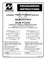
Only Keypad #1 may be used for both Dealer and User programming, however this keypad may be located in any area.
The Master Security Code is printed on the panel’s microprocessor can. Use this code to enter the Dealer Program Mode to program a
custom Dealer Security Code. Record the number, then remove the code label to prevent unauthorized access to the panel. If you
forget your Dealer Security Code, use the Master Security Code to enter programming.
After entering codes or data, press the save U button. Data will not be stored into memory unless U is pressed.
If the keypad is in the Program Mode and no activity is detected for longer than 4 minutes, a steady tone will sound.
Silence the sounder by the G button to continue, or by pressing the C button to exit.
A panel that has been COLD STARTED (Address Location 4093) performs identically to a new panel.
When programming a Multiple Area System, Direct Address Programming Mode must be used to complete the program.
KEYPAD #1: For ease of programming, it is recommended that a GEM-RP1CAe2 or GEM-K1CA be used as Keypad #1.
(Regardless of which keypad is selected, all new keypads are configured as Keypad #1 out of the box). If a GEM-RP2ASe2/
GEM-K2AS is used, configure address jumpers as Keypad #1 (see Configuring the GEM-RP2ASe2 Keypad, page 65).
1. Press EEEEEE R
2. Press "PRIOR/NO" button until “TURNON PROG Y/N” (GEM-RP2ASe2/
GEM-K2AS) or “17” (GEM-RP3DGTL/GEM-K3DGTL or
GEM-RP4RFC/GEM-K4RF) appears on the LCD screen.
3. Press "NEXT/YES" button to Enter Dealer Program Mode.
4. Press CC to exit Dealer Program Mode when finished.
•Number of Zones in Area 1
•Number of Zones in Area 2
•Fire Zones in Area 1
•2-Wire Fire Zones in Area 1
•Report All Zones to Central
•Exit/Entry Zones in Area 1
•Interior Zones in Area 1
•24 Hour Zones in Area 1
•Chime Zones in Area 1
•Chime 2 Zones in Area 1
•Exit/Entry2 Zones in Area 1
•50mS Loop Response Zones (Note: 750mS is
required for Loop Response time in UL installations).
•Aux Output Activated on Alarm Zones
•Sensor Watch Zones
•Keypad Sounder on Alarm Zones
•Auto Bypass re-entry Zones
•Enable no EOLR Zones
•Number of Keypads in Area 1 and 2
•Central Station Receiver 1 Tel. Number
•Central Station Receiver 1 Account Number
•Central Station Receiver 1 Format
•Enter User Codes
•RF Transmitter Points
•Quick Method (Enroll Method)
•Keyfob Transmitters
•Enter Zone Descriptions
•Dealer Code
•Enable Telco Line Fault Test
•Enable Burg Output Chirp on Keyfob
•Enable CP-01
NEW PANELS: The custom default program may be created for new panels only. Once the panel has been programmed by any
means, the number zones will be suppressed and cannot be changed. Should it be necessary to create a new custom default
program, (a) from the Dealer Program Mode, press the C button to enter the Direct Address Program Mode; (b) access Location
4091 (Clear Program); (c) press the U button and start over.
EASY MENU DRIVEN PROGRAM MODE
ACCESSING DEALER PROGRAM MODE
CUSTOMIZING A DEFAULT PROGRAM
For new panels, you can design a default program that will best suit your application. Using this procedure, you will configure the panel for:
This procedure will automatically set up system keypads, EZMs, wireless transmitters, etc. After your basic default program has
been loaded, you may alter it as necessary in the Direct Address Program Mode.
Master Security Code
(on microshield)
R
GEM-P3200
CONTROL
COMMUNCIATOR
MASTER SECURITY CODE
# - # - # - # - # - #

X GEM-P3200 Programming Instructions L NAPCO Security Systems
Page 6 WI1184B 2/06
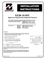
GEM-RP2ASe2/GEM-K2AS Keypad Easy Program Menu
Enter the Dealer Security Code (default = 456789) for a new panel or enter your custom Dealer Program Code if
programmed. Press the PRIOR/NO button repeatedly until “TURNON/PROG” is displayed. NOTE: If you pass
“TURNON/PROG”, you can scroll back by pressing B. Press the NEXT/YES button to enter the Dealer Program
Mode. In each of the following steps, press R to jump to the next screen, the NEXT/YES button to go
forwards, the PRIOR/NO button to go backwards, U to save and C twice to exit at any time.
R
COMPUTERIZED SECURITY SYSTEM
ARMED
STATUS
SYSTEM ARMED
01/01/97 12:00AM
12
4
3
56
7890
A
B
C
D
E
F
G
NEXT/YES
PRIOR/NO
AREA
GEMINI
ENT A1
ENT A1
GEM-RP2ASE2/GEM-K2AS KEYPAD EASY PROGRAM MENU
(Direct Entry)
Ent A1
#ZnXX
(Direct Entry)
Ent A2
#ZnXX
(Direct Entry)
Ent Fr
Zn#XX
(Direct Entry)
Ent2WF
Zn#XX
(Press YES or NO)
Report
all Zn
Y/N
(Direct Entry)
EntEE1
Zn#XX
(Direct Entry)
EntFol
Zn#XX
Total Number of Zones in Area 1 (New Program Only)
•Enter the total number of zones to be programmed for Area 1.
•Valid entries are from 08 to 48. Directly enter the total number of zones, including leading zeros.
•The system is based on groups of 4 zones each (after the first 8 zones), and will automatically round up to the
next group of 4. For example, if you enter 18, it will automatically convert this to 20 zones. Press U to save.
Press the NEXT/YES button to proceed.
Total Number of Zones in Area 2 (New Program Only)
•Enter the total number of zones to be programmed for Area 2.
•Valid entries are from 00 to 48. Directly enter the total number of zones, including leading zeros.
•The system is based on groups of 4 zones each (after the first 8 zones), and will automatically round up to the
next group of 4. For example, if you enter 18, it will automatically convert this to 20 zones. Press U to save.
Press the NEXT/YES button to proceed.
Fire Zones in Area 1 (New Program Only)
•Enter the zone number of any Fire Zones (including 2-wire, 4-wire or wireless).
•Valid entries are from 01 to 48.
•Directly enter each zone number, including leading zeros, and press U to save, and then repeat for any addi-
tional zone(s). Press the NEXT/YES button to proceed.
2-Wire Fire Zones in Area 1 (New Program Only)
•Enter the zone number of any Fire Zone (from previous question) to be used with 2-wire smoke detectors.
•Valid entries are 07 and 08. Directly enter each zone number, including leading zeros.
•Press U to save, and repeat for any additional zone(s); press NEXT to proceed.
NOTE: Only zones which have been designated as Fire Zones can be programmed as 2 Wire Fire zones. JP3
must be set to “2-WF” position for 2-wire fire for Zones 7-8 (refer to Installation Instructions).
Local or Central Station Reporting System (New Program Only)
Press the NEXT/YES button for all zones to report; press the PRIOR/NO button for local system.
Exit/Entry Zones in Area 1 (New Program Only)
•Enter the zone numbers of zones to be used as Exit/Entry zones.
•Valid entries are from 01 to 48. Directly enter each zone number, including leading zeros.
•Press U to save and repeat for any additional zone(s); press the NEXT/YES button to proceed.
NOTE: Entry Delay time of 30 seconds and Exit Delay Time of 60 seconds will automatically be programmed.
Interior Zones in Area 1 (New Program Only)
•Enter the zone numbers to be used as Interior Zones.
•Valid entries are from 01 to 48. Directly enter each zone number, including leading zeros.
•Press U to save and then repeat for any additional zone(s).
•Press the NEXT/YES button to proceed.
•All Interior zones will also be automatically programmed as “Exit/Entry Follower” and as "Power Up Delay" zones.

L NAPCO Security Systems X GEM-P3200 Programming Instructions
Page 7
WI1184B 2/06
24 Hour Zones in Area 1 (New Program Only)
•Enter the zone numbers of zones to be used as 24 Hour zones.
•Valid entries are from 01 to 48. Directly enter each zone number, including leading zeros.
•Press U to save and repeat for any additional zone(s); press the NEXT/YES button to proceed.
NOTE: 24 Hour Zones will automatically be programmed as audible (Burg Output).
Chime Zones in Area 1 (New Program Only)
•Enter the zone numbers which are to be used as Chime Zones.
•Valid entries are from 01 to 48. Directly enter each zone number, including leading zeros.
• Press U to save and then repeat for any additional zone(s), press the NEXT/YES button to proceed.
NOTE: A chime time of 2 seconds will be automatically programmed.
Chime 2 Zones in Area 1 (New Program Only)
•Enter the zone numbers which are to be used as Chime 2 Zones.
•Valid entries are from 01 to 48. Directly enter each zone number, including leading zeros.
•Press U to save and then repeat for any additional zone(s), press the NEXT/YES button to proceed.
NOTE: A chime time of 2 seconds will be automatically programmed.
Chime 2 zones give a distinct pulsating tone when zone is faulted.
Exit/Entry2 Zones in Area 1 (New Program Only)
•Enter the zone numbers of zones to be used as Exit/Entry zones.
•Valid entries are from 01 to 48. Directly enter each zone number, including leading zeros.
•Press U to save and repeat for any additional zone(s), press the NEXT/YES button to proceed.
NOTE: An Entry Delay Time of 30 seconds and an Exit Delay Time of 60 seconds will automatically be programmed.
50 mS Loop Response Zones (New Program Only)
•Enter the zone numbers of zones to have a 50mS loop response.
•Valid entries are from 01 to 08. Directly enter each zone number, including leading zeros.
•Press U to save and then repeat for any additional zone(s), press the NEXT/YES button to proceed. Note: Only panel
zones 01-08 can be programmed for Quick Loop Response. All other zones can be programmed via their respective
EZM's (hardwire). Note: 750mS is required for Loop Response time in UL installations.
Aux Output Activated on Alarm Zones (New Program Only)
•Enter the zone numbers of zones to activate the Aux Output upon alarm.
•Valid entries are from 01 to 48. Directly enter each zone number, including leading zeros.
•Press U to save and then repeat for any additional zone(s); press the NEXT/YES button to proceed.
NOTE: An Aux Output Timeout of 15 minutes will automatically be programmed.
Sensor Watch Zones (New Program Only)
•Enter the zone numbers of zones to be Sensor Watch zones.
•Valid entries are from 01 to 48. Directly enter each zone number, including leading zeros.
•Press U to save and then repeat for any additional zone(s), press the NEXT/YES button to proceed.
NOTE: A Sensor Watch Time of 24 hours will automatically be programmed.
Keypad Sounder On Alarm Zones (New Program Only)
•Enter the zone numbers of all zones to activate the Keypad Sounder upon alarm.
•Valid entries are from 01 to 48. Directly enter each zone number, including leading zeros.
•Press U to save and then repeat for any additional zone(s), press the NEXT/YES button to proceed.
Auto Bypass Re-entry Zones (New Program Only) (Not evaluated by UL)
•Enter the zone numbers of zones to be Auto Bypass Re-entry zones.
•Valid entries are from 01 to 48. Directly enter each zone number, including leading zeros.
•Press U to save and then repeat for any additional zone(s), press the NEXT/YES button to proceed.
•Auto Bypass Re-entry Zones allow the system to be armed with the zone faulted but come back into the system (armed)
when the zone is subsequently closed.
(Direct Entry)
Ent24H
Zn#XX
(Direct Entry)
EntCZ1
Zn#XX
(Direct Entry)
EntCZ2
Zn#XX
(Direct Entry)
EntEE2
Zn#XX
(Direct Entry)
Ent50m
Zn#XX
(Direct Entry)
EntAux
Zn#XX
(Direct Entry)
Ent SW
Zn#XX
(Direct Entry)
EntKPS
Zn#XX
(Direct Entry)
EntAUB
Zn#XX
GEM-RP2ASE2/GEM-K2AS KEYPAD EASY PROGRAM MENU

X GEM-P3200 Programming Instructions L NAPCO Security Systems
Page 8 WI1184B 2/06
Enable No EOLR Zones (New Program Only)
•Press YES to program all zones except 24 Hr & fire zones for No End Of Line Resistor. Press NO to continue.
•Do not program this feature for UL Installations.
Enable Telco Line Fault Test?
•Press YES to enable Telco Line Fault Test.
•Press NO to continue. NOTE: If enabled, a Telco Line Fault Test Delay of 60 sec. will automatically be pro-
grammed.
Enable Burg Output Chirp on KeyFob?
•Press the NEXT/YES button to enable Burg Output Chirp on KeyFob Arm / Disarm.
•Press the PRIOR/NO button to continue.
NOTE: The Burg Output will chirp once on Keyfob Arm and twice on Keyfob Disarm.
Enable SIA CP-01 Features?
•Press the NEXT/YES button to enable.
•Press the PRIOR/NO button to continue.
The SIA CP-01 Features are designed to reduce the incidence of false alarms. NOTE: Do not enable unless re-
porting, otherwise system trouble Fail to Communicate may occur.
Number of Keypads in Area 1
•Enter the total number of Keypads to be installed in Area 1.
•Valid entries are from 01 to 15. Directly enter the number of keypads, including leading zeros.
Press U to save. Press the NEXT/YES button to proceed.
Number of Keypads in Area 2
•Enter the total number of Keypads to be installed in Area 2.
•Valid entries are from 00 to 15. Directly enter the number of keypads, including leading zeros.
Press U to save. Press the NEXT/YES button to proceed. NOTE: Area 2 keypads must have zones in Area 2,
otherwise the keypad will indicate "Out of System".
Central Station Receiver 1 Telephone Number
•Enter telephone number of up to 16 digits.
•Press 1 through 9 for digits 1–9; G 0 for a zero and 0 for a blank (•).
•Press G 1 through G 5 for letters B–F, respectively.
•Pre-Dial Delay = “D” (G 4); Dial-Tone Detection = “E” (G 5).
•Press U to save and press the NEXT/YES button to proceed.
NOTE: Central Station Receiver 2 and 3 Telephone Numbers must be en-
tered in Direct Address Programming. See CS Receiver Options.
(Press YES or NO)
EnNEOL
Y/N
(Press YES or NO)
Telco
Ln Flt
Y/N
(Press YES or NO)
KF Out
Chirp
Y/N
(Press YES or NO)
Enable
CP01?
Y/N
(Direct Entry)
Ent A1
#KP 01
(Direct Entry)
Ent A2
#KP 01
(Direct Entry)
Phone#
______
______
GEM-RP2ASE2/GEM-K2AS KEYPAD EASY PROGRAM MENU

L NAPCO Security Systems X GEM-P3200 Programming Instructions
Page 9
WI1184B 2/06
Central Station Receiver 1 Account Number
•Enter an account number of up to four digits.
•Press 0 through 9 for digits 0–9, and G 0 for a blank (•).
•Press U to save and press the NEXT/YES button to proceed.
NOTE: Central Station Receiver 2 and 3 Account Numbers must be entered in Direct Address Programming. See
CS Reporting Options.
Central Station Receiver 1 Format
•From the table at the right enter the receiver format.
•Press 0 through 9, and G0 for blank (•).
•Press G1 through G4 for letters B–E.
•Press U to save and press the NEXT/YES button to proceed.
Easy Programming of Auto download ID #'s and PC Preset Callback Numbers (GEM-RP1CAe2 only)
For unattended PC Preset downloading, it is now possible to set the Auto download ID #’s and PC Preset Callback
from the Keypad Easy Program Mode.
•At the field for CENTRAL PHONE #, program an "F" followed by the Auto Download ID # (2 digits) and then the
Callback Telco # (up to 13 digits).
•Press D or U to save.
•Exit Program Mode (CC).
•Enter Master Code
•Press A or R
•Go to Function "ACTIVATE DOWNLOAD Y/N" and press YES (E or P).
•The panel will automatically call the PC Preset computer and download the program on the specified Auto
Download line # of PC Preset.
Example: Program an Auto download ID # of 07 and a PC Preset
Callback # of 1-516-842-9400
• Go to Central Phone # input screen and press: [*] [5] [0] [7] [1] [5] [1] [6] [8] [4] [2] [9] [4] [0] [0] D (or U).
CENTRAL PHONE #
F0715168429400
(Direct Entry)
Acc #
(____)
(Direct Entry)
RecFmt
( )
DATA
ENTRY
CS RECEIVER 1 FORMAT
blank(•) Ademco Slow, Silent Knight Slow
1 Sescoa, Vertex, DCI, Franklin
Fast
2 Radionics Fast
3 Silent Knight Fast
4 Radionics, DCI, Franklin Slow
5 Universal High Speed
8 Radionics BFSK
DATA
ENTRY
CS RECEIVER 1 FORMAT
9 FBI 4/3/1
0 Radionics Modem 2
B SIA
C Ademco Point ID
D Ademco Express
E Pager
NOTE: Modem IIe is available only in
Direct Address Programming. Central
Station Receiver 2 and 3 Formats can only
be entered in Direct Address
Programming. See CS Receiver Options.
GEM-RP2ASE2/GEM-K2AS KEYPAD EASY PROGRAM MENU

X GEM-P3200 Programming Instructions L NAPCO Security Systems
Page 10 WI1184B 2/06
Enter User Codes (Press the R button to set cursor.)
Enter up to 48 User Codes with User Options, Authority Level and Access Control Options
(if necessary) for each code. Refer to the tables below and on the next page for available
data entries for User Options, Authority Level and Access Control Options. Note: All 48
Users must be assigned to areas in “Enable User Code by Area” (Address 2500-2595) in
Direct Address Programming. By default, only User 1 is enabled in Area 1 and Area 2.
User 2 - 8 are enabled in Area 1 and user 9 - 16 are enabled in Area 2.
Press the R button to set the cursor to the User Code. Use the number buttons
1 through 9 to enter a code from 3 to 6 digits. Enter up to 6 digits in the first six
boxes from left to right for each user code. Valid entries are: 0-9. Note: Press the 0
button for a zero. No blank spaces in between; leave blank (•) any trailing boxes. If an
“Ambush Code” (Address 0495) is entered, do not program the first two digits of ANY
User Code as the same digits entered for the “Ambush Code”.
If the programmed code is less than 6 digits, press the R button to set the cursor to the OPTION/LEVEL.
Refer to the tables below for the available User Option and User Level data entries. Enter the user options data in
the left digit. Enter the level data (with arming options, if any, added) in the right digit. Note: For entries greater
than 9, press the G1 buttons through the G5 buttons for B through F, respectively.
For Keypad Access Control, press the R button once again to program applicable keypads. Refer to the tables
below, use the number buttons to enter the data for Keypad 1–4 in the right digit; and the data for Keypad 5–8 data
in the left digit. (Press the 0 buttons for blank).
USER OPTIONS
USER CODE
(UP TO 6 DIGITS)
USER
OPTION
USER
LEVEL
ACCESS CONTROL
KEYPADS
DATA
ENTRIES
AUTHORITY
LEVEL
CODE
TYPE
blank (•) NONE ARM/DISARM
1 LEVEL 1 ARM/DISARM
2 LEVEL 2 ARM/DISARM
3 LEVEL 3 ARM/DISARM
4 NONE ARM ONLY
5 LEVEL 1 ARM ONLY
6 LEVEL 2 ARM ONLY
7 LEVEL 3 ARM ONLY
8 NONE SERVICE
9 LEVEL 1 SERVICE
0 LEVEL 2 SERVICE
B LEVEL 3 SERVICE
C* NONE AMBUSH
D* LEVEL 1 AMBUSH
E* LEVEL 2 AMBUSH
F* LEVEL 3 AMBUSH
Note: “Y” indicates option is enabled.
USER OPTIONS
DATA
ENTRIES
BLOCKED
VIEW
USER
PROGRAM
BYPASS OVERVIEW
blank (•)
1 Y
2 Y
3 Y Y
4 Y
5 Y Y
6 Y Y
7 Y Y Y
8 Y
9 Y Y
0 Y Y
B Y Y Y
C Y Y
D Y Y Y
E Y Y Y
F Y Y Y Y
DISABLED
Note: “Y” indicates option is enabled.
ACCESS CONTROL KEYPADS
DATA
ENTRIES
K.P. 1 K.P. 2 K.P. 3 K.P. 4
blank (•)
1 Y
2 Y
3 Y Y
4 Y
5 Y Y
6 Y Y
7 Y Y Y
8 Y
9 Y Y
0 Y Y
B Y Y Y
C Y Y
D Y Y Y
E Y Y Y
F Y Y Y Y
NONE
Example: Enter a code of “123456” as
“123456” (from left to right).
Note: “Y” indicates option is enabled.
ACCESS CONTROL KEYPADS
DATA
ENTRIES
K.P. 5 K.P. 6 K.P. 7 K.P. 8
blank (•)
1 Y
2 Y
3 Y Y
4 Y
5 Y Y
6 Y Y
7 Y Y Y
8 Y
9 Y Y
0 Y Y
B Y Y Y
C Y Y
D Y Y Y
E Y Y Y
F Y Y Y Y
NONE
(Direct Entry)
User01
______
(Direct Entry)
OPT__
(Direct Entry)
ACC __
GEM-RP2ASE2/GEM-K2AS KEYPAD EASY PROGRAM MENU
*Note: These entries are only
available when address 3905 bit
7 is enabled.

L NAPCO Security Systems X GEM-P3200 Programming Instructions
Page 11
WI1184B 2/06
Example: Program a code of “2222” for user 02, with User Option of “User Program”, User “Level 3” and Access Control Option
“Keypad No. 1”. Enter “2222” for a user code, “2 3” for user option and “blank(•) 1” for access control option.
CHANGING OR CANCELING A CODE: To change any code, merely program over the existing code as described
above and press U to save. Similarly, to cancel a code, blank out each number of the code and press U to save to
save.
USER AUTHORITY LEVEL
FUNCTION LEVEL*
DISPLAY ZN FAULTS 1
DISPLAY ZN BYPASSED 1
DISPLAY ZN DIRECTORY 1
ACTIVATE BELL TEST 1
DISPLAY PHONE #’S 1
DISPLAY SYS TRBL 1
DISPLAY FIRE ALARM 1
DISPLAY FIRE TRBL 1
DISPLAY OP/CL 3
ACTIVATE OVERVIEW 3**
ACTIVATE CHIME 1
ACTIVATE WATCH 2
RESET SYSTEM TRBL 3
RESET SENSOR MSG 3
START EXIT TIME 1
FAULT FIND ***
ACTIVATE LOCATE ***
EZM ZONE FIND ***
ACTIVATE DIALER TEST 3
DISPLAY ALARM LOG 3
DISPLAY TOTAL LOG 3
DISPLAY FIRE LOG 3
DISPLAY OP/CL LOG 3
DISPLAY SYSTEM LOG 3
AUTOARM IN 1-4HRS 2
DISPLAY AUTOARM SCHD 3
ACTIVATE PROGRAM 3**
ACTIVATE DOWNLOAD 3
DISPLY RF XMITTER STAT 1
RELAY CONTROL 1
KEYPAD DISPLAY FUNCTION MENU NOTES:
* Minimum Level required to access function
** Level-3 Code with appropriate user option
*** Requires Dealer Code
Related User Options: “Ambush Code” (Address 0495), “Panel Access
Code” (Address 0490), “Dealer Security Code” (Address 0500) & “Enable User Code by
Area” (Address 2500-2595).
OPTIONS EXPLANATION
Disabled User Code not active in this area.
Blocked View Allows User Code to block another code from being viewed by another user.
An unblocked code cannot view a blocked code, but a blocked code can
view all codes. The master user code and the dealer program code can view
all codes.
User Program User Program Option is enabled for Keypad 1 only, wherever it is connected
(any area). If enabled, Level 3 must also be enabled.
Bypass Allows User Code to bypass zones.
Overview This option, along with Level 3 Authorization, enables selection of
OVERVIEW mode at a keypad. This Mode provides a system status display
of all areas at a glance.
Arm Only Prevents User Code from disarming this area.
Service A Service Code has restricted arm/disarm rights; if an area is armed with a
Service Code, a “SERVICE ON” appears on the GEM-RP2ASe2 keypad (a “S”
on the GEM-RP1CAe2 keypad) and the area can be disarmed with any valid
User Code, including a Service Code. If the area is armed with OTHER than
a Service Code, it CANNOT be disarmed with a Service Code. This is
typically used to allow tradesmen access to premises under control of the
owner.
Access This is normally used to activate a door striker while an area is disarmed. A
code with the access option will not function as an arm/disarm code. When
the code is entered, the keypad will display “ENTER NOW” and the Brown
Wire on the keypad will become Active Low (Ground Potential) for 7
seconds.
USER OPTIONS
Ambush There are two types of Ambush Codes: (1) A 2-digit code (prefix) that is entered
immediately prior to (and as part of) the regular User Code and (2) A separate
and unique User Code. Disarming with an Ambush Code will cause a silent
report to be sent to a central station. Thus, should a user be forced to disarm, he
can silently signal an emergency while appearing to be merely disarming the
system.
GEM-RP2ASE2/GEM-K2AS KEYPAD EASY PROGRAM MENU

X GEM-P3200 Programming Instructions L NAPCO Security Systems
Page 12 WI1184B 2/06
USER OPTIONS
USER CODE
(UP TO 6 DIGITS)
USER
LEVEL
ACM AREA
DATA
ENTRIES
ACCESS
LEVEL
CODE
TYPE
blank (•) 0 NONE
1 1 NONE
2 2 NONE
4 0 ARM/DISARM
5 1 ARM/DISARM
6 2 ARM/DISARM
8 0 ARM ONLY
9 1 ARM ONLY
0 2 ARM ONLY
Note: “Y” indicates option is enabled.
ACM AREA
DATA
ENTRIES
A1 A2
blank (•) NONE
1 Y
2 Y
3 Y Y
4
5 Y
6 Y
7 Y Y
8
9 Y
0 Y
B Y Y
C
D Y
E Y
F Y Y
Example: Enter a code of “123456”
as “123456” (from left to right).
GEM-RP2ASE2/GEM-K2AS KEYPAD EASY PROGRAM MENU
Enter Proximity Card Users (FOR ACM USE ONLY).
(Press the R button to set cursor). See WI1221 for more information.
Enter up to 48 Proximity Cards with User Options, Access Level and ACM
Area (if necessary) for each card. Refer to the tables below and to WI1221 for
more information.
Press the R button to set the cursor to the User Code. Use the number buttons 1 through 9 to enter
a 6 digit code. Enter the digits in the first six boxes from left to right for each user code. Valid entries are: 0-9.
Note: Press the 0 button for a zero. No blank spaces in between; leave blank (•) any trailing boxes.
Refer to the tables below and WI1221 for the available User Level data entries. Enter the level data in the right
digit. Leave blank (•) in the left digit. Note: For entries greater than 9, press the G1 buttons through the
G5 buttons for B through F, respectively.
For ACM Area, enter data for area 1-4 in the right digit and data for area 5-8 in the left digit. See table below.
Enter user code
001 123456- 6-
User# User Code

L NAPCO Security Systems X GEM-P3200 Programming Instructions
Page 13
WI1184B 2/06
GEM-RP2ASE2/GEM-K2AS KEYPAD EASY PROGRAM MENU
RF Transmitter Points (Press R to set cursor.)
For each transmitter enter: (For wireless systems only. Also see Quick Method, which follows)
•The zone number (01–48) to which the transmitter will be mapped.
•The 6-digit RF ID # and 1-digit checksum number printed on the transmitter and box,
•The point number (1–2); enter “9” for unsupervised (all points).
•Press U to save and NEXT/YES button to proceed when all transmitters have been entered.
NOTE: When programming the ID Code number, “0” through ”9” = 0 through 9; A = G0 ; B
= G1 ; C = G2 ; D = G3 ; E = G4 and “F” = G5.
Quick Method (Enroll Method). If a receiver is already installed in the panel, transmitter wireless
points can be programmed automatically (“enrolled”) using the following procedure. NOTE: The transmitter
point will be enrolled only if the signal strength is 3 or greater.
1. Enter the zone number to which the transmitter point will be mapped.
2. Press B to enter the Enroll Mode. The red and green LEDs on the keypad will flash and the window will
display as shown at left.
3. Open the loop of the point that is to be programmed (GEM-TRANS2 only).
4. Install the transmitter battery. The keypad will beep to indicate that the point has been successfully enrolled.
Multi-point transmitters can be mapped to successive zones simultaneously.
Keyfob Transmitters as Arm/Disarm & Control Devices (Press R to set cursor).
Keyfobs can be programmed as “Arm/Disarm” devices using their On/Off buttons (refer to WI752). For each
Keyfob Transmitter, enter:
•The Keyfob Transmitter number (01–16).
•The area number to which transmitter is assigned (0 to disable keyfob, 1 or 2).
•The 6-digit RF ID # and 1-digit checksum number printed on the transmitter and box,
•The Aux 1 Option (see keyfob aux 1 & aux 2 options).
•The Aux 2 Option (see keyfob aux 1 & aux 2 options).
•Press U to save and NEXT/YES button to proceed when all keyfobs have been entered.
NOTE: When programming the ID Code number, “0” through ”9” = 0 through 9; A = G0;
B = G1; C = G2; D = G3; E = G4 and “F” = G5.
ZN# XMIT#+CS P
Zn01- 000000:0-0
ZN# XMIT#+CS P
ZN01- ENROLL:A--
Example. A 2-point transmitter has the RF ID number 287613:1. Map
point 1 to Zone 6 and point 2 to Zone 9.
1. Enter the Enroll mode as described above.
2. Enter Zone “06”.
3. Open point-1 loop.
4. Install the battery. The keypad will beep once to indicate that one point
has been programmed. (Transmitter 287613:1, point 1 will be mapped
to Zone 6).
5. Enter Zone “09”.
6. Close point-1 loop and open point-2 loop.
7. Remove the transmitter battery, then re-install it. The keypad will beep
once to indicate that one point has been programmed. (Transmitter
287613:1, point 2 is mapped to Zone 9).
KEYFOB ZONE ASSIGNMENT: Keyfobs can also be assigned to zones to allow multiple wireless panic buttons on one alarm
system, each reporting to a central station, a pager or having a description on the keypad that describes the person holding the
keyfob, the location where the person holding the keyfob is stationed, or the special purpose of the keyfob button being de-
pressed. See the next page on Keyfob Transmitters as Zone Input Devices .
(Direct Entry)
Zn# 01
000000
(Direct Entry)
:0 Pt
(Direct Entry)
KFob01
Area
(Direct Entry)
000000
(Direct Entry)
:0 0 0

X GEM-P3200 Programming Instructions L NAPCO Security Systems
Page 14 WI1184B 2/06
Keyfob Transmitters as Zone Input Devices
(Refer to display above: press the PRIOR button to go backwards).
Each of the 4 keyfob buttons can be assigned to a zone. For example, On button = point
1; Off button = point 2; A1 = point 3; A2 = point 4. Up to 48 keyfobs (using 1 button) or 24
keyfobs (using 2 buttons) or 14 keyfobs (using all 4 buttons) or any combination up to a
maximum of 48 controlled zones can be assigned, providing multiple wireless panic but-
tons on a system, each reporting to a Central Station or a pager and/or annunciating on a
keypad the keyfob zone number with a description. To assign a keyfob to a zone: pro-
gram the keyfob as you would a transmitter, entering the keyfob's ID code, check sum and
point number at the appropriate zone. The “Quick Method” is not allowed. The zone may
be hardwired to an electrical sensor as well as assigned to a keyfob (either one will acti-
vate the zone alarm output). NOTE: If assigning a keyfob to a zone, the “ON/OFF” but-
tons on the keyfob will no longer arm/disarm the system. The keyfob is converted to a
“panic only” device.
Enter Date (Press R to set cursor).
•Enter the current date in the format MM/DD/YY. (MM = month, DD = day and YY = year.
•Press U to save. Press the NEXT/YES button to proceed.
Enter Time (Press R to set cursor.)
•Enter the current time in format HH:MMA/P, where HH=hours (01–12); MM=minutes (00–59).
•Select AM or PM by pressing any number button to toggle selection.
•Press U to save. Press the NEXT/YES button to proceed.
Dealer Code
•Directly enter the Dealer Code (default = 456789), using 0 through 9 buttons.
•Press U to save.
•Re-enter the Dealer Code to verify the previous code.
•Press U to save.
•Press the NEXT/YES button to proceed.
(Direct Entry)
Enter Date
( / / )
(Direct Entry)
Enter Time
( : )
Dealer Code
456789
DEALER CODE
RE-ENTER
CLEAR PROGRAM: Should it be necessary to create a new custom default program, (a) from the Dealer Program Mode, press C to en-
ter the Address Program Mode; (b) access Location 4091 (Clear Program) or 1093 (Cold Start); (c) press U and then (d) press C to exit the
Dealer Program Mode. A “SYSTEM TROUBLE/E09-00 SERVICE” will occur. Press C to silence the keypad.
Clear Dealer Program (Erases Dealer Program)
Use this feature to erase the Panel Program, while maintaining Scheduled Data and Zone Descriptions. Ac-
cess address 4091 and press U. Data entry is not allowed. NOTE: Enter Easy Menu Driven Pro-
gram Mode to reprogram system.
Cold Start (Erases Entire Program)
This erases all programmed data (Dealer Program, Zone Description Data and Schedules). Access
address 4093 and press U. Data entry is not allowed. NOTE: Some features (schedules) can only be
programmed again with the Downloading Software.
EXIT DEALER PROGRAM MODE: This completes the custom default program. Press C to enter the Direct Address Pro-
gram Mode for further programming or press C once again to end all programming and resume normal keypad operation.
4091 XX H
4093 XX H
DATA ENTRY AUX 1/AUX 2 OPTIONS
0 None
1 Relay Group 1 Toggle
2 Relay Group 2 Toggle
3 Relay Group 3 Toggle
4 Relay Group 4 Toggle
5 Relay Group 5 Toggle
6 Relay Group 6 Toggle
7 Relay Group 7 Toggle
8 Relay Group 8 Toggle
9 Panic
A Auxiliary
B Instant
C Aux. Output Toggle
D Access on Aux. Output
E Arm STAY ("K Series" Keypads Only)
F Interior Bypass ("Classic" RP Series
Keypads only)
ZONE DESCRIPTIONS: GEM-RP2ASe2/GEM-K2AS cannot be used to enter Zone Descriptions. To enter Zone Descriptions,
you must use the GEM-RP1CAe2/GEM-K1CA Keypad (See WI818) or the PCD-Windows Quickloader Software.
GEM-RP2ASE2/GEM-K2AS KEYPAD EASY PROGRAM MENU

L NAPCO Security Systems X GEM-P3200 Programming Instructions
Page 15
WI1184B 2/06
GEM-RP3DGTL/GEM-K3DGTL and GEM-RP4RFC/GEM-K4RF Keypad Easy Program Menu
To enter Dealer Program Mode, see page 5. Once entered, press R, followed by [PRIOR/NO] repeatedly until “17” is displayed (scroll back
by pressing B). Press [NEXT] to enter Easy Program Mode. For the GEM-RP3DGTL/GEM-K3DGTL (and GEM-RP4RFC/GEM-K4RF),
questions are in the form of a 2-digit number flashing in the display. Press R to set the cursor into the next field to answer the question.
Press R again to scroll through each segment. Press [NEXT] to go to the next question. To review your Easy Program Mode responses
(before pressing U to save), press R until the 2-digit question number flashes in the display again. If the data is correct, press U to save.
If the data is incorrect, press R to set the cursor into the next field and again enter your data. Note: Review your Easy Program Mode re-
sponses after the initial programming of the control, except for questions marked "For New Panel Only". These questions set up the basic struc-
ture of the panel program ("Number of Zones in an Area", etc.) and cannot be viewed or altered once set. To exit Dealer Program Mode, press
C twice. To return the panel to the factory default, enter the Direct Address Program Mode, go to location 1198 and press U.
(Direct Entry)
07
INTERIOR BYPASS FIRE/TBL SYS TBL CHIME
INTERIOR BYPASS FIRE/TBL SYS TBL CHIME
H
(Direct Entry)
05
INTERIOR BYPASS FIRE/TBL SYS TBL CHIME
INTERIOR BYPASS FIRE/TBL SYS TBL CHIME
H
(Direct Entry)
04
INTERIOR BYPASS FIRE/TBL SYS TBL CHIME
INTERIOR BYPASS FIRE/TBL SYS TBL CHIME
H
(Direct Entry)
01
INTERIOR BYPASS FIRE/TBL SYS TBL CHIME
INTERIOR BYPASS FIRE/TBL SYS TBL CHIME
Flashing
H
GEM-RP3DGTL/GEM-K3DGTL AND GEM-RP4RFC/GEM-K4RF KEYPAD EASY PROGRAM MENU
(Direct Entry)
02
INTERIOR BYPASS FIRE/TBL SYS TBL CHIME
INTERIOR BYPASS FIRE/TBL SYS TBL CHIME
H
(Direct Entry)
06
INTERIOR BYPASS FIRE/TBL SYS TBL CHIME
INTER IOR BYPASS FIRE/TBL SYS TBL CHIME
H
Total Number of Zones in Area 1 (New Program Only)
•Enter the total number of zones to be programmed for Area 1.
•Valid entries are from 08 to 48. Directly enter the total number of zones, including leading zeros.
•The system is based on groups of 4 zones each (after the first 8 zones), and will automatically round
up to the next group of 4. For example, if you enter 18, it will automatically convert this to 20 zones.
Press U to save. Press the NEXT/YES button to proceed.
Total Number of Zones in Area 2 (New Program Only)
•Programming Area 2 is identical to Area 1 above.
Press the NEXT/YES button to proceed.
Fire Zones in Area 1 (New Program Only)
•Enter the zone number of any Fire Zones (including 2-wire, 4-wire or wireless).
•Valid entries are from 01 to 48.
•Directly enter each zone number, including leading zeros, and press U to save, and then repeat for
any additional zone(s). Press the NEXT/YES button to proceed.
2-Wire Fire Zones in Area 1 (New Program Only)
•Enter the zone number of any Fire Zone (from previous question) to be used with 2-wire smoke de-
tectors.
•Valid entries are 07 and 08. Directly enter each zone number, including leading zeros.
•Press U to save, and repeat for any additional zone(s); press NEXT to proceed.
NOTE: Only zones which have been designated as Fire Zones can be programmed as 2 Wire Fire zones.
JP3 must be set to “2-WF” position for 2-wire fire for Zones 7-8 (refer to Installation Instructions).
Local or Central Station Reporting System (New Program Only)
•Press the NEXT/YES button for all zones to report; press the PRIOR/NO button for local system.
Exit/Entry Zones in Area 1 (New Program Only)
•Enter the zone numbers of zones to be used as Exit/Entry zones.
•Valid entries are from 01 to 48. Directly enter each zone number, including leading zeros.
•Press U to save and repeat for any additional zone(s); press the NEXT/YES button to proceed.
NOTE: Entry Delay Time of 30 seconds and Exit Delay Time of 60 seconds will automatically be pro-
grammed.

X GEM-P3200 Programming Instructions L NAPCO Security Systems
Page 16 WI1184B 2/06
Interior Zones in Area 1 (New Program Only)
•Enter the zone numbers to be used as Interior Zones.
•Valid entries are from 01 to 48. Directly enter each zone number, including leading zeros.
•Press U to save and then repeat for any additional zone(s). Press the NEXT/YES button to proceed.
•All Interior zones will also be automatically programmed as “Exit/Entry Follower” and as "Power Up Delay"
zones.
24 Hour Zones in Area 1 (New Program Only)
•Enter the zone numbers of zones to be used as 24 Hour zones.
•Valid entries are from 01 to 48. Directly enter each zone number, including leading zeros.
•Press U to save and repeat for any additional zone(s); press the NEXT/YES button to proceed.
NOTE: 24 Hour Zones will automatically be programmed as audible (Burg Output).
Chime Zones in Area 1 (New Program Only)
•Enter the zone numbers which are to be used as Chime Zones.
•Valid entries are from 01 to 48. Directly enter each zone number, including leading zeros.
• Press U to save and then repeat for any additional zone(s), press the NEXT/YES button to proceed.
NOTE: A chime time of 2 seconds will be automatically programmed.
Chime 2 Zones in Area 1 (New Program Only)
•Enter the zone numbers which are to be used as Chime 2 Zones.
•Valid entries are from 01 to 48. Directly enter each zone number, including leading zeros.
•Press U to save and then repeat for any additional zone(s), Press the NEXT/YES button to proceed.
NOTE: A chime time of 2 seconds will be automatically programmed.
Chime 2 zones give a distinct pulsating tone when zone is faulted.
Exit/Entry2 Zones in Area 1 (New Program Only)
•Enter the zone numbers of zones to be used as Exit/Entry zones.
•Valid entries are from 01 to 48. Directly enter each zone number, including leading zeros.
•Press U to save and repeat for any additional zone(s); press the NEXT/YES button to proceed.
NOTE: An Entry Delay Time of 30 seconds and an Exit Delay Time of 60 seconds will automatically be pro-
grammed.
50 mS Loop Response Zones (New Program Only)
•Enter the zone numbers of zones to be have a 50mS loop response.
•Valid entries are from 01 to 08. Directly enter each zone number, including leading zeros.
•Press U to save and then repeat for any additional zone(s), Press the NEXT/YES button to proceed. Note:
Only panel zones 01-08 can be programmed for Quick Loop Response. All other zones can be programmed
via their respective EZM's (hardwire). Note: 750mS is required for Loop Response time in UL in-
stallations.
Aux Output Activated on Alarm Zones (New Program Only)
•Enter the zone numbers of zones to activate the PGM2 upon alarm.
•Valid entries are from 01 to 48. Directly enter each zone number, including leading zeros.
•Press U to save and then repeat for any additional zone(s), Press the NEXT/YES button to proceed.
NOTE: A PGM2 Timeout of 15 minutes will automatically be programmed.
Sensor Watch Zones (New Program Only)
•Enter the zone numbers of zones to be Sensor Watch zones.
•Valid entries are from 01 to 48. Directly enter each zone number, including leading zeros.
•Press U to save and then repeat for any additional zone(s), Press the NEXT/YES button to proceed.
NOTE: A Sensor Watch Time of 24 hours will automatically be programmed.
(Direct Entry)
08
INTER IOR BYPASS FIRE/TBL SYS TBL CHIME
INTERIOR BYPASS FIRE/TBL SYS TBL CHIME
H
(Direct Entry)
(Direct Entry)
14
INTER IOR BYPASS FIRE/TBL SYS TBL CHIME
INTERIOR BYPASS FIRE/TBL SYS TBL CHIME
H
(Direct Entry)
13
INTER IOR BYPASS FIRE/TBL SYS TBL CHIME
INTERIOR BYPASS FIRE/TBL SYS TBL CHIME
H
(Direct Entry)
12
INTER IOR BYPASS FIRE/TBL SYS TBL CHIME
INTERIOR BYPASS FIRE/TBL SYS TBL CHIME
H
(Direct Entry)
11
INTER IOR BYPASS FIRE/TBL SYS TBL CHIME
INTERIOR BYPASS FIRE/TBL SYS TBL CHIME
H
(Direct Entry)
09
INTER IOR BYPASS FIRE/TBL SYS TBL CHIME
INTERIOR BYPASS FIRE/TBL SYS TBL CHIME
H
10
INTER IOR BYPASS FIRE/TBL SYS TBL CHIME
INTERIOR BYPASS FIRE/TBL SYS TBL CHIME
H
(Direct Entry)
15
INTER IOR BYPASS FIRE/TBL SYS TBL CHIME
INTERIOR BYPASS FIRE/TBL SYS TBL CHIME
H
GEM-RP3DGTL/GEM-K3DGTL AND GEM-RP4RFC/GEM-K4RF KEYPAD EASY PROGRAM MENU

L NAPCO Security Systems X GEM-P3200 Programming Instructions
Page 17
WI1184B 2/06
Keypad Sounder On Alarm Zones (New Program Only)
•Enter the zone numbers of all zones to activate the Keypad Sounder upon alarm.
•Valid entries are from 01 to 48. Directly enter each zone number, including leading zeros.
•Press U to save and then repeat for any additional zone(s), Press the NEXT/YES button to proceed.
Auto Bypass Re-entry Zones (New Program Only) (Not evaluated by UL)
•Enter the zone numbers of zones to be Auto Bypass Re-entry zones.
•Valid entries are from 01 to 48. Directly enter each zone number, including leading zeros.
•Press U to save and then repeat for any additional zone(s), Press the NEXT/YES button to proceed.
•Auto Bypass Re-entry Zones allow the system to be armed with the zone faulted but come back into the system
(armed) when the zone is subsequently closed.
Enable No EOLR Zones (New Program Only)
•Press YES to program all zones except 24 Hr & fire zones for No End Of Line Resistor. Press NO to continue.
•Do not program this feature for UL Installations.
Enable Telco Line Fault Test?
•Press YES to enable Telco Line Fault Test.
•Press NO to continue.
NOTE: If enabled, a Telco Line Fault Test Delay of 60 seconds will automatically be programmed.
Enable Burg Output Chirp on KeyFob?
•Press the NEXT/YES button to enable Burg Output Chirp on KeyFob Arm / Disarm.
•Press the PRIOR/NO button to continue.
NOTE: The Burg Output will chirp once on Keyfob Arm and twice on Keyfob Disarm.
Enable SIA CP-01 Features?
•Press the NEXT/YES button to enable.
•Press the PRIOR/NO button to continue.
The SIA CP-01 Features are designed to reduce the incidence of false alarms. NOTE: Do not enable unless
reporting, otherwise system trouble Fail to Communicate may occur.
Number of Keypads in Area 1
•Enter the total number of Keypads to be installed in Area 1.
•Valid entries are from 01 to 07. Directly enter the number of keypads, including leading zeros.
Press U to save. Press the NEXT/YES button to proceed.
Number of Keypads in Area 2
•Enter the total number of Keypads to be installed in Area 2.
•Valid entries are from 00 to 07. Directly enter the number of keypads, including leading zeros.
Press U to save. Press the NEXT/YES button to proceed. NOTE: Area 2 keypads must have zones in
Area 2, otherwise the keypad will indicate "Out of System".
(Direct Entry)
16
INTERIOR BYPASS FIRE/TBL SYS TBL CHIME
INTER IOR BYPASS FIRE/TBL SYS TBL CHIME
H
(Direct Entry)
17
INTERIOR BYPASS FIRE/TBL SYS TBL CHIME
INTER IOR BYPASS FIRE/TBL SYS TBL CHIME
H
(Press YES or NO)
18
INTER IOR BYPASS FIRE/TBL SYS TBL CHIME
(Press YES or NO)
19
INTERIOR BYPASS FIRE/TBL SYS TBL CHIME
(Press YES or NO)
20
INTERIOR BYPASS FIRE/TBL SYS TBL CHIME
(Press YES or NO)
21
INTERIOR BYPASS FIRE/TBL SYS TBL CHIME
(Direct Entry)
22
INTERIOR BYPASS FIRE/TBL SYS TBL CHIME
INTER IOR BYPASS FIRE/TBL SYS TBL CHIME
_ H
(Direct Entry)
23
INTERIOR BYPASS FIRE/TBL SYS TBL CHIME
INTER IOR BYPASS FIRE/TBL SYS TBL CHIME
_ H
GEM-RP3DGTL/GEM-K3DGTL AND GEM-RP4RFC/GEM-K4RF KEYPAD EASY PROGRAM MENU

X GEM-P3200 Programming Instructions L NAPCO Security Systems
Page 18 WI1184B 2/06
Central Station Receiver 1 Telephone Number
•Enter telephone number of up to 16 digits.
•Press 1 through 9 for digits 1–9; G 0 for a zero and 0 for a blank (•).
•Press G 1 through G 5 for letters B–F, respectively.
•Pre-Dial Delay = “D” (G 4); Dial-Tone Detection = “E” (G 5).
•Press U to save and press the NEXT/YES button to proceed.
NOTE: Central Station Receiver 2 and 3 Telephone Numbers must be entered in Direct Address Program-
ming. See CS Receiver Options.
Central Station Receiver 1 Account Number
•Enter an account number of up to four digits.
•Press 0 through 9 for digits 0–9, and G 0 for a blank (•).
•Press U to save and press the NEXT/YES button to proceed.
NOTE: Central Station Receiver 2 and 3 Account Numbers must be entered in Direct Address Program-
ming. See CS Reporting Options.
Central Station Receiver 1 Format
•From the table at the right enter the receiver format.
•Press 0 through 9, and G0 for blank (•).
•Press G1 through G4 for letters B–E.
•Press U to save and press the NEXT/YES button to proceed.
DATA
ENTRY
CS RECEIVER 1 FORMAT
blank(•) Ademco Slow, Silent Knight Slow
1 Sescoa, Vertex, DCI, Franklin
Fast
2 Radionics Fast
3 Silent Knight Fast
4 Radionics, DCI, Franklin Slow
5 Universal High Speed
8 Radionics BFSK
DATA
ENTRY
CS RECEIVER 1 FORMAT
9 FBI 4/3/1
0 Radionics Modem 2
B SIA
C Ademco Point ID
D Ademco Express
E Pager
NOTE: Modem IIe is available only in
Direct Address Programming. Central
Station Receiver 2 and 3 Formats can only
be entered in Direct Address
Programming. See CS Receiver Options.
(Direct Entry)
25
INTER IOR BYPASS FIRE/TBL SYS TBL CHIME
INTERIOR BYPASS FIRE/TBL SYS TBL CHIME
_ 3
(Direct Entry)
26
INTER IOR BYPASS FIRE/TBL SYS TBL CHIME
INTERIOR BYPASS FIRE/TBL SYS TBL CHIME
8
GEM-RP3DGTL/GEM-K3DGTL AND GEM-RP4RFC/GEM-K4RF KEYPAD EASY PROGRAM MENU
(Direct Entry)
24
INTER IOR BYPASS FIRE/TBL SYS TBL CHIME
INTERIOR BYPASS FIRE/TBL SYS TBL CHIME
_ 3

L NAPCO Security Systems X GEM-P3200 Programming Instructions
Page 19
WI1184B 2/06
Enter User Codes (Press the R button to set cursor.)
Enter up to 48 User Codes with User Options, Authority Level and Access Control
Options (if necessary) for each code. Refer to the tables below and on the next page
for available data entries for User Options, Authority Level and Access Control
Options. Note: All 48 Users must be assigned to areas in “Enable User Code by
Area” (Address 2500-2595) in Direct Address Programming. By default, only User 1 is
enabled in Area 1 and Area 2.
User 2 - 8 are enabled in Area 1 and user 9 - 16 are enabled in Area 2.
Press the R button to set the cursor to the User Code. Use the number buttons 1 through 9 to enter
a code from 3 to 6 digits. Enter up to 6 digits (4 digits is recommended) in the first six boxes from left to right for
each user code. Valid entries are: 0-9. Note: Press the 0 button for a zero. No blank spaces in between;
leave blank (•) any trailing boxes. If an “Ambush Code” (Address 0495) is entered, do not program the first two
digits of ANY User Code as the same digits entered for the “Ambush Code”.
If the programmed code is less than 6 digits, press the R button to set the cursor to the OPTION/LEVEL.
Refer to the tables below for the available User Option and User Level data entries. Enter the user options data in
the left digit. Enter the level data (with arming options, if any, added) in the right digit. Note: For entries greater
than 9, press the G1 buttons through the G5 buttons for B through F, respectively.
For Keypad Access Control, press the R button once again to program applicable keypads. Refer to the
tables below, use the number buttons to enter the data for Keypad 1–4 in the right digit; and the data for Keypad
5–8 data in the left digit. (Press the 0 buttons for blank).
USER OPTIONS
USER CODE
(UP TO 6 DIGITS)
USER
OPTION
USER
LEVEL
ACCESS CONTROL
KEYPADS
DATA
ENTRIES
AUTHORITY
LEVEL
CODE
TYPE
blank (•) NONE ARM/DISARM
1 LEVEL 1 ARM/DISARM
2 LEVEL 2 ARM/DISARM
3 LEVEL 3 ARM/DISARM
4 NONE ARM ONLY
5 LEVEL 1 ARM ONLY
6 LEVEL 2 ARM ONLY
7 LEVEL 3 ARM ONLY
8 NONE SERVICE
9 LEVEL 1 SERVICE
0 LEVEL 2 SERVICE
B LEVEL 3 SERVICE
Note: “Y” indicates option is enabled.
USER OPTIONS
DATA
ENTRIES
BLOCKED
VIEW
USER
PROGRAM
BYPASS OVERVIEW
blank (•)
1 Y
2 Y
3 Y Y
4 Y
5 Y Y
6 Y Y
7 Y Y Y
8 Y
9 Y Y
0 Y Y
B Y Y Y
C Y Y
D Y Y Y
E Y Y Y
F Y Y Y Y
DISABLED
Note: “Y” indicates option is enabled.
ACCESS CONTROL KEYPADS
DATA
ENTRIES
K.P. 1 K.P. 2 K.P. 3 K.P. 4
blank (•)
1 Y
2 Y
3 Y Y
4 Y
5 Y Y
6 Y Y
7 Y Y Y
8 Y
9 Y Y
0 Y Y
B Y Y Y
C Y Y
D Y Y Y
E Y Y Y
F Y Y Y Y
NONE
Example: Enter a code of “123456” as
“123456” (from left to right).
Note: “Y” indicates option is enabled.
ACCESS CONTROL KEYPADS
DATA
ENTRIES
K.P. 5 K.P. 6 K.P. 7 K.P. 8
blank (•)
1 Y
2 Y
3 Y Y
4 Y
5 Y Y
6 Y Y
7 Y Y Y
8 Y
9 Y Y
0 Y Y
B Y Y Y
C Y Y
D Y Y Y
E Y Y Y
F Y Y Y Y
NONE
(Direct Entry)
27
INTERIOR BYPASS FIRE/TBL SYS TBL CHIME
INTER IOR BYPASS FIRE/TBL SYS TBL CHIME
GEM-RP3DGTL/GEM-K3DGTL AND GEM-RP4RFC/GEM-K4RF KEYPAD EASY PROGRAM MENU

X GEM-P3200 Programming Instructions L NAPCO Security Systems
Page 20 WI1184B 2/06
Example: Program a code of “2222” for user 02, with User Option of “User Program”, User “Level 3” and Access Control Option
“Keypad No. 1”. Enter “2222” for a user code, “2 3” for user option and “blank(•) 1” for access control option.
CHANGING OR CANCELING A CODE: To change any code, merely program over the existing code as described
above and press U to save. Similarly, to cancel a code, blank out each number of the code and press U to save to
save.
USER AUTHORITY LEVEL
FUNCTION LEVEL*
DISPLAY ZN FAULTS 1
DISPLAY ZN BYPASSED 1
DISPLAY ZN DIRECTORY 1
ACTIVATE BELL TEST 1
DISPLAY PHONE #’S 1
DISPLAY SYS TRBL 1
DISPLAY FIRE ALARM 1
DISPLAY FIRE TRBL 1
DISPLAY OP/CL 3
ACTIVATE OVERVIEW 3**
ACTIVATE CHIME 1
ACTIVATE WATCH 2
RESET SYSTEM TRBL 3
RESET SENSOR MSG 3
START EXIT TIME 1
FAULT FIND ***
ACTIVATE LOCATE ***
EZM ZONE FIND ***
ACTIVATE DIALER TEST 3
DISPLAY ALARM LOG 3
DISPLAY TOTAL LOG 3
DISPLAY FIRE LOG 3
DISPLAY OP/CL LOG 3
DISPLAY SYSTEM LOG 3
AUTOARM IN 1-4HRS 2
DISPLAY AUTOARM SCHD 3
ACTIVATE PROGRAM 3**
ACTIVATE DOWNLOAD 3
DISPLY RF XMITTER STAT 1
RELAY CONTROL 1
KEYPAD DISPLAY FUNCTION MENU NOTES:
* Minimum Level required to access function
** Level-3 Code with appropriate user option
*** Requires Dealer Code
Related User Options: “Ambush Code” (Address 0495), “Panel Access Code” (Address
0490), “Dealer Security Code” (Address 0500) & “Enable User Code by Area” (Address
2500-2595).
OPTIONS EXPLANATION
Disabled User Code not active in this area.
Blocked View Allows User Code to block another code from being viewed by another user.
An unblocked code cannot view a blocked code, but a blocked code can
view all codes. The master user code and the dealer program code can view
all codes.
User Program User Program Option is enabled for Keypad 1 only, wherever it is connected
(any area). If enabled, Level 3 must also be enabled.
Bypass Allows User Code to bypass zones.
Overview This option, along with Level 3 Authorization, enables selection of
OVERVIEW mode at a keypad. This Mode provides a system status display
of all areas at a glance.
Arm Only Prevents User Code from disarming this area.
Service A Service Code has restricted arm/disarm rights; if an area is armed with a
Service Code, a “SERVICE ON” appears on the GEM-RP2ASe2 keypad (a “S”
on the GEM-RP1CAe2 keypad) and the area can be disarmed with any valid
User Code, including a Service Code. If the area is armed with OTHER than
a Service Code, it CANNOT be disarmed with a Service Code. This is
typically used to allow tradesmen access to premises under control of the
owner.
Access This is normally used to activate a door striker while an area is disarmed. A
code with the access option will not function as an arm/disarm code. When
the code is entered, the keypad will display “ENTER NOW” and the Brown
Wire on the keypad will become Active Low (Ground Potential) for 7
seconds.
USER OPTIONS
Ambush There are two types of Ambush Codes: (1) A 2-digit code (prefix) that is entered
immediately prior to (and as part of) the regular User Code and (2) A separate
and unique User Code. Disarming with an Ambush Code will cause a silent
report to be sent to a central station. Thus, should a user be forced to disarm, he
can silently signal an emergency while appearing to be merely disarming the
system.
GEM-RP3DGTL/GEM-K3DGTL AND GEM-RP4RFC/GEM-K4RF KEYPAD EASY PROGRAM MENU
/