Page is loading ...

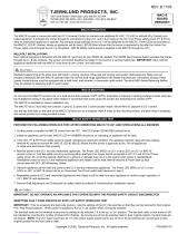
1.Disconnect power supply before making wiring connections to prevent electrical shock and equipment damage.
2. All wiring must comply with applicable codes and ordinances.
3. When wiring is completed, check all components by running system through its entire heating cycle.
4. Check vent pipe system for leakage. All vent system leaks must be sealed prior to the installation of the Draft Inducer.
5. Flue gas temperature must not exceed 575o F at Draft Inducer inlet.
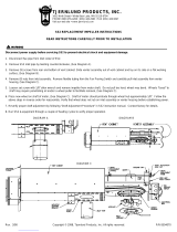
1. Loosen set screw on Draft Inducer wheel hub.
2.Remove nuts which attach motor mount to housing. Remove motor/mount
assembly and remove defective motor. NOTE: USE CARE SO
FASTENERS ARE NOT LOST.
3. To ensure proper performance and extended bearing life of the motor, inspect
wheel and clean if necessary. Refer to the installation instructions of your unit
for proper maintenance procedures.
4. Position new motor onto motor mount. Firmly fasten motor to motor mount
using proper spacers, washers and nuts removed in step 2. Insert motor
shaft into Draft Inducer wheel and attach motor/mount assembly to housing
with nuts removed in step 2.
5. Tighten Draft Inducer wheel set screw onto flat of motor shaft. Spin the wheel
by hand to ensure proper alignment and equal blade clearance on both
housing sides.
6. Wire Draft Inducer according to appropriate diagram on page 3. If appropriate
circuit does not appear, consult Tjernlund Products, Inc. at 800-255-4208.
UNIT MUST BE GROUNDED! All wiring must be done in accordance with the
NEC and applicable codes. The wiring from the appliance should be protected
by overcurrent protection(fuses or circuit breakers) rated 15 amperes or less,
as applicable for 14 AWG conductors. EXTREME CAUTION MUST BE
EXERCISED TO ENSURE THAT WIRING DOES NOT COME INTO
CONTACTWITH ANY HEAT SOURCE.
7. Check heater and Draft Inducer operation. Vari-Draft control on Draft Inducer
should be adjusted so that there is no spillage at draft diverter,hood or barometric.
MODELS D3 AND AD-1 MOTOR REPLACEMENT (DIAGRAM A)
MODEL 950-3022 REPLACEMENT MOTOR KIT
MODELS
AD-1
D-3
IN-FORCER PAI-1 & 2 SERIES WITH DATE CODES AFTER “9704” (DIAGRAM B)
1. Remove (6) screws from bottom front and sides of IN-FORCER while holding blower assembly firmly.
2. Carefully slide blower assembly down until stops hold blower unit in place.
3. Loosen set screw on wheel hub.
4.Remove nuts which attach motor mount to housing. Remove motor/mount assembly and remove defective motor. NOTE: USE CARE SO
FASTENERS ARE NOT LOST.
5. Position new motor onto motor mount. Firmly fasten motor to motor mount using proper spacers, washers and nuts removed in step 4.
Insert motor shaft into IN-FORCER wheel and attach motor/mount assembly to housing with nuts removed in step 4.
6. Secure IN-FORCER wheel by tightening set screw onto flat of motor shaft. Spin the wheel by hand to ensure proper alignment and equal
wheel clearance on both housing sides.
7. Slide blower assembly back into housing and replace (6) screws removed in step 1.
8. Wire new motor according to appropriate IN-FORCER factory wiring diagram and run IN-FORCER and heating equipment through a couple
of cycles to verify proper operation.
DIAGRAM A
TJERNLUND PRODUCTS, INC.
1601 Ninth Street • White Bear Lake, MN 55110-6794
PHONE (800) 255-4208 • (651) 426-2993 • FAX (651) 426-9547
Visit our web site • www.tjernlund.com

1. Remove (10) screws from top and side of
IN-FORCER. Loosen and remove nut inside
the electrical box while holding blower
assembly firmly.
2. Cut crimped connectors on motor leads.
3. Carefully remove the bottom of IN-FORCER
to see housing and motor assembly.
4. Loosen set screw on wheel hub.
5.Remove nuts which attach motor mount to
housing. Remove motor/mount assembly
and remove defective motor. NOTE: SAVE
MOTOR STUD SPACERS THAT ATTACH
TO ELECTRICAL BOX.
6. Position new motor onto motor mount. Firmly
fasten motor to motor mount with proper
spacers, washers and nuts removed in
step 5. Replace spacers on motor stud that
attaches to electrical box.
7. Insert motor shaft into IN-FORCER wheel and
attach motor/mount assembly to housing with
nuts removed in step 5.
8. Secure wheel by tightening set screw onto
motor shaft. Spin the wheel by hand to
ensure proper alignment and equal
wheel clearance on both housing sides.
IN-FORCER PAI-1 & 2 SERIES WITH DATE CODES PRIOR TO “9705” (DIAGRAM C)
IN-FORCER PAI-T SERIES FACTORY WIRING
DIAGRAM B
DIAGRAM C
9. Replace (10) screws removed in step 1. for IN-FORCER casing and replace motor stud nut.
10. Wire new motor according to appropriate IN-FORCER factory wiring diagram and run
IN-FORCER and heating equipment through a couple of cycles to verify proper operation.

REV. 1 5/98 © 1998 TJERNLUND PRODUCTS, INC. ALL RIGHTS RESERVED. P/N 8504066
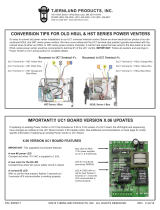
DRAFT INDUCER GAS WIRING TO ANY APPLIANCE EQUIPPED WITH 24V CONTROLS
NO POST-PURGE RELAY/TIMER ON DRAFT INDUCER
COMPONENTS NEEDED:
(1) DRAFT INDUCER
(1) PS1505 FAN PROVER
(1) 24/115V RELAY
USE 950-1040 FOR MODELS DJ3 & D3
DRAFT INDUCER CONNECTED TO OIL BURNER WITH R8184G CONTROLS
COMPONENTS NEEDED:
(1) DRAFT INDUCER
(1) PS1505 FAN PROVER
(1) 950-1067 RELAY/TIMER
MAXIMUM AMP LOAD IS
4.4 AMPS
IN-FORCER PAI-O SERIES FACTORY WIRING IN-FORCER PAI-G SERIES FACTORY WIRING
/