Page is loading ...

INSTALLATION MANUAL
AUSTRALIAN
DISPENSER UPGRADE
©2018 Triton Systems of Delaware, LLC. All Rights Reserved. ATMGurus®, the ATMGurus logo and tag-
line, Triton®, and the Triton logo are all registered trademarks of Triton Systems of Delaware, LLC. e third
party trademarks that may be identied herein are the trademark of their respective owners. Triton disclaims any
aliation, connection, or association between its products and services, and those of the respective trademark
owners, or any sponsorship or approval of its products and services by such trademark owners.
TDN 07103-00300 Rev B

Triton Systems ©
2
October 30, 2018 Add TDM guide rail settings for polymer notes ECO 1032221
November 26, 2018 Add MiniMech upgrade kit
Contact Information
Triton©
21405 B Street
Long Beach, MS 39560 USA
1 (877) 787-4866
1 (228) 575-3100
(228)575-3101 (fax)
www.atmgurus.com
Manufacturer warrants that the products delivered to a distributor will perform in accordance with the Manufac-
turer’s published specications for thirteen months from date of shipment from Long Beach, MS. Manufacturer’s
warranty shall not apply to any damage resulting from abuse, negligence or accident, or to any loss or damage to
the product(s) while in transit. Written notice and explanation of circumstances surrounding any claims that the
goods have proved defective in material or workmanship shall be given promptly from the distributor to the man-
ufacturer. No claim may be made, or action brought, by or through a distributor aer the expiration of 14 months
following any alleged breach of warranty.
Distributor’s sole and exclusive remedy in the event of defect is expressly limited to the replacement or correction
of such defective parts by manufacturer at its election and sole expense, except there shall be no obligation to re-
place or repair items which, by their nature, are expendable.
ese terms and conditions shall be governed by and construed in accordance with the provisions of the Uniform
Commercial Code as adopted by the State of Mississippi.
For detailed warranty information by unit, Soware End-User Agreement, access to ADA compliance statement,
ANSI statement of compliance, ISO 9001 compliance certicate, PCI v3 EPP certications, card reader TQM cer-
tications, EMV certications and more, please visit www.tritonatm.com.
is installation guide provides information, methods, and easy-to-follow instructions for installation of rm-
ware and various dispenser upgrades.

Triton Systems ©
3
..................................................................................................................
.........................................................................................................
..................................................................................................................................
...............................................................................................................
- ................................................................................................................
......................................................................................
.................................................
............................................................................................
.................................................................................
- ................................................................................................................
.............................................................................................
...............................................
.............................................................................................
.................................................................................
- ............................................................................................................
.................................................................................
- ..........................................................................................................
...............................................................................
- ..................................................................................................................
.......................................................................................
........................................................................................................
...................................................
....................................................................................
................................................................................
- .......................................................................................................
.........................................................................................

Triton Systems ©
4
Required Tools No. 2 Phillips screwdriver
Snips
Kit 41017-00006 HCDU Upgrade Kit
Part # Description Qty
1 Double detect emitter board 1
2 Double detect receiver board 1
3 Cable harness 1
**Note**
09120-00923 Serial Communication Cable and 06300-00007 Firmware Loader are necessary to complete the
rmware upgrade.
1
2
3

Triton Systems ©
5
**Note**
Service technician will need a rmware loader comloc and serial communication cable to complete this upgrade.
1. Perform a proper shutdown of ATM via Management Functions > System Parameters > Shut Down the Termi-
nal.
2. When prompted, place the power switch on the power supply to the o (O) position.
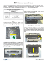
3. Access the vault.
4. Pull dispenser out to fully extended position.
5. Unplug dispenser power cable and communications cable. Detach ground wire if necessary and remove ca-
bles from cable clips, if necessary.
6. Grasp green handles on each side of dispenser and li straight up and o rails.
7. Place dispenser on at work surface or table.
8. Remove handles, then loosen the four screws securing the cover over the dispenser main board.
9. Slide cover up until notches clear the screws, then li away.

Triton Systems ©
6
10. Unplug red/blue wire on cable harness from double detect emitter board.
11. Remove emitter board by removing screw and routing board out through square opening. Retain screw for
reinstallation.
12. Remove new emitter board (with clear LEDs) from upgrade kit. Slide emitter board into square opening and
align notch into top hole.
13. Secure emitter board with screw removed in step 11.

Triton Systems ©
7
14. Unplug the yellow/black wire on cable harness from double detect receiver board.
15. Remove receiver board (with black sensors) by removing screw and routing board out through square open-
ing. Retain screw for reinstallation.
16. Remove new receiver board (with black sensors) from upgrade kit. Slide receiver board into square opening
and align notch into bottom hole.
17. Secure receiver board with screw removed in step 15.

Triton Systems ©
8
18. Snip TY wraps securing cable harness to dispenser. Gently pull wiring harness from behind metal plates and
snip any TY wraps securing cable harness to other wires.
19. Unplug cable harness from dispenser main board at JP8.
20. Remove new cable harness from upgrade kit and plug into dispenser main board. You may use the old cable
harness as a guide. Connect rest of cable harness and secure with TY Wraps.
21. Reconnect the dispenser power cable to dispenser and available outlet or power supply.
A
B
C
D
E
F
G
H
Dispenser Main Board
JP8
Main Motor Encoder
(ENC)
New Emitter Sensor
B/R/R
1st CST Exit, Right (CTR)
B/R
Reject Gate (GAT)
B/R
Reject Gate (GAT)
BLK/Y
New Double Detect
Sensor Y/Y/BLK
H
B
C
E
A
F
D
G
1st CST Exit,
Right (CTR)
Y/BLK

Triton Systems ©
9
A serial communication cable (p/n 09120-00923) is required to download the rmware from the PC to the serial
CDU dispenser. If your PC does not have a serial port, you will also require a USB-to-serial adapter (p/n 01260-
00019).
**Note**
Screen shots are indicative of what should be seen during the load process. Firmware versions and actual screens
may vary.
22. Unplug the unit data cable from the dispenser, if necessary. Attach the serial communications cable from
laptop/desktop computer to the dispenser.
23. Switch all four dip switches on the dispenser to the OFF position. If the dispenser is powered on when the
dip switches are ipped, press black reset button near the dip switches to set the dispenser into download
mode.
Reset
Button

Triton Systems ©
10
24. Insert comloc into the USB slot on PC.
25. Run the utility loader by clicking on Start > All Programs > Triton > CDU Load.
26. In the drop down box, choose the COM port where the dispenser cable is plugged in.
**Note**
Screen shots are for example purposes only. Firmware version may dier.

Triton Systems ©
11
If you are using a USB-to-serial adapter, you can determine the COM port to use by going to Control Panel >
Device Manager in Windows. Locate the USB-to-serial device name under ports. e COM port associated with
this device is shown.
27. Choose “scdu(0910XX).bin” for a SCDU Dispenser or “hcdu(0b12XX).bin” for an HCDU dispenser. e
green progress bar will advance as the load proceeds.
28. Click Start. e program will load onto dispenser. e status bar along the bottom will ll up with green as

Triton Systems ©
12
the program runs.
29. When the program has loaded completely, the status bar at the bottom will state Success. e dispenser can
now be disconnected safely. Unplug the download data cable from the dispenser.

Triton Systems ©
13
30. Flip dip switches 1, 3, and 4 to the ON position. Press the reset button below the switches to put the dispens-
er into dispense mode.
31. Replace cover over dispenser main board, and tighten the four screws to secure, then install handles.
32. Remove cassettes from dispenser.
33. If using old cassettes, adjust cassette width rails where necessary. Rail location is dependent on denomina-
tion of new Australian polymer bank note being loaded into cassette. If using new Australian polymer-ready
cassette, verify width rails are in correct location.
Bank Note Width Directions
AUD $5 145 mm Loosen two screws on each width rail.
Slide rails to center position.
Tighten two screws on each width rail to secure.
AUD $10 TBA TBA
AUD $20 TBA TBA
AUD $50 TBA TBA
AUD $100 TBA TBA
34. Load or replenish bank notes in cassettes. Close and lock cassettes.
35. Install cassettes in dispenser.
36. Grasp green handles on either side of dispenser and lower dispenser onto slide rails. Ensure dispenser seats
onto round tabs on the slide rails.

Triton Systems ©
14
37. Reconnect dispenser power cable and communications cable. Reattach ground wire if necessary.
38. If the dispenser is installed in an ATM at the time of upgrade, restart the unit.
39. Once the load is complete, review the ATM conguration summary. Verify the dispenser rmware.
Dispenser
Device ID: Hantle MCDU-H1
Firmware Ver: MCDU-H1-U2-0B.12.69
Device Status: 0 (Success)
Number of Cassettes: 3
Cassette A
Multiple Amount: $10.00
Document Type: Cash
Cassette In Service: Yes
Device ID: Hantle MCDU-H1
Firmware Ver: MCDU-H1-U2-0B.12.69
Reject Sts: Success (0)
Security Module
Serial Number:
Security Module Version: SM-
01.01.011
Security Module Keys Synchronized:
Yes
40. Push levers on slide rail, one on each side of dispenser, to slide dispenser into vault.
41. Close vault door.

Triton Systems ©
15
42. e rmware loader has a set number of downloads. To verify the number of downloads le on your system,
insert the comloc into the computer, open the application, then click on About.
43. A window will appear that shows the application version for information. e number of remaining down-
loads on the systems is shown here.
44. To purchase additional downloads, contact Triton Technical Support at 1-866-787-4866 option 4, or techsup-

Triton Systems ©
16
Required Tools No. 2 phillips screwdriver
Kit 41017-00005 SCDU Upgrade Kit
Part # Description Qty
1 Count sensor emitter board 1
2 Count sensor receiver board 1
3 Cable 1
4 Spacers 1
**Note**
09120-00923 Serial Communication Cable and 06300-00007 Firmware Loader are necessary to complete the
rmware upgrade.
2
1
4
3
SCDU II and SCDU III dispensers require a second sensor channel connector on the dispenser main board to
function with the New Australian Polymer Upgrade Kit. If dispenser main board does not have the second con-
nector in the top le corner, a new dispenser main board must be purchased in addition to the upgrade kit.

Triton Systems ©
17
A serial communication cable (p/n 09120-00923) is required to download the rmware from the PC to the serial
CDU dispenser. If your PC does not have a serial port, you will also require a USB-to-serial adapter. Both parts
are readily available at local electronics stores.
**Note**
Screen shots are indicative of what should be seen during the load process. Firmware versions and actual screens
may vary.
1. Perform a proper shutdown of the ATM via Management Functions > System Parameters > Shut Down the
Terminal.
2. When prompted, place the power switch on the power supply to the o (O) position.
3. Access the vault.
4. Unplug dispenser power cable and communications cable.
5. Remove four screws securing dispenser to tray within vault. Retain for reinstallation.
6. Remove dispenser from vault.
7. Place dispenser on a at work surface or table if removed from unit.
8. Loosen the four screws securing the cover over the dispenser main board.
9. Slide cover up until notches clear the screws, then li away.

Triton Systems ©
18
10. Unplug the red/blue wire on cable harness from the count sensor emitter board.
11. Remove emitter board by removing screw and routing board out through opening. Retain screw for reinstal-
lation.
12. Remove new emitter board from upgrade kit. Slide emitter board into opening and align notch into right-
side hole.
13. Secure emitter board with screw removed in step 11.
14. Unplug the black/yellow wire on cable harness from the count sensor receiver board.
15. Remove receiver board by removing screw and routing board out through opening. Retain screw for reinstal-
lation.
receiver
emitter
**Note**
e rubber cover on the sensor closest to the receiver board screw may need to be removed for receiver board
installation. Replace rubber cover aer installation.
16. Remove new receiver board from upgrade kit. Slide receiver board into opening and align notch into le side
hole.
17. Secure receiver board with screw removed in step 15.
18. Unplug cable harness from the dispenser main board. Unclip from cable clip, if necessary.
19. Remove new cable harness from the upgrade kit.
20. Plug black/yellow wire (A) from cable harness into receiver board and yellow wire (A) into dispenser main
board, as shown.
21. Plug the blue/red wire (B) from cable harness into emitter board and dispenser main board, as shown.
A
A
B
B
22. Reconnect the dispenser power cable to dispenser and available outlet or power supply.

Triton Systems ©
19
A serial communication cable (p/n 09120-00923) is required to download the rmware from the PC to the serial
CDU dispenser. If your PC does not have a serial port, you will also require a USB-to-serial adapter (p/n 01260-
00019).
**Note**
Screen shots are indicative of what should be seen during the load process. Firmware versions and actual screens
may vary.
23. Unplug the unit data cable from the dispenser if not already done. Attach the data cable from laptop/desktop
computer to the dispenser.
24. Switch all four dip switches on the dispenser to the OFF position. If the dispenser is powered on when the
dip switches are ipped, press black reset button near the dip switches to set the dispenser into download
mode.
Reset
Button

Triton Systems ©
20
25. Insert comloc into the USB slot on PC.
26. Run the utility loader by clicking on Start > All Programs > Triton > CDU Load.
27. In the drop down box, choose the COM port where the dispenser cable is plugged in.
**Note**
Screen shots are for example purposes only. Firmware version may dier.
/