Page is loading ...

SK300-ENG/071019
Steam Humidifier
SK300 series
Installation instruction & user
manual
READ AND SAVE THESE INSTRUCTIONS

SK300 Humidifier
Foreword
i
Foreword
1. These installation instructions and operation manual have been developed to facilitate the installation and the
operation of the SK300 series steam humidifier.
The strict application of these instructions will ensure the conformity of your installation and operation as per
manufacturer's recommendations.
2. The application of these instructions is one of the conditions for the application of the warranty.
3. The application of these instructions does not ensure at any time conformity to procedures, regulation or local
codes, regarding electric installation and connection to local water supply.
4. This product has been declared to conform to applicable Canadian and American safety standards and
directives and bear the CSA (c) & (us) mark. The certificate of conformity CSA is available upon request to the
manufacturer.
5. © 2007: All right reserved, this document cannot be reproduced totally or partially by any mean whether,
electronic, mechanical, photocopy, recording or other, without prior written authorization of National
Environmental Products Ltd.
Manufacturer Presentation
National Environmental Products Ltd. (NEP) is the owner of the brand Neptronic®.
NEP develops, manufactures and services a complete line of:
• Steam humidifiers,
• Humidistat among the most precise and the most reliable on the market,
• Actuators to regulate air damper or valves,
• Electric heaters,
• Thermostats and other control peripherals used to control HVAC equipment.
For more information about our products, visit our web site at www.neptronic.com
Each Neptronic® product benefits from over 25 years of experience of our qualified staff.
From the inspiration to realization, innovation has been the standard in design. As the result of this dedication, NEP Ltd.
owns several patents, notably the ENERDRIVE system and the AFEC system.
Manufacturing is conducted on the premises of our modern 80,000 sq.ft. (7 000m2) facility in Montreal, Canada.
Our quality system is built on the ISO 9001 model.
Our vision '' Customer for Life'' is realized by listening to their needs and by supplying them with products, which
exceed their expectations in quality, functionality and durability.
National Environmental Products Ltd.
Tel. (Toll free): 1 800 361-2308
Tel.: (1) (514) 333-1433
Fax: (1) (514) 333-3163
Fax Customer service: (514) 333-1091
Business hours: from Monday to Friday, 8:00am to 5:00pm (Eastern time)

SK300 Humidifier
Table of contents
1
Table of contents
Foreword and Manufacturer Presentation.……………….…….……………………………………………………………….i
1. Presentation..............................................................................................................................................................2
1.1. Overview .................................................................................................................................................................................2
1.2. Definition .................................................................................................................................................................................3
2. Characteristics .........................................................................................................................................................4
2.1. Dimensions & weight...............................................................................................................................................................4
2.2. Output and power consumption...............................................................................................................................................5
3. Mechanical installation............................................................................................................................................6
3.1. General recommendations......................................................................................................................................................6
3.2. Positioning...............................................................................................................................................................................6
3.3. Wall mounting..........................................................................................................................................................................6
4. Steam dispersion system selection and positioning...........................................................................................7
4.1. Steam dispersion system selection.........................................................................................................................................7
4.2. Positionning of S.A.M or S.A.M.E2..........................................................................................................................................9
5. Steam output connection......................................................................................................................................12
5.1. Typical installation.................................................................................................................................................................12
5.2. General recommendations....................................................................................................................................................12
5.3. Installation of “S” traps on the steam line ..............................................................................................................................12
5.4. Position of steam output........................................................................................................................................................13
5.5. Installation of humidifier with Space Distribution Unit (SDU).................................................................................................14
6. Plumbing connection.............................................................................................................................................15
6.1. Water supply .........................................................................................................................................................................15
6.2 Drain connection ...................................................................................................................................................................16
7. Power supply connections....................................................................................................................................16
8. Low voltage control connections.........................................................................................................................17
8.1. ''ON/OFF'' Humidifier.............................................................................................................................................................17
8.2. Modulating Humidifier............................................................................................................................................................17
8.3. Common Alarm Connections.................................................................................................................................................21
8.4. Controls Placement (steam dispersed into a duct or AHU) ...................................................................................................21
9. Front panel display features.................................................................................................................................22
9.1. Description display modes.....................................................................................................................................................23
9.2. Programming.........................................................................................................................................................................25
10. Control p.c. board..................................................................................................................................................26
10.1. Main p.c. board......................................................................................................................................................................26
10.2. Modulating p.c. board............................................................................................................................................................26
11. Start up procedure.................................................................................................................................................27
12. Service.....................................................................................................................................................................28
12.1. General .................................................................................................................................................................................28
12.2. Evaporation chamber cleaning..............................................................................................................................................28
13. Exploded view & Bill of Material...........................................................................................................................31
13.1. Exploded view.......................................................................................................................................................................31
13.2. Bill of material........................................................................................................................................................................32
14. Trouble shouting guide.........................................................................................................................................34
General condition of Sale & Warranty...……………………………………………………….……………………………….37

SK300 Humidifier
User Manual
2
1. Presentation
Thank you to have chosen one of the Neptronic® products. You have purchased the best and the most robust
humidifier for its category.
1.1. Overview
1.1.1. List of accessories supplied
• 2 sets of keys.
• 2 adjustable collars for the connection of the steam hose for each steam output.
• 1 female fitting ¾ hydraulic for the drain output of the evaporation chamber.
• 1 female fitting ½ hydraulic for the drain output of the drip pan.
• 1 Installation instruction and operation manual.
1.1.2. Overview of the Humidifier
Access door to
mechanical
compartment
Heater element
connector
Heater element
Level sensor
chamber
Water supply valve
Electrical
compartment
Evaporation
chamber
Drain valve
Evaporation
chamber
Control panel
(Illus. 1)

SK300 Humidifier
User Manual
3
1.1.3. Options avalaible
The following options are available when purchasing a SK300 humidifier:
• Modulating control humidifier – suffix M (i.e. SK320M)
• Humidifier for system supplied with Deionised water or Reverse Osmosis water, dissolved solids
more than 1 ppm (SF DI-APPLICATION)
• Humidifier for system supplied with Deionised water or Reverse Osmosis water, dissolved solids
more than 0.028 ppm (SF ULTRAPURE-DI)
• Internal Drain Cooler (IDC) to temper the drain water to a temperature below 140°F (60°C) (SF
DRAINCOOL-INT)
• Space Distribution Unit mounted on humidifier (SDU) or remote installation (SDU-REM)
• Network communication system, BACnet – suffix B (i.e. SK320M-600-3B)
• Stainless steel humidifier cabinet – suffix P (i.e. SK320M-600-3P)
• Dry contact to activate an external fan relay on a call for humidity (SF SK300FANRELAY)
• Fill and drain trap assembly (see section 13. Exploded view item L) without copper elbows for
easy access cleaning – suffix N (i.e. SW TRAPSMA-N)
• Fill and drain trap assembly (see section 13. Exploded view item L) with check valve for high
static pressure inside the duct/AHU or multiple humidifiers using a single Multi-Steam – suffix C
(i.e. SW TRAPSMA-C)
• Fill and drain trap assembly (see section 13. Exploded view item L) with check valve and an
external actuated drain valve for hard water condition – suffix F (i.e. SW TRAPSMA-F)
1.2. Definition
1.2.1. Evaporation chamber
Assembly including the metal cylinder and a cover equipped with one or several heater elements. It is
the heart of the humidifier, which produce steam.
1.2.2. SDU (Space Distribution Unit)
Integrated steam distribution unit, optional on certain humidifiers.
1.2.3. Multi-Steam system
Custom made system of steam distribution. This system is designed to allow very short absorption
distances (less than 3 feet or 900mm).
1.2.4. S.A.M. (Steam Absorption Manifold)
Steam manifold adapted to air duct size to allow steam absorption in relatively short distance (less than
5 feet or 1500mm).
1.2.5. S.A.M.E2 (Steam Absorption Manifold with 2 Eyelets)
Steam manifold with two eyelets adapted to application with restricted air duct dimensions to allow
steam absorption in relatively short distance (less than 5 feet or 1500mm).

SK300 Humidifier
User Manual
4
2. Characteristics
C
B
AE
D
Steam Humidifier
SDU
Space Distribution
Unit (option)
(Illus. 2)
2.1. Dimensions & weight
Dimensions of the cabinet inch (mm)
Weight lb (kg)
Model A B C D E Empty Full of
water
Option SDU
Model
Weight
lb (kg)
SK302
SK304
SK306
23 ½
(597)
18 ½
(470)
11 ½
(292)
5 ⅝
(140)
29 ⅛
(737)
44
(20)
57
(26) SDU-1
20 (9)
SK310
SK314
28 ½
(724)
21
(533)
12 ½
(318)
6 ⅝
(165)
35 ⅛
(890)
66
(30)
115
(52) SDU-2
25 (11)
SK320
SK330
28 ½
(724)
21
(533)
12 ½
(318)
12 ⅞
(324)
41 ⅜
(1048)
66
(30)
115
(52) SDU-3
45 (20)
SK340
SK360
31 ¼
(794)
32
(813)
12 ½
(318) - -
110
(50)
205
(93) -

SK300 Humidifier
User Manual
5
2.2. Output and power consumption
Steam Consumption
Steam Output
Amperage (A)
Model Capacity
lb/hr (kg/hr) Power
(KW) 240/1 208/1 208/3 480/1 480/3 600/1 600/3 Qty Diameter
inch (mm)
SK302 6
(2.7) 2 8.5 10 - 4.5 - 3.5 - 1 1 ⅜
(35)
SK304 12
(5.5) 4 17 19 11.5 8.5 5 7 4 1 1 ⅜
(35)
SK306 18
(8) 6 26 30 16.5 13 7.2 10.5 6 1 1 ⅜
(35)
SK310 30
(14) 10 - - 28 - 12 - 10 1 1 ⅜
(35)
SK314 40
(19) 13.5 - - 38 - 16.5 - 13.5 1 1 ⅜
(35)
SK320 60
(28) 20 - - 57 - 25 - 20 2 1 ⅜
(35)
SK330 90
(41) 30 - - - - 36 - 30 2 1 ⅜
(35)
SK340 120
(56) 40 - - 120 - 50 - 40 2 2 ⅛
(54)
SK360 180
(82) 60 - - - - 72 - 60 3 2 ⅛
(54)
Option:
• On modulating humidifier, the maximum steam output can be programmed with the function ''LOCK ON'' in
Program mode.
WARNING (MODULATING HUMIDIFIER): MAXIMUM POWER OF THE ELECTRICAL INSTALLATION SHOULD BE IN
ACCORDANCE WITH THE ABOVE TABLE, DO NOT TAKE ACCOUNT A POSSIBLE REDUCTION OF STEAM
OUTPUT, DUE TO MODULATION.

SK300 Humidifier
User Manual
6
3. Mechanical installation
3.1. General recommendations
• CAUTION: RISK OF ELECTRIC SHOCK. DISCONNECT THE APPLIANCE FROM THE ELECTRIC SUPPLY
BEFORE TO PROCEED TO INSTALLATION.
• Location: Plan a location easy to access in order to permit an easy inspection and servicing of the humidifier.
Do not install humidifier where failure of the appliance could cause damage to the building structure or to costly
equipment.
This location should be well ventilated; the ambient temperature should not exceed 85°F (30°C).
• The maximum distance between the humidifier and the ventilation duct should not exceed 16 feet (5 meters)
(maximum length of the steam hose).
(0,60 m)
(0,25 m) (1 to 1,2 m)
10'’
24'’
39 to 48'’
Positioning (Illus. 3)
3.2. Positioning
• The front panel and the right side (electrical compartment) should be
accessible in order to permit the servicing.
Leave a clearance of at least 48” (1,25m) to the front panel and 24”
(0,6m) to the right side.
• The humidifier should be mounted at a minimum of 39” (1m) to 48”
(1,2m) above floor level.
Leave a clearance of at least 10” (0,25m) under the humidifier for
installation of water supply, drain piping and electrical connections.
3.3. Wall mounting
• Use the keyholes located on the back panel of the humidifier.
• Before to proceed to the wall mounting, take off the Evaporation
chamber sub assembly (see section 12, Servicing).
• Check the solidity of the chosen support or wall (bricks, concrete,
stud partition wall, etc) on which the humidifier will be mounted.
• Drill holes for the upper anchors (holes with eyelet) into the support
or wall as per dimensions specified in the table (illus.4).
The holes dimensions (diameter and depth) should by in accordance
with the recommendations of the chosen anchors.
• Install then bolt anchors, if required.
• Screw-on the 2 or 3 upper screws (holes with eyelet) of a minimum
diameter of #10 (6mm) (screws are not supplied).
Leave a clearance between head screws and wall in order to permit
the mounting of the humidifier.
• Use the keyholes located on the back panel of the humidifier.
• Hang on the humidifier to the 2 or 3 screws; it is preferable let the
front door open during this operation.
According to the size and weight of the humidifier, you may need the
help of a second person to assist you.
• When the humidifier is positioned on the upper screws, tighten the
screws to secure the humidifier.
• If applicable, install and secure lower screws.
Front view (Illus. 4)
Dimensions inches (mm)
Model A B C D E F G
SK302, SK304, SK306 - 8 (202) 5
3/16 (165) 19 ¾ (516) - - -
SK310, SK314,
SK320, SK330 - 10 (254) 8 (203) 24 ⅝ (625) 11 (276) 8 (203) 10 (254)
SK340, SK360 4 (100) 12 (303) 10 ½ (265) 27 ½ (698) 11 (276) 18 ⅜ (468) -

SK300 Humidifier
User Manual
7
4. Steam dispersion system selection and positioning
4.1. Steam dispersion system selection
In order to prevent the accumulation of condensation in air ducts, NEP has designed 4 basic configurations of
steam distribution to provide the client with the most economical solution for any particular application.
4.1.1. S.A.M. (steam absorption manifold) Horizontal duct
air
(Illus. 5)
The SAM is to be installed where
absorption distances are short, less
than 5 feet (1500mm), and/or low
duct temperatures are in effect.
4.1.2. S.A.M.E2 (steam absorption manifold) Horizontal duct
900
air
(Illus. 6)
The SAME2 is to be installed
where absorption distances are
short, less than 5 feet (1500mm)
and/or low duct temperatures are
in effect. SAME2 are used in
applications with restricted duct
dimensions.

SK300 Humidifier
User Manual
8
4.1.3. S.A.M. or S.A.M.E2 (steam absorption manifold) Vertical duct
S.A.M.
S.A.M.E2.
45°
45° 45°
air
air
(Illus. 7)
SAM or SAME2 for vertical ducts
are used where the absorption
distances are normal and the
client requires an economical as
well as an efficient solution.
4.1.4. Multi-Steam system
air
(Illus.8)
The Multi-Steam system is to be
installed in critical locations in air
handling systems, particularly
where absorption distances are
very short, less than 3 feet
(900mm), or low air duct
temperatures are in effect.
The Multi-Steam is custom made
to the dimensions of duct or AHU.
Instructions to install Multi-Steam
system are described in a specific
installation instructions manual
enclosed with the Multi-Steam
system.

SK300 Humidifier
User Manual
9
4.2. Positionning of S.A.M or S.A.M.E2
4.2.1. Duct mounting
Steam manifold should be mounted and
secured through the side of the air
handling unit or duct. Provision should be
made for safe accessibility, ideally with an
observation light and window.
Check that the construction of the duct
wall is suitable enough to support the
steam pipe for the duration of the
installation life.
Dimension of hole size in the duct must be
as per table below:
Steam manifold Ø Hole size ØA
1 ⅜’’ (35mm) 2’’ (51mm)
2 ⅛’’ (51mm) 3’’ (78mm)
5'’
(120mm)
5'’
(120mm)
ØA
(Illus. 9)
WARNING: Risk of condensing. Ensure
that the minimum distance of the end of
the manifold is at least 4’’ (102mm) from
the top of the duct.
4'’ minimum
(102mm)
Minimum distance (Illus. 10)
4.2.2. Recommendations for SAM distribution pipes
Maximum
Capacity Outlet Distribution pipes
Diameter Minimum
length Maximum
length
Maximum
static pressure
Model (lb/hr) (kg/hr) Qty In
(mm) in.
(mm) in.
(mm) in. of
water (Pa)
SK302 6 2.7
SK304 12 5.5
SK306 18 8
12
(300)
24
(600)
SK310 30 14
SK314 40 19
1
SK320 60 28
24
(600)
48
(1200)
SK330 90 41
1 ⅜
(35)
SK340 120 56
2
SK360 180 82 3
2 ⅛
(51)
32
(750)
64
(1500)
5 1245
Note: For higher static pressure, please contact the manufacturer.

SK300 Humidifier
User Manual
10
4.2.3. Placement of steam pipe in horizontal duct
1 ⅜’’ (35mm) diameter pipe
H
10'’ minimum
(250mm)
1/3 H
air
1 pipe (Illus. 11)
air
H
10'’ minimum
(250mm)
3'’ minimum
(80mm)
8'’
(200mm)
6'’ minimum
(150mm)
2 pipes (Illus. 12)
2 ⅛’’ (51mm) diameter pipe
H
24'’ minimum
(600mm)
1/5 H
2/5 H
8'’
(200mm)
air
2 pipes (Illus. 13)
H
36'’ minimum
(900mm)
1/6 H
1/2 H
1/3 H
10'’
(250mm)
10'’
(250mm)
air
3 pipes (Illus. 14)
Note: 2 ⅛’’ (51mm) steam pipe must be supported on the end by appropriate duct hanger or
strap (supplied by others).

SK300 Humidifier
User Manual
11
4.2.4. Placement of steam pipe in vertical duct
Eyelet orientation
air
3D view (Illus. 15)
air
45°
air
45°
S.A.M S.A.M.E2
(Illus. 16)
1 ⅜’’ (35mm) diameter pipe
W
10’’ minimum
(250mm)
1/2 W
1 pipe (Illus. 17)
W
24’’ minimum
(600mm)
1/2 W 1/4 W1/4 W
2 pipes (Illus. 18)
2 ⅛’’ (51mm) diameter pipe
W
24’’ minimum
(600mm)
1/2 W 1/4 W1/4 W
2 pipes (Illus. 19)
W
36’’ minimum
(900mm)
1/3 W 1/3 W
1/6 W 1/6 W
3 pipes (Illus. 20)

SK300 Humidifier
User Manual
12
5. Steam output connection
5.1. Typical installation
15 %
2
2
2
4
4
3
3
5
1
1
1
6
Humidifier
(Illus. 21)
5.2. General recommendations
Please follow these general rules of installation in order to avoid any static pressure inside distribution pipes
and into the humidifier evaporation chamber, and also to avoid any condensation accumulation.
a) The slope of the steam hose (rigid or flexible)
should not be less than 15% (7 horizontal length for
1 vertical length) in order to ensure continuous
drainage of condensation back to humidifier or to
steam trap.
b) Total length of the steam hose or rigid pipe should
not exceed 16feet (5 meters). Longer runs will result
in added condensation losses. Whenever possible,
use insulated copper piping. Flexible steam hose
should be used for short runs (up to 16ft or 5m) or for
interconnecting between the rigid pipe runs.
c) Whenever using rigid copper, these ones should
be insulated to diminish condensation build up. Incorrect installation
(Illus. 22)
5.3. Installation of “S” traps on the steam line
The lowest point of any steam hose or rigid pipe must be the humidifier. If necessary a steam separator
(S trap) should be installed higher than the static pressure of the system by at least 2” (51mm).
8"
15% 15%
Use "S" separator
when ceiling space is
limited and you need
to create 15% slopes
Steam outlet
(Illus. 23)
Use ‘’S’’ separator when
the steam distributor is
lower than the humidifier
steam outlet
8'’
(203mm)
15%
(Illus. 24)
1 Clamps
2 Flexible hose
3 Rigid copper pipe
4 Insulation
5 Steam distribution manifold
6 Duct

SK300 Humidifier
User Manual
13
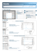
5.4. Position of steam output
Model Dimensions inches (mm)
Small
Cabinet I J
SK302
SK304
SK306
4 5/16
(110)
4 13/16
(122)
Medium
Cabinet K L M
SK310
SK314 - 4
(102)
5 5/8
(143)
SK320
SK330
5 9/32
(134)
4
(102)
5 5/8
(143)
Large
Cabinet N O P Q
SK340
SK360
7
(179)
7
(179)
5 3/16
(132)
5 11/16
(144)
I
J
L
M
Small Cabinet
(SK302-304-306)
Medium Cabinet
(SK310-314)
Medium Cabinet
(SK320-330)
L
MK
Large Cabinet
(SK340)
Large Cabinet
(SK360)
P
QON
P
QON
(Illus. 25)

SK300 Humidifier
User Manual
14
5.5. Installation of humidifier with Space Distribution Unit (SDU)
18'’
(0,45 m)
78'’
(2 m)
Without
additional
ventilation
54'’ (1,35 m)
SDU mounted on humidifier (Illus. 26)
• The SDU should be installed in an
environment where the air is relatively
clean. This will avoid the blower from
getting clough with dust.
• The humidifier should be mounted such
that the SDU fan section is at least 78”
(2m) above the floor.
• A minimum clearance of 18” (0.45m) from
the ceiling should be allocated to avoid
ceiling and wall condensation.
If additional ventilation is not present, the
fan should have a clearance from the
ceiling of at least 54” (1.35m). Proper
ventilation must be observed to avoid
ceiling and wall condensation.
SDU remote installation:
• The SDU can be in a different location
from the humidifier (remote SDU). Please
follow the piping recommendations
(section 5.2).
• Mount the SDU to the wall on brackets
(not supplied), do not drill mounting holes
thru the cabinet of the SDU.
• Connect the steam hose(s) to the bottom
inlet(s) of the SDU to the top of the steam
outlet(s) of the humidifier. Secure the
hose(s) with the supplied hose clamp.
• Connect the condensate hose to the
bottom of the SDU to an open drain.
• Connect the electrical wires from the SDU
to the top of the humidifier. Field wiring
must conform to local codes.
The fan of the SDU will operate for a period of
four minutes after steam production has
stopped to prevent condensation.
Avoid any obstruction of the ventilation
openings on top of the SDU.
Maintenance of the SDU:
• Clean the blower if there is an
accumulation of dust.
18'’
(0,45 m)
78'’
(2 m)
Field piping
(not supplied)
Without
additional
ventilation
54'’ (1,35 m)
4'’
(0.10m)
Field wiring
(by others)
2nd pipe
for SDU2 or SDU3
SDU remote installation (Illus. 27)

SK300 Humidifier
User Manual
15
6. Plumbing connection
The operation of SK300 series humidifier is independent of variable water conditions, with soft or hard water. Therefore,
for normal operation, no pre-treatment of water is necessary.
A
B
C
DE
Bottom view (Illus. 28)
Dimensions inches (mm)
Model A B C D E
SK302
SK304
SK306
6 ½
(165)
2
(51)
9 ⅛
(232)
4 ⅛
(105)
1 ¾
(44)
SK310
SK314
SK320
SK330
7 ¼
(184)
1 ¾
(44)
9 ¾
(248)
4 ⅛
(105)
1 ¾
(44)
SK340
SK360 7
(179)
1 ¾
(44)
9 ¾
(248)
4 ⅛
(105)
1 ¾
(44)
Open drain ''P'' Trap
Water line
3/8'' hydraulic pipe
Pan drain
1/2'' hydraulic pipe
Evaporation chamber drain
3/4'' hydraulic pipe
10'’ minimum
(254 mm)
(Illus. 29)
6.1. Water supply
• Water inlet specifications:
9 Inlet water pressure: 10 to 70 psig (0,7 to 4,8 bars)
9 Maximum temperature: 85°F (30°C) maximum
9 3/8'' standard copper water line connection
• A shut off valve (not supplied) should be installed in the water supply line to the humidifier, close to the
humidifier to facilitate servicing.
• It is recommended to install a standard water strainer in the water supply line.
Please follow the steps described below:
• Connect 3/8'' copper pipe to the bottom 3/8''
compression fitting (supplied).
• Finger tighten the swivel top 3/8'' fitting to the male
threaded part of the valve.
CAUTION: RISK OF DAMAGE TO THE VALVE.
DO NOT USE WRENCH TO TIGHEN SWIVEL.
Base plate of
humidifier
Male threaded part of
the valve
Fill valve
(Intern)
Swivel top
Compression
fitting
Water line 3/8'’ (10mm) pipe
(by others)
(Illus. 30)

SK300 Humidifier
User Manual
16
6.2. Drain connection
• Drain connection specification:
9 Evaporation chamber water drain temperature: 180°F (83°C).
9 Standard hydraulic fitting: 1 connector ¾ (evaporation chamber drain) and 1 connector ½ (Pan drain).
• 2 hydraulic threaded fitting located under the humidifier (see Illus. 29) must be connected to the drain pipe. We
recommend the use of standard copper hydraulic pipes ¾ and ½.
• Ensure that the drain pipe dimension is sufficient, especially if more than one humidifier is evacuating into the
same drain line.
7. Power supply connections
• CAUTION: RISK OF ELECTRIC CHOC. DISCONNECT THE HUMIDIFIER FROM THE ELECTRIC SUPPLY
BEFORE TO PROCEED TO THE CONNECTION.
• WARNING: RISK OF FIRE. Do not interchange the power terminal block designated L1, L2 and L3 with Low
voltage terminal block designated 1, 2 and 3.
• The wiring to the Humidifier should be done by a qualified electrician, and conforming to the procedure,
regulation and local codes.
• Use only coppers conductors.
• An external over current protection and disconnect circuit breaker should be installed on the supply adjacent to
the humidifier.
• A knock out (not supply) should be installed at the bottom of the electrical compartment of the humidifier for
strain relief of the supply cable.
• Ensure that the size of the wire conductors is appropriate for the current supplied.
• Ensure that each terminal connection is properly secured.
• The ground conductor should be equipped with ring terminal and should be connected directly to the electrical
panel on the indicated location.
1 Phase Connection
GND
L1 L2
PHASE 1
PHASE 2
(Illus. 31)
3 Phases Connection
L1 L2 L3
PHASE 1
PHASE 2
PHASE 3
GND
(Illus. 32)

SK300 Humidifier
User Manual
17
8. Low voltage control connections
8.1. ''ON/OFF'' Humidifier
5 Vdc
Low voltage control
terminal block
High voltage power
terminal block
12789
Humidistat
High
limit
Pressure
Differential
switch
5 Vdc
2
19
8
7
(Illus. 33)
8.2. Modulating Humidifier
8.2.1. Humidity control by humidistat (external mode)
Connection to HDM or HRM humidistat.
humidistat
com
24 VAC
%RH
MOD
Set point
Pressure Differential
switch
High limit humidistat
1
875
432F
69
or
Low voltage control
terminal block
High voltage power
terminal block
L1 L2 L3
F
5
4321
98
67
5 Vdc
(Illus. 34)

SK300 Humidifier
User Manual
18
8.2.2. Humidity control by humidifier (internal mode)
Humidity controlled by humidifier, using HRM-X or HDM-X as space sensor.
1
875
432F
69
1
3
2
COMMON
0-10 VDC OUTPUT
24 VAC OR VDC
HRM-X
or
HDM-X
SK300
To Term. #3
To Term. #F
To Term. #6
(Illus. 35)
VAV system with humidity controlled by humidifier, using HDM-X as Hi limit duct sensor and HRM-X or
HDM-X as space sensor.
1
875
432F
69
SK300
To Term. #3
To Term. #F
To Term. #4
1
3
2
COMMON
0-10 VDC OUTPUT
24 VAC OR VDC
HDM-X
1
3
2
COMMON
0-10 VDC OUTPUT
24 VAC OR VDC
HRM-X
or
HDM-X
To Term. #F
To Term. #3
To Term. #6
Note: when HDM-X is used as Hi limit
Duct sensor, control signal jumper
should be placed on 0-10 Vdc on
Modulating PCB (see section 8.2.4 of
installation instructions)
(Illus. 36)
/