Page is loading ...


SKGE3 Steam Humidifier
1
Safety
WHAT TO DO
IF YOU SMELL GAS!
!
Do not try to light any appliance.
Do not touch any electrical switch; do not use any telephone in your building.
Immediately call your gas supplier from an off-site telephone.
Follow the gas supplier's instructions.
If you cannot reach your gas supplier, call the fire brigade.
GAS
!
Before installation, check that the local distribution conditions, nature of gas and pressure, and
the current state adjustment of the appliance are compatible.
Improper installation, adjustment, alteration, service, maintenance or use can cause carbon
monoxide poisoning, explosion, fire, electrical shock or other conditions which may cause
personal injury or property damage.
THIS APPLIANCE MUST BE USED ONLY IN SUFFICIENTLY VENTILATED SPACE.
CONSULT INSTRUCTIONS BEFORE INSTALLATION AND USE OF THIS APPLIANCE
Installation and service MUST be performed by a qualified gas installer, service agency, or the
gas supplier.
Please observe the local regulations concerning the provision of gas installations.
ELECTRICITY
All work concerned with electrical installation MUST only be performed by skilled and qualified
technical personnel (eg electrician or technician with appropriate training). The customer is
always responsible for ensuring the suitability of the technical personnel.
Please observe the local regulations concerning the provision of electrical installations.
HEALTH &
SAFETY NEP has considered aspects of the design of their humidification systems to reduce as far as
possible the risk of Legionnaires’ disease and other similar conditions but it is important that
users are also aware of their responsibilities under Heath & Safety regulations in reducing the
risk of legionellosis.
To prevent the growth of Legionella, users are required to:
Avoid water temperature that favours the growth of Legionella (20-45˚C).
Avoid water stagnation.
Clean and disinfect the humidification system in accordance to Health & Safety
regulations and enclosed instructions.
Carry out a risk assessment of the water system supplying the humidifier by a
competent person, to ensure the water supply is of an acceptable quality
CORRECT USE Neptronic® systems and products are designed only for use of humidification.
Any other application is not considered use for the intended purpose. The manufacturer
cannot be made liable for any damage resulting from incorrect use.
ACCESS NEVER LEAVE SKGE3 CABINET KEYS IN THE DOORS AS UNAUTHORIZED ACCESS TO
LIVE ELECTRICAL PARTS MAY BE GAINED – ALWAYS STORE KEYS CENTRALLY WITH
NOMINATED RESPONSIBLE PERSON.
WATER Neptronic® systems are designed to be used with mains, reverse osmosis, de mineralized or
partially softened water. On no account attempt to introduce any other fluid or chemical into
the system without first consulting NEP or its authorized distributor.
Water supply must not exceed the max pressure of 4.8 bar or pressure limits laid out in the
specification and installation should comply with local regulations. Your attention is drawn to
your responsibilities as outlined in the Health & Safety regulations. The control of Legionella
bacteria in water systems and your SKGE3 steam humidifier should be included in the risk
assessment of the water system in your building as a whole. In particular, if the humidifier is
turned off for prolonged periods, you should ensure the unit is drained and that stagnation is
avoided in pipe work supplying it.
A competent individual or organization must be appointed to carry out water tests. A wide
range of different tests are available to identify the presence of microbes in water, including
total viable count (TVC), temperature-range specific tests and identification of particular
species types including Legionella. It is the responsibility of the person on whom the
statutory responsibility falls to determine the type and frequency of this and all other
controls and preventative measures outlined in this manual.
WARRANTY Failure to install this humidifier as recommended in this manual may invalidate the warranty.

SKGE3 Steam Humidifier
2
Foreword
Foreword
This installation and operation manual has been developed to facilitate the
installation and the operation of the SKGE3 series gas fired steam humidifier. The
strict application of these instructions will ensure the conformity of the installation
and operation to the manufacturer's recommendations.
The application of these instructions is one of the conditions of the warranty.
The application of these instructions does not ensure at any time conformity with the
rules in force of the country of destination.
Copy write © 2013: All rights reserved, this document cannot be reproduced totally
or partially by any means whether, electronic, mechanical, photocopy, recording or
other, without prior written authorization of National Environmental Products Ltd.
Manufacturer
Presentation National Environmental Products Ltd (NEP) is the owner of the brand Neptronic®.
NEP develops, manufactures and services a complete line of:
Electric Steam humidifiers for commercial and Residential application,
Actuators to regulate air dampers or valves,
Electric heaters,
Humidistats, Thermostats and other control peripherals used to control
HVAC equipment,
For more information about our products, visit our web site at www.neptronic.com
Each Neptronic® product benefits from over 25 years of experience of our qualified
staff. From the inspiration to realisation, innovation has been the standard in design.
As the result of this dedication, NEP Ltd. owns several patents, notably the gas
burner modulation and descaling systems.
Manufacturing is conducted on the premises of our modern 7 000m2 facility in
Montreal, Canada.
Our quality system is built on the ISO 9001 model.
Our vision ''Customer for Life'' is realised by listening to customer needs and by
supplying products, which exceed expectations in quality, functionality and durability.
Neptronic®
Toll free in North America: 1 800 361-2308
Tel.: (1) 514 333-1433
Fax: (1) 514 333-3163
Customer service Fax: (1) 514 333-1091
Business hours: from Monday to Friday, 8:00am to 5:00pm (Eastern time)
Authorised
Distributor

SKGE3 Steam Humidifier
3
Table of content
Safety .................................................................................................................................................... 1
Foreword .............................................................................................................................................. 2
Table of content ................................................................................................................................... 3
Standards & Certificates ..................................................................................................................... 4
Technical Specifications ..................................................................................................................... 7
Dimensions & Weights ........................................................................................................................ 8
Handling & Unpacking ....................................................................................................................... 12
Installation Overview ......................................................................................................................... 13
Stage 1 – Unit Positioning and Mounting ........................................................................................ 14
Stage 2 – Steam Distribution Installation ........................................................................................ 16
Stage 3 – Gas Supply Connection .................................................................................................... 23
Stage 4 – Water Supply Installation ................................................................................................. 24
Stage 5 – Water Drain Connection ................................................................................................... 25
Stage 6 –Combustion Air Installation .............................................................................................. 26
Stage 7 –Flue Gas Venting Connection ........................................................................................... 30
Stage 8 –Electrical Supply and Installation ..................................................................................... 32
Stage 9 –Electrical Control Connections ......................................................................................... 33
Stage 9 –BACnet® interface set-up .................................................................................................. 36
Initial verification ............................................................................................................................... 37
Commissioning – Operation description ......................................................................................... 39
Operation display .............................................................................................................................. 40
Status Menu ....................................................................................................................................... 41
Control Set Up Menu ......................................................................................................................... 42
System Set Up Menu ......................................................................................................................... 44
Alarms Menu ...................................................................................................................................... 46
List of Alarms ..................................................................................................................................... 47
Diagnostics Menu .............................................................................................................................. 48
Com port set up Menu ....................................................................................................................... 49
Personal Notes ................................................................................................................................... 50
Exploded views & Parts list .............................................................................................................. 51
Multiple modules composition table ................................................................................................ 56
General conditions of sales & warranty .......................................................................................... 58
Other related documents:
1. Start up check list, and Combustion Field Adjustment instructions
2. Wiring diagram
3. Service and troubleshooting guide
4. If humidifier is equipped with BACnet® option:
BACnet® communication module user guide.

SKGE3 Steam Humidifier
4
Standards & Certificates
Declaration of conformity
CE directives
applied Appliances burning gaseous fuels directive 90/396/EEC
Electromagnetic Compatibility Directive 89/336/EEC
Standard to
which conformity
is declared
EN 1020 Non domestic gas fired forced convection air heaters for space
heating not exceeding a net input of 300kW, incorporating a fan to assist
transportation of combustion air and/or combustion products.
EN 61000-6-2: Electromagnetic Compatibility - Generic standards- Immunity
for industrial environments
EN 61000-6-4: Electromagnetic Compatibility - Generic standards – Emission
standard for industrial environments.
EN 55011 Conducted & Radiated emissions - Class A;
EN 61000-4-2 Immunity to electrostatic discharges
EN 61000-4-3 Immunity to radiated electromagnetic fields
EN 61000-4-4 Immunity to electrical fast transients
EN 61000-4-5 Immunity to surges
EN 61000-4-6 Immunity to conducted RF disturbances
EN 61000-4-11 Immunity to power main voltage dips shorts and
interruptions
Manufacturer’s
Name & Address National Environment Products Ltd
400 Bld Lebeau
Montreal, Quebec,
H4N 1R6, Canada
Type of
Equipment Gas fired Steam humidifier
Model Name and
Series SKGE3 series
Followed by 0501, 0701, 0801, 1001, 1202, 1502, 1702, 2002, 2503, 2703,
3003, 3504, 3704, 4004 denoting steam capacity and number of module,
and followed by N denoting Natural Gas or P denoting Propane Gas.
Year of
Manufacture 2005
We the undersigned, hereby declare that the equipment specified above
conforms to the above Directive(s) and Standard(s)
Signature:
Name: Bernard Saint-Yves
Position: Quality Manager


SKGE3 Steam Humidifier
7
Technical Specifications
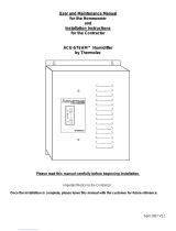
Steam Outlet
Flue outlet
(either side*)
Gas supply inlet
(either side*)
Water supply
(either side*)
Drain outlet
(either side*)
S/S 316 Evaporation
chamber
S/S 316 Combustion
chamber & heat exchanger
Front door
Water level sight glass
LCD display & control panel
General overview - Fig.1
Model No of
Modules
Steam
capacity
(kg/hr)
Natural Gas Propane Gas Current
at 230V
(Amp)
Multi-Steam
header
diameter
(mm)
Input
(kW) Consumption
(m3/h) Input
(kW) Consumption
(m3/h)
SKGE3-0501 N/P 1 50 43 3.9 45 1.7 3.5 76
SKGE3-0701 N/P 1 70 60 5.4 63 2.4 3.5 76
SKGE3-0801 N/P 1 80 68 6.1 71 2.7 3.5 76
SKGE3-1001 N/P 1 100 84 7.6 88 3.4 3.5 76
SKGE3-1202 N/P 2 120 103 9.3 108 4.2 4.5 76
SKGE3-1502 N/P 2 150 119 10.8 125 4.8 4.5 100
SKGE3-1702 N/P 2 170 144 13.0 150 5.8 4.5 100
SKGE3-2002 N/P 2 200 169 15.3 175 6.8 4.5 100
SKGE3-2503 N/P 3 250 212 19.2 220 8.5 6.0 100
SKGE3-2703 N/P 3 270 228 20.7 238 9.2 6.0 100
SKGE3-3003 N/P 3 300 253 22.9 263 10.2 6.0 100
SKGE3 3504 N/P 4 350 296 26.8 308 11.9 7.5 100
SKGE3-3704 N/P 4 370 313 28.3 326 12.6 7.5 100
SKGE3-4004 N/P 4 400 338 30.5 351 13.6 7.5 100
Notes: 1 - Maximum static duct pressure is 1.250 kPa. For higher static duct pressures please consult NEP or its authorized
distributor.
2 - Standard Humidifier is designed for Natural ventilation combustion air, ‘’Ducted Combustion Air’’ option is
available upon request, see stage 6 of installation.

SKGE3 Steam Humidifier
8
Dimensions & Weights
B
A
C
E
F
F
F
D
G
H
I
General dimensions - Fig. 2
General Dimensions & weight & Steam Outlets detail
Model Nb of
module
No of
Steam
Outlets
Steam
Outlet
Diam.
Dimensions in mm Weight
(Kg)
A B C D E F G H I Empty Full of
water
SKGE3-0501 N/P
SKGE3-0701 N/P
SKGE3-0801 N/P
SKGE3-1001 N/P 1 1
Ø76 1372 610 56] 230 460 145 200
SKGE3-1202 N/P
SKGE3-1502 N/P
SKGE3-1702 N/P
SKGE3-2002 N/P 2 2
Ø76 1372 1220 560 230 460 610 920 274 384
SKGE3-2503 N/P
SKGE3-2703 N/P
SKGE3-3003 N/P 3 3
Ø76 1372 1830 560 230 460 610 920 1680 431 600
SKGE3 3504 N/P
SKGE3-3704 N/P
SKGE3-4004 N/P 4 4
Ø76 1372 2440 560 230 460 610 920 1680 2290 576 800

SKGE3 Steam Humidifier
9
Dimensions & Weights
Position & Dimension of connections
370
560
51
152
436
378
102
1105
1257
1372
25
Electrical
control
Power
supply
Flue
Gas
supply
Front
door
Main
Drain
Pan
drain
127
Water supply
270
Connections position - Fig. 3
(all dimensions in mm)
Model Nb of
module
Dimensions in mm
Drain
Outlet
Diam.
Pan
Drain
Diam.
Water
Inlet
Diam.
Gas
Inlet
Diam.
Flue
Outlet
Diam.
SKGE3-0501 N/P
SKGE3-0701 N/P
SKGE3-0801 N/P
SKGE3-1001 N/P 1 Ø19 Ø15 ؽ”
BSTP Ø1”
BSTP Ø76
SKGE3-1202 N/P
SKGE3-1502 N/P
SKGE3-1702 N/P
SKGE3-2002 N/P 2 Ø38 Ø15 ؽ”
BSTP Ø1”
BSTP Ø100
SKGE3-2503 N/P
SKGE3-2703 N/P
SKGE3-3003 N/P 3 Ø38 Ø15 ؽ”
BSTP Ø1-½”
BSTP Ø125
SKGE3 3504 N/P
SKGE3-3704 N/P
SKGE3-4004 N/P 4 Ø38 Ø15 ؽ”
BSTP Ø1-½”
BSTP Ø125
Note: Drain outlet, water supply inlet, gas supply inlet and flue outlet are located on the right hand side of the humidifier. Left
hand side location of any of these outlets or inlets is available upon request.

SKGE3 Steam Humidifier
10
Dimensions & Weights
Option - Ducted combustion air inlet dimension
J
K
M
L
L
L
N
O
6'’(150)
Ducted combustion air dimensions - Fig. 4
(all dimensions in mm)
Model No of
modules
No of
Air
inlet
Dimensions in mm
Air
inlet
Diam. J K L M N O
SKGE3-0501 N/P
SKGE3-0701 N/P
SKGE3-0801 N/P
SKGE3-1001 N/P 1 1
Ø51 448 352 - - - -
SKGE3-1202 N/P
SKGE3-1502 N/P
SKGE3-1702 N/P
SKGE3-2002 N/P 2 2
Ø51 448 352 609 962 - -
SKGE3-2503 N/P
SKGE3-2703 N/P
SKGE3-3003 N/P 3 3
Ø51 448 352 609 962 1571 -
SKGE3 3504 N/P
SKGE3-3704 N/P
SKGE3-4004 N/P 4 4
Ø51 448 352 609 962 1571 2180

SKGE3 Steam Humidifier
11
Dimensions & Weights
Option - Weather proof enclosure general dimension and weight
T
U
V
W
Weather proof enclos. 1 to 3 modules configuration – Fig. 5
W
TV
U
Weather proof enclose. 4 modules configuration – fig. 6
128
302
136
1667
1462
174
DRAIN
WATER SUPPLY
GAZ SUPPLY
STEAM OUTLET
FLUE TERMINAL
POWER SUPPLY
ELECTRICAL
CONTROL
FRONT DOOR
COMBUSTION
AIR INLET
494
Weather proof enclosure
Connections position 1 to 3 modules configuration – Fig. 7
(All dimensions in mm)
136
1462
1667
751
926
1117
FLUE TERMINAL
(X2)
STEAM OUTLET
(X2)
ELECTRICAL
CONTROL
POWER
SUPPLY
COMBUSTION
AIR INLET
DRAIN
WATER SUPPLY
GAS SUPPLY
Weather proof enclosure
Connections positions 4 modules configuration – Fig. 8
(All dimensions in mm)
Model No of
modules
Dimensions (mm) Weight (kg)
T U V W
Empty Full of
water
SKGE3-0501 N/P
SKGE3-0701 N/P
SKGE3-0801 N/P
SKGE3-1001 N/P 1 1867 647 841 611 285 340
SKGE3-1202 N/P
SKGE3-1502 N/P
SKGE3-1702 N/P
SKGE3-2002 N/P 2 1867 1308 841 611 472 582
SKGE3-2503 N/P
SKGE3-2703 N/P
SKGE3-3003 N/P 3 1867 1963 841 611 653 818
SKGE3 3504 N/P
SKGE3-3704 N/P
SKGE3-4004 N/P 4 1867 1308 1616 1234 830 1050

SKGE3 Steam Humidifier
12
Handling & Unpacking
!
Lifting or handling MUST only be carried out by trained and qualified personnel. Ensure that
the lifting operation has been properly planned, risk assessed and that all equipment has
been checked by a skilled and competent Health & Safety representative and effective
control measures put in place.
It is the customer’s responsibility to ensure that operators are trained in handling heavy
goods and to enforce the relevant lifting regulations.
Any personnel handling or lifting the SKGE3 Steam Humidifier MUST follow the Lifting
Operations and Lifting Equipment Regulations 1998 and Approved Code of Practice L113.
The regulation imposes duties on employers and self employed persons and persons who
have control, to any extent of lifting equipment.
Refer to Dimensions & Weight section for system dry weights.
Handling and
Lifting
The SKGE3 Steam Humidifier MUST always be handled and lifted with care and should
remain within its original packaging for as long as possible prior to installation
The SKGE3 Steam Humidifier package may be carried using a fork lift from the underside.
Caution should be exercised to ensure balanced load before lifting.
Lifting of SKGE3 Steam Humidifier MUST always be carried out using the appropriate
Neptronic Lifting Bracket (sold separately), see fig. 9.
Lifting sling angle should be greater than 30˚ to the horizontal.
Optional weather proof enclosure is provided with four (4) lifting eyelets located at each
corner on the top of the enclosure, see fig. 10.
(Fig. 9) Standard enclosure
4 lifting eyelets
(Fig. 10) Option Weather proof enclosure
Unpacking SKGE3 Steam Humidifier is shipped in a wooden crate.
Ensure packing wooden crate and skid is removed prior to commissioning.
List of
accessories
supplied
Standard enclosure Weather proof enclosure
2 sets of keys.
2 adjustable steam hose collars per
module to connect to connect on the
steam output.
SKGE3-2503 to 4004:
1 Flue pipe connector Ø125mm
2 adjustable steam hose collars per
internal steam manifold.
3 spare clamps and Allen screws to
secure doors.
Startup check list & Combustion field adjustment instructions.
The present Installation Instructions.
Wiring diagram affixed onto the interior of the front access door.
Service and troubleshooting guide.
BACnet® communication module user guide (if BACnet® option is installed).

SKGE3 Steam Humidifier
13
Installation Overview
!
All installation work must comply with local regulations.
All work concerned with the installation of the SKGE3 Steam Humidifier MUST only
be performed by skilled and qualified technical personnel (e.g. qualified gas installer,
fitters, electricians, plumbers or technicians with appropriate training).
For the installation of the SKGE3 Steam Humidifier and associated components
there should be no special tooling requirements above that of a fitter’s toolkit.
Installation
method
statement
Stage1: Unit Positioning and Mounting
Stage 2: Steam Distribution Pipes Positioning & Installation
Stage 3: Gas Supply Connection
Stage 4: Water Supply Installation
Stage 5: Water Drain Connection
Stage 6: Combustion Air Installation
Stage 7: Flue Gas Venting Connection
Stage 8: Electrical Supply and Installation
Stage 9: Electrical Control Connections
Stage 2
Stage 4
Stage 5
air
Stage 6 Stage 7
Stage 8
Stage 3 Stage 9
or
air
To drain
air
air
air
air
Stage 1
Installation overview - Fig. 11

SKGE3 Steam Humidifier
14
Stage 1 – Unit Positioning and Mounting
Safety
considerations
!
Any installation work MUST be carried out by suitably qualified personnel.
The following considerations should be made before deciding upon the location for
the SKGE3 Steam Humidifier:
Locate the SKGE3 Steam Humidifier in an area clear of combustible
materials, gasoline, and other flammable vapours and liquids.
Do not install in potentially explosive or flammable atmospheres laden with
grain dust, sawdust, or similar airborne materials.
If the appliance is installed in an insulated area, it must be kept free and
clear of insulating material. Insulating materials may be combustible.
If insulation is added after the humidifier is installed, an inspection of the
humidifier area must be carried out to make sure that there is no insulation
coming into contact with the humidifier.
Provide adequate room ventilation air in accordance with local codes and
regulations.
With the exception of ducted combustion air installation, do not locate units
in tightly sealed rooms or small compartments without provision for adequate
air for combustion and room ventilation.
Combustion and ventilation air must be supplied through a one permanent
low-level and one permanent high-level opening communicating directly with
the outside air.
Humidifier flue gases must be vented to the outdoors.
Locate the humidifier as near as possible to an outside wall or roof so that
the flue pipe from the humidifier is short and direct.
Locate the SKGE3 Steam Humidifier on a water proof floor or install a drain
pan beneath the humidifier.
Positioning the
Humidifier
The humidifier must be installed to ensure the steam hose length is kept to
the shortest possible length.
For flexible steam hose: the total steam line length should not exceed 5
meters. For longer distances use insulated hard piping.
For insulated hard piping: the total steam line length should not exceed 15
m. For longer steam line runs, consult factory.
The humidifier should be located in an area that is fully accessible for
inspection and servicing. Observe the minimum access distances as detailed
in stage 1 of installation instructions.
Ambient
condition &
Altitude
The humidifier location should have an ambient temperature of less then 30˚C.
Combustion burner of SKGE3 Steam Humidifier is self adjusting for any altitude;
Burner will maintain proper combustion and low emission at any altitude.
Steam capacity will be affected by altitude over 1050 m elevation above sea level.
Please refer to the table below to anticipate the ratio of output reduction:
Altitude above sea level (m) Output reduction (%)
0 to 1050 0
1051 to 1350 2
1351 to 1650 4
1651 to 1950 6
1951 to 2250 8

SKGE3 Steam Humidifier
15
Stage 1 – Unit Positioning and Mounting
500mm
minimum
800mm
minimum
600mm
minimum
Standard enclosure clearances - Fig. 12
0.6m
minimum
0.5m
minimum
0.8m
minimum
Weather proof enclosure clearances - Fig. 13
Minimum
Clearances Minimum clearances are :
Standard enclosure Weather proof enclosure
Top, 0.50m minimum
Both sides, 0.60m minimum
Front, 0.50m minimum
Top, 0.50m minimum
Connection side, 0.60m minimum
Front, 0.8meter minimum
Note: Above minimum clearances are indicated for inspection and servicing access.
SKGE3 Steam Humidifier is designed for a 0 clearance to combustible material,
except for Top and Front, where minimum clearance to combustible material is
respectively 500 and 762 mm
The humidifier is designed to be installed directly on the floor.
Provide a level, solid foundation for the humidifier.
Ensure that the floor beneath the humidifier is water proof to withstand any water
spillage during servicing or if a problem occurs.
The humidifier is provided with adjustable legs in order to ensure proper level.
Roof curb for
weather proof
enclosure 4 holes (Ø 12)
to bolt
humidifier to
roof curb.
16
102
610
305
1/2xU
U
U - 204
Weather proof enclosure base dimensions(in mm) - Fig. 14
Ensure that roof curb is structurally built to support the weight of the SKGE3
humidifier.
Roof curb should provide proper level to the humidifier.
Base of the weather proof enclosure is provided with 4 holes Ø12mm to bolt SKGE3
humidifier to roof curb.

SKGE3 Steam Humidifier
16
Stage 2 – Steam Distribution Installation
Fundamental
Design Concepts
!
1. Maximum steam velocity in a pipe should not exceed 12m/s. Velocities above
this will generate noise.
2. Minimum steam pipe gradient should be 7˚ i.e. 125mm rise in 1000mm run.
3. Normally, the lowest point of any steam hose or rigid pipe (steam conduit) must
be the humidifier. Otherwise, a steam trap (S trap) should be installed at the
lowest point of the steam conduit. This steam trap should be installed higher
than the static pressure of the system by at least 50mm.
4. Total length of the flexible steam hose should not exceed 5 m or insulated rigid
piping should not exceed 15 m.
5. Whenever possible use rigid copper piping, flexible steam hose can be used for
short runs or for interconnecting between rigid pipe runs, ensure that there is no
kink in the flexible hose.
When using rigid copper pipe, insulation should be used to diminish
condensation build up.
Min. 7°
Correct Installation
Single module
humidifier with
Multisteam.
Static pressure
+ 50mm
Steam distribution correct installation 1 - Fig. 15a
Min. 7°
Correct Installation
Single module humidifier with 2 SAMB E2 manifolds
Static pressure
+ 50mm
Steam distribution correct installation 2 - Fig. 15b
Incorrect Installation
Incorrect installation - Fig. 16
6. Connection pipe sizes between SKGE3 and steam distributor in the duct should
be :
76mm up to 120kg/h
108mm up to 240kg/h
133mm up to 255kg/h
7. All Humidifier below 100kg/h capacity should use standard Neptronic®
SAMB E2 Steam distribution pipes, Multi-Steam can be offered if shorter
absorption distances are required.
8. All Humidifiers above 100kg/h capacity should use Multi-Steam configuration.
9. All Humidifiers above 240kg/h should use 2 Multi-Steam units per Air Handling
Unit (AHU) or air Duct with an equal duty split to each Multi-Steam

SKGE3 Steam Humidifier
17
Stage 2 – Steam Distribution Installation
Steam outlet
configuration for
weather proof
enclosure
Integrated steam manifold
Steam outlet
Weather proof enclosure single steam outlet - Fig. 17
SKGE3 humidifier with weather proof enclosure is provided with an integrated steam
manifold with outlet on one or other side of the humidifier.
By default steam outlet will be on the right side of the humidifier (when facing the
control panel). Steam outlet side can be switch to left upon request to factory.
Weather proof
enclosure steam
outlet dimension
& quantity
Model Steam outlet
Qty Steam outlet
diameter
SKGE3-
0501, 0701, 0801, 1001 1 Ø76mm
SKGE3
1202, 1502, 1702, 2002 1 Ø108mm
SKGE3
2503, 2703, 3003 1 Ø133mm
SKGE3-
3504, 3704, 4004 2 Ø108mm

SKGE3 Steam Humidifier
18
Stage 2 – Steam Distribution Installation
Selection of
steam
distribution
manifolds
1. The minimum steam manifold length that can be used with the SKGE3-0501 to
SKGE3-1001 is 900mm. Any manifold below this dimension will have insufficient
outlet spigots to allow proper steam distribution.
2. If duct size is below 900mm width it will be necessary to either fit multiple pipes
or Multi-Steam.
Horizontal duct
H
2/5 H
120 mm
120 mm
Ø 78 mm
1/5 H
200 mm
air flow
Air duct
Horizontal duct – 2 manifolds - Fig. 18
H1/3 H
120 mm
120 mm
Ø 78 mm
1/6 H
250 mm
air flow
Air duct
250 mm
1/2 H
Horizontal duct – 3 manifolds - Fig. 19
Vertical duct W
min. 600 mm
1/2 H 1/4 H1/4 H
Min. 100 mm
Air duct
Vertical duct – 2 manifolds - Fig. 20
W
min. 900 mm
1/3 H 1/3 H
1/6 H 1/6 H
Min. 100 mm
Air duct
Vertical duct – 3 manifolds - Fig. 21

SKGE3 Steam Humidifier
19
Stage 2 – Steam Distribution Installation
Manifolds configurations
All Humidifiers above 100kg/h capacity should use Multi-Steam configuration
Single module
humidifier:
SKGE3-0501
Steam distribution manifolds
(SAMB E2)
minimum lenght = 900mm
Ø76mm
Ø15mm
Min. 7° pipe slope
Min. 100mm
Insulated pipe
H
Air Duct
Static pressure
+ 50mm
Min. 2/5 H Min. 100mm
Total length of steam conduit should not exceed 5 meters.
Steam pipe work SKGE3-0501 - Fig. 22
Single Ø76mm feed pipe should be connected to two (2) SAMB E2 Steam manifolds
with a suitable reduction at the lowest point to allow a Ø15mm condensate drain from
the main steam supply.
Single module
humidifiers:
SKGE3-0701
SKGE3-0801
SKGE3-1001
Min. 7° pipe slope
Ø76mm
Ø15mm Steam distribution manifolds
(SAMB E2)
minimum lenght = 900mm
Min. 100mm
Insulated pipe
H
Air Duct
Static pressure
+ 50mm
Min. 1/3 H
Total length of steam conduit should not exceed 5 meters.
Min. 100mm
Steam pipe work SKGE3-0701 to 1001 - Fig. 23
Single Ø76mm feed pipe should be connected to 3 SAMB E2 Steam manifolds with a
suitable reduction at the lowest point to allow a Ø15mm condensate drain from the
main steam supply.
/