Page is loading ...

Page 1 of 3 Revision 01 10/03/19
VLM5 Towing Kit Installation & User Guide
1 Introduction
The VLM5 is an electronic module that is used in many motorhomes to control the rear LED road lighting. The unit
includes monitoring of the motorhome rear direction indicators so that if / when a failure occurs this is shown on the
vehicle dashboard (and by a flashing indicator on the VLM5 unit).
The VLM5 also includes the facility to connect an optional towing harness to provide a 13-pin socket for connection
to a light board, trailer or caravan. When this socket is being used the direction indicator monitoring is extended to
cover the device / vehicle being towed.
To provide this extended indicator monitoring you need to follow the connection process described further below.
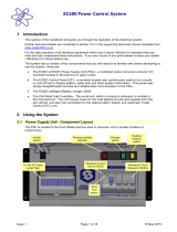
2 Overview
Trailer
Lights
OUT
Vehicle
Lights
OUT
Lighting
Signals
IN
Power IN
Negative IN
The VLM5 is usually installed in the rear of the motorhome in a dry and damp free area. If you do need to disconnect
or remove the unit, please ensure the Negative IN connection is removed last when disconnecting, and connected
first when reconnecting.
3 User Operation
The VLM5 unit operates automatically and does not need any special or additional actions. The unit is supplied with
power from the Sargent EC series Power Supply Unit (PSU) and therefore this unit should always be turned on when
using your vehicle.
If your vehicle has been fitted with the optional towing wiring harness please follow the steps below to connect your
light board, trailer or caravan.
1) With the Sargent PSU ON and the vehicle ignition OFF, plug the light board, trailer or caravan into the 13-pin
socket.
2) The vehicle will now detect the trailer and flash each indicator to ‘learn’ the extra indicators fitted on the light
board, trailer or caravan.
3) You can now start the engine when required and use the vehicle / trailer combination.
4) When you have finished towing, turn the engine / ignition off and unplug your light board, trailer or caravan.
If you have problems with lamp failure indication on the vehicle dashboard, please see the fault-finding section
further below.

Page 2 of 3 Revision 01 10/03/19
VLM5 Towing Kit Installation & User Guide
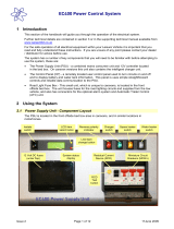
4 Towing Harness Installation
The towing wiring harness is designed to plug into the VLM5, connect to an earth stud under the vehicle and then run
rearwards to the 13-pin socket.
The following describes the basic steps to install the towing harness. It does not cover normal workshop practices for
routing the harness, fixing the 13-pin socket, sealing through the floor and / or other mounting / fitting operations.
If you are unsure how to install the towing harness please ask your dealer or installation professional for help /
advice.
3) Referring to the overview photo, unplug the Power Input plug
from the VLM5 and plug it into connector C on the towing
harness.
4) Plug connector B of the towing harness into the VLM5 power
input connector.
5) Plug connector A of the towing harness into the Trailer Lights
output connector on the VLM5.
6) Connect ring terminal D to the earth bonding bolt in the chassis
below the vehicle.
7) Complete the installation by clipping / fixing the harness and
the 13-pin socket. Seal any apertures as required.
1) Firstly, locate the VLM5 and the earthing
stud below the vehicle and route the
towing harness from the VLM5 via the
earth stud to the 13-pin socket location.
2) The 13-pin socket E is usually prewired,
but if not please connect the individual
cables as per the diagram below.
View looking into the socket from the front
(mating surface under flap)
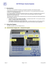
5 Testing
After installation of the harness the unit should be tested for correct operation as follows:
1) Ensure the Sargent PSU is turned ON.
2) View the VLM5 and look for a red LED illuminated (this LED in located on the circuit board near the power input
connector).
If you do not see an LED illuminated, please turn the side-lights on and recheck.
Vehicle
3) With a helper viewing the rear of the vehicle, turn each light on / off confirming their correct operation.
4) If you wish to force a failure to test the dashboard indication, turn on the left or right indicator, and with it flashing
disconnect / unplug the light cluster / indicator connection. This should then cause the dashboard warning to
show a ‘failure’ and the red LED on the VLM5 to start flashing. Reconnect the indicator to clear the fault.
Light board, trailer or caravan
5) With the vehicle ignition OFF, plug the light board, trailer or caravan into the 13-pin socket.
6) The vehicle will now detect the trailer and flash each indicator to ‘learn’ the extra indicators fitted on the light
board, trailer or caravan.

Page 3 of 3 Revision 01 10/03/19
VLM5 Towing Kit Installation & User Guide
7) Now start the engine, wait 10 seconds and then unplug the 13-pin connector to simulate an indicator failure on
the light board, trailer or caravan. This should then cause the dashboard warning to show a ‘failure’ and the red
LED on the VLM5 to start flashing. Reconnect the 13-pin socket to clear the fault.
8) Turn off the engine / ignition, testing is now complete.
6 Fault Finding
Problem / issue
Suggested fix
When connecting a light board, trailer
or caravan you are not seeing the
indicators flash to confirm learning of
the extra indicators.
Ensure the Sargent PSU is turned on.
Check the VLM5 red LED is illuminated.
Ensure the ignition is turned off, as learning can only take place with the
engine stopped.
If the light board, trailer or caravan uses LED brake lights these may not
provide enough load to trigger the trailer detection / indicator learn
process. In this case you will need to add an extra ‘load’ to the brake
light circuit of the light board, trailer or caravan by adding a load resistor
(we recommend a 50W 6 Ohm resistor or similar. Please note this
resistor may become hot during use so should be mounted in a suitable
place).
With no light board, trailer or caravan
connected, you occasionally see a
random flash of the rear indicators.
This can be caused by a false trigger of the trailer detection / learning
process.
On some vehicles a change was made to the high-level brake light
which in some cases can cause this problem.
A software update is available for the VLM5 to correct this issue. Make
a note of the software number on the unit and then contact Sargent
support for more information and advice on how to update the unit.
When using the vehicle (without a light
board, trailer or caravan connected)
you are seeing lamp failure indication
on the dashboard.
Ensure the Sargent PSU is turned on.
Turn the ignition off, wait 10 seconds and then turn it back on.
Check the VLM5 red LED is illuminated and not flashing.
If the LED is flashing check the connections at the VLM5 and the rear
indicators.
Make a note of the software number on the units and then contact
Sargent support for further help.
7 Help & Assistance
If you do experience any problems with the installation of the towing harness or operation of the VLM5 please contact
the Sargent Support team on 01482 678981 or email them at support@sargentltd.co.uk
/