SCI
I
SC2
I
SC4
I
SC8
SOUNDSTREAM
CAPACITOR
SC1/SC2/SC4/SC8
MANUAL

Dear
Customer
Congratulations on your purchase of the world's finest brand of car audio
amplifiers.
At SOUNDSTREAM we are committed to producing musical
reproduction at its best, and we are pleased
you chose our product. Through
years of critical testing procedures and hand craftsmanship, we have created a
wide range of products that reproduce music with all the clarity and richness
you deserve.
For maximum performance we recommend you have your new
SOUNDSTREAM product installed by an Authorized SOUNDSTREAM
Dealer. Please read your warranty and retain your receipt and original
carton for possible future use.
!!
Attention
!!
Continuous, excessive exposure to sound pressure levels in excess of 85 dB
can cause a loss in hearing. While SOUNDSTREAM sound systems are
capable of producing sound pressure levels greater than
85dB,they are also
designed for enjoyment at reasonable levels. Please observe all local sound
ordinances while listening to your SOUNDSTREAM sound system
TABLE
OF
CONTENTS
SPECIFICATIONS..
...................................................................
1
.............................................
INSTALLATION AND MOUNTING..
.I
............................................
BENEFITS OF USING A CAPACITOR..
.2
.........................................................................
THE FEATURES
.3
CHAKGING A CAPACITOR
............................................................
.4
DISCHARGING CAPACITOR..
....................................................
.5
......................................................................................
WIRING
.6
WARRANTY.
............................................................................
.8

SPECIFICATIONS
Model:
SCl
Capacitance
-----------
1 farad
(
1,000,000 micro farad)
Working Surge Voltage
.........................
24 V DC
E.S.R.(Equivalent Series Resistance)---------0. 0014 OHM
Capacitance Tolerance--------------------------* 10%
I
Model:
SC2
Capacitance
-----------
2
farad
(
2,000,000 micro farad)
Working Surge Voltage
.........................
24 V DC
E.S.R.(Equivalent Series Resistance)---------0. 0014 OHM
Capacitance Tolerance
..........................
*
]070
Model:
SC4
Capacitance
-----------
4.0 farad
(
4,000,000 micro farad)
Working Surge Voltage
.........................
24 V DC
E.S.R.(Equivalent Series Resistance)---------0. 0013 OHM
Capacitance Tolerance--------------------------+
10%
Model:
SC8
Capacitance
-----------
8.0 farad
(
8,000,000 micro farad)
Working Surge Voltage
.........................
24 V DC
E.S.R.(Equivalent Series Resistance)---------0. 0014 OHM
Capacitance Tolerance
..........................
*
10%
INSTALLATION AND MOUNTING
For maximum performance your SOUNDSTREAM Stiffening Capacitor
should be mounted as close to your
amplifier(s)as possible. A low resistance
connection between the amp and the capacitor is required for maximum
performance. High resistance connections or long wire lengths reduce the
capacitors effectiveness. Be sure to firmly tnount the capacitor to a
stationary object in the vehicle. Use caution when selecting a suitable
location. Be aware of any hazards that may cause a short circuit, which will
damage the capacitor.
Note: You must first attach the mounting tabs to the Stiffening Capacitor
before mounting it. Use the supplied hardware shown in the picture to the
right. Notice the stnall mounting screw hole in the capacitor chassis.
BENEFITS OF USING

The
Features:
a)
Multi
4
digital
8
character hi-end Orange display DC voltage meter that
can measure 0.0
1
DCV range.
b)
Discharging status Orange flash LED line on metal case beside
c)
Reverse pole connecting PCB buzz warning function. If the capacitor is
connected incorrectly by reversing the positive and negative wires during
the installation process the PCB will issue a
45
second noise to warn you.
d)
Over voltage limit and low battery voltage limit warning. When the
system voltage peeks over
17.5
DCV or LESS than 10 DCV. The buzzer
on the PCB will issue an audible noise warning.
e)
lowest inner E.S.R. and largest moment discharge power.
f)
Positive1 Negative 014 gauge pole connecting power ring terminal.
g) Hi-end chrome plated metal case
014AWGPOWERWlRE
OUTPUT
(-1
NEGATIVE
CHARGING THE CAPACTITOR
The capacitor must be charged before connecting the Power and
Ground cables directly. Failure to charge the capacitor will result in
a large spark generated from the rapid inflow of current.
To Charge the capacitor:
1.
Make your positive terminal connections and tighten the bolt.
Caution: Do not over-tighten the bolts! Stripped terminals are
not covered under the capacitors warranty.
2.
Before connecting the ground cable, place the supplied
CHARGING

Once the capacitor is charged, the Orange LED will light and the
VOLTAGE METER will turn on. The voltmeter will continuously
display system voltage while system is in use. The voltmeter will
turn
off automatically when the sound system is not in use.
BEFORE MAKING ANY POWER CONNECTIONS,
DISCONNECT BATTERY POWER FROM YOUR SOUND
SYSTEM!
DISCHARGING THE CAPACITOR
To Discharge the capacitor: With battery power disconnected. Place light
bulb or resistor across the capacitors positive and negative terminals until
light goes out or for three minutes if using a resistor.
DISCHARGING
BULB
\
DISCHARGING
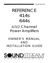
WIRING
1. Disconnect the positive cable connected to your car battery.
2.
The capacitor will be installed between the amplifiers
and the battery supplying power.
3.
Do not connect the ground to the capacitor until the
capacitor is charged.
4.
Connect the power wire of the amplifier to an input on the
positive distribution
terminal block on the Capacitor.
5.
Connect the power wire from the battery to the capacitor.
6.
Again, do not connect the ground to the capacitor
until the capacitor is charged using the light bulb.
7.
Reconnect the positive power cable to the battery.
8.
Charge the capacitor using the capacitors ground as
shown in the figure above.
9.
Connect the ground cable from one of the negative
input terminals to a solid clean chassis ground.
10.
Below is an illustration showing correct wiring for the
capacitor.

**
LIMITED
WARRANTY
LENOTH
OF
WARRANTY
ONE YEAR
Warranty applies only to The products sold to consumers by Authorized
SOUNDSTREAM Dealers in the United States of America or its possessions. Products
purchased by consumers from Authorized SOUNDSTREAM Dealer outside of the
USA
are
covered only by that country's distributor.
WHO
IS
COVERED
This warranty covers only the
original purchaser
of SOUNDSTREAM product
purchased from an Authorized SOUNDSTREAM Dealer in the United States.
For a list of Authorized Internet Retail Stores go to SOUNDSTREAM web. In
order to receive service, the purchaser must provide SOUNDSTREAM with a copy
of the receipt stating the customer name, SOUNDSTREAM Authorized dealer
name, product purchased and date of purchase. Products found to be defective
during the warranty period will be repaired or replaced (with a product deemed to
be equivalent) at
SOUNDSTREAM's discretion.
WHAT Is NOT COVERED
1.
Damage caused by accident, abuse, improper operations, water, or theft.
2.
Any cost or expense related to the removal or reinstallation of product.
3.
Repair Service performed by anyone other than SOUNDSTREAM's Repair
Department.
4.
Any product which has had the serial number defaced, altered, or removed.
5.
Any product purchased outside the United States.
6.
Any product not purchased from
an
Authorized SOUNDSTREAM Dealer.
LIMIT
ON
IMPLIED WARRANTIES
Any implied warranties including warranties of fitness for use and merchantability are
limited in duration to the period of the express warranty set forth above. Some states
do not allow limitations on the length of an implied warranty, so this limitation may not
apply. No person is authorized to assume for SOUNDSTREAM any other liability in
connection with the sale of the product.
/