Page is loading ...

DTA
Automorwe
Digital to
Analog
Processor
OWNER’S MANUAL
SOUNDSTREmAl’v’~
TECHNOLOGlES

DTA 1
Digital
to
analog
Processor
OWNER’S MANUAL
DESIGN
,
FEATURES
I
Thank you for purchasing the Soundstream
DTAl
.
You now own
the finest automotive Digital to Analog processor made, a precision
component with audiophile performance.
For maximum performance, we suggest you take a few moments
to read through this manual, to better acquaint yourself with the
design features and capabilities of your new
DTAl
.
This Soundstream product is the result of the combined efforts of
Krell Digital and Soundstream Technologies. It is made with
American craftsmanship and the highest quality control standards, to
provide you with many years of listening pleasure. To further help
protect your investment and to aid us with service questions, please
fill in and retain the following requested information:
Model Number:
Serial Number:
Dealer’s Name:
Date of Purchase:
Date of Installation:
We’ve designed the DTAl (as shown in Figure 1) to be an audio-
phile replacement for the standard digital to analog (D/A) proces-
sors found in many of today’s mass-marketed, CD and DAT mobile
components. When you bypass your source’s D/A circuits and route
the digital output to the
DTAl,
your mobile audio system will be
greatly enhanced by these features:
l
18-bit
Digital Processor with 8x Oversampling Digital Filter
-
this high-performance processor resamples the incoming digital
signal to create an 8x oversampled, 1
a-bit
datastream. With 8x
oversampling, more data points are added to create a more accu-
rate waveform. This allows the use of a simpler, better-sounding
analog filter at the converters’ outputs, for precise analog signal
reconstruction.
l Hybrid Digital to Analog Conversion
(DAC)
System
-
our unique
combination of traditional, oversampled “ladder” and newer
“1 -bit” DAC technologies. Resampled data is split up and han-
dled by two separate converters per channel, working in parallel.
The result is an accurate analog conversion with the lowest possi-
ble noise and distortion specifications.
2
Figure
I
l tine level Analog Output Stages
-
to amplify the analog signals
coming from the
DACs.
This Krell preamplifier has all-discrete,
Class A outputs that feature low-output impedance to drive long
cable runs. The design also includes a modified version of Krell’s
proprietary home audio grounding system, with separate analog
power supply to insure minimal digital signal crosstalk. With it
you’ll hear cleaner, more transparent music reproduction without
annoying low-level digital artifacts.
l Three Inputs with Priority Switching
-
for connection to digital
input signals. One input uses an Optical connector for interface to
industry-standard fiber-optic cable in lieu of coaxial cable. The
other two inpuk connect to standard 75 ohm coaxial cables ter-
minated with RCA connectors. The
DTAl
is compatible with CD,
DAT, and the new DCC digital cassette formats at both 44.1 and
48 kHz sampling frequencies. Through clever sensing circuits, the
DTAl
will automatically choose the Optical input as the source
whenever a signal is present at that connection (as explained in
the Installation section). Similarly, for the 75 ohm inputs, input 1
has priority over input 2. Switching between sampling frequen-
cies is transparent.
l Quality Construction -we use only premium parts to build each
DTAl,
including double-sided masked glass epoxy circuit boards,
polypropylene capacitors, gold-plated RCA input/output connec-
tors, and a rugged heavy gauge steel enclosure.
l
Simple
lnstdation
-
the
DTAl
can be mounted in any convenient
location inside the vehicle with four sheet metal screws. The DTAl
obtains power from the standard
12
Vdc automotive electrical
system and uses the audio system’s remote turn-on voltage for cir-
cuit activation. Once installed, the
DTAl
operates automatically
without any need for adjustments or controls.
3

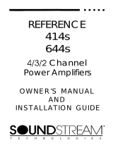
CONNECTIONS
Figure 2
INSTALIATION
l-
-l
Wiring Layout
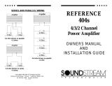
In general, you should plan to connect the
DTAl
between the digital
source and the control head unit, as shown in Figure 3. If you are
using an equalizer or active crossover, be sure to insert the
DTAl
in
the chain before any of these components.
Determine how your vehicle’s wiring is laid out, and plan to run
your new wiring along the same routes.
Be
sure to keep power wires
away from
all
audio signal wires. (NOTE: Wires containing audio
signals can cross a power wire, but not run alongside it.)
You can route the new wires under the carpeting, but make sure
they do not interfere with the vehicle’s normal operation. Keep all
Power
Connections (Barrier Strip)
Remote: Connect to control
head
unit remote turn-on.
Ground: Connect to Chassis Ground.
+12V
Connect to
+12
Vdc. An adjacent LED indicator confirms
power to
DTAl
.
Digital Inputs
Optical: Fiber-optic
lack
-
First Digital Input.
1: 75Q RCA coaxial
lack
-
Second Digital Input.
2:
75~
RCA coaxial
lack
-
Third Digital Input.
Analog Audio Outputs
Left: RCA audio
lack
-
Analog Left Output.
Right: RCA audio jack
-
Analog Right Output.
Automotive sound system installations can be tricky, especially for
first-timers. For this reason, we recommend using o professional
installer, who has the tools and, more importantly, the experience
to do the
lob
right. If you decide to install the equipment yourself,
we hope this manual will serve as a helpful guide.
Recommended Signal Cables
The DTAl uses custom gold-plated RCA
iacks
for analog and 2
of the available 3 digital audio connections. For best analog signal
transfer, we recommend using
Soundstream
DL.1
Stereo Audio
Cable, Streamline Audio Cable, or an equivalent premium cable.
For digital audio connections, use a precision flexible 75 ohm
cable like Soundstream’s
HRV.
1, 75 ohm Interconnect Cable, to
insure accurate transmission of digital signals.
DTAl
Figure 3
7-Way
Electronic Crossover
Zenter
Channel
Speakers
Aftermarket Source Unit
(CD, DA J or Cassene Player)
Subwoofers
4

wires inside the vehicle, hidden from passengers. An exposed wire
can inadvertently be pulled out, and may cause disconnection or
shorting.
location and Mounting
The
DTAl
is compact in size and it generates virtually no heat. It
can be located almost anywhere within the passenger compartment,
trunk, or storage area. However, do not install the
DTAl
in the
engine compartment or in any outside location exposed to dirt and
moisture.
Use the
DTAl
as a template to mark drill holes. Before mounting
the
DTAl
to your vehicle’s chassis, inspect the site for any hidden
brake or gas lines, wires, or cables.
After selecting a suitable location, mount the
DTAl
,
and then per-
form the following connection steps:
Connecting Audio Signal Cables
1.
Make sure power to your audio system is off.
2. Locate the Digital Output connector on the back of your CD or
DAT control head unit.
3. Connect an appropriate length of RCA coaxial cable from the
source’s digital output to digital 75
R
input 1 on the
DTAl
NOTE: If you use an optical link, connect an appropriate length of
fiber-optic cable from the source’s
digital
output
to
the Optical input
on the
DTAl
.
However, if you are installing a second source, remem-
ber that the
DTAl
uses automatic priority switching to select signals
at Optical input over those present at the 75 ohm inputs, 1 or 2.
Also, input 1 has priority over input 2. However, CD players not
equipped with o Remote On/Off control will continue generating
digital sync code which will be sensed by the DTAl. If this type
of player is part of your installation, we suggest connecting
the
unit to a lower priority input via RCA cables.
4. Repeat steps 2 and 3 to connect an additional CD or DAT control
head unit.
5. Connect an appropriate length of high-performance stereo RCA
audio cable from the Left and Right analog audio outputs on the
DTAl to the CD or Aux input of your head unit or preamp in your
mobile system chain (see Figure 3).
Connecting Power Wires
6. With power still off, connect a black wire
(18
gauge) from the
Ground terminal to a good chassis ground (e.g., bare metal or bolt,
not painted or coated).
7. Connect another (e.g., orange or aqua) wire from the Remote
terminal to your control head unit’s remote turn-on connection.
NOTE: This connection enables the DTAl to follow a timed sequence
for minimal turn-on and turn-off thumps and is required for circuit
activation.
8. Connect a red wire
(18
gauge) from the
+12V
terminal through a
0.75 A in-line (fast-blow) fuse, to a constant
+12
Vdc source, so
that it is “hot” even when the ignition is off. Try connecting it to the
battery cable itself, or tapping into a power lead on the control
head unit (see Figure 3).
DTA 1 Operation
9. Turn on your control head unit, selecting a source connected to the
DTAl,
and slowly increase the volume while listening to a familiar
musical selection. With proper instollation, your
DTAl
should pro-
vide you with an increased sense of transparency and music repro-
duction. There are no adjustments or controls.
NOTE: If you experience problems at this point, review the installa-
tion steps and check all your connections. If you are installing the
DTAl as part of a new system, try leaving the
DTAl
out of the chain
until you get your entire system operating properly first. Then repeat
steps 1 through 8 to insert the
DTAl
once again into the audio
system chain.
SERVICE
Your
DTAl
is protected by a limited warranty. Please read the
enclosed warranty information carefully. Should any problem occur,
contact your local Soundstream dealer.
SPECIFICATIONS
D/A
Converter
8x Oversompling,
18-bit/l-bit
hybird
Sampling Frequency
32 kHz, 44.1 kHz, 48
kHz
Frequency Response
5 Hz to 20
kHz,
f
0.25
dB
S/N
~100
dB,
A-weighted
Dynamic Range
96
dB
THD
<
0.03%,
20 Hz to 20 kHz
Channel Separation
-85dBQ
1
kHz
Minimum Recommended Load
6OOR
output
Level
2Vrms
Dimensions
8.1”(L)x5”(w)x
1.5”(H)
6
/