Page is loading ...

ATyS UL 1008
Transfer Switching Equipment
100, 200, 260, 400A
EN
INSTRUCTION
MANUAL
www.socomec.com
http://www.socomec.com/en/atys-ul-1008
To download, brochures, catalogues and technical manuals.

2
EN
INDEX
1. GENERAL SAFETY INSTRUCTIONS .......................................................4
2. INTRODUCTION .............................................................................5
3. QUICK START ...............................................................................6
...............................6
.....................................................................10
................................................................10
...............................................................11
........................................................................12
4.3.1. IP RATING IEC 60529 .................................................................12
4.3.2. OPERATING CONDITIONS ............................................................12
.................................................................12
..................................................................12
......................................................................12
4.3.3. STORAGE CONDITIONS .............................................................12
..................................................................12
......................................................12
.............................................................12
4.3.4. VOLUME AND SHIPPING WEIGHTS BY REFERENCE ATYS ...............................13
4.3.5. UL MARKING ........................................................................13
4.3.6. CE MARKING ........................................................................13
4.3.7. 2011/65/EU ROHS ...................................................................13
.............................................................................14
..................................14
.................................................................15
..............................................................15
......................................15
5.4.1. BRIDGING BARS (OPTIONAL ACCESSORY) ............................................15
5.4.2. MOUNTING OF TERMINAL COVERS (OPTIONAL ACCESSORY) ...........................16
..................................................16
..................................................16
5.4.3. MOUNTING OF ADDITIONAL AUXILIARY CONTACTS (OPTIONAL ACCESSORIES) ..........17
5.4.4. POWER TERMINAL CONNECTIONS (OPTIONAL ACCESSORIES) .........................17
......................................................................18
5.5.1. TYPICAL ATYS WIRING ...............................................................18
5.5.2. ATYS INPUT AND OUTPUT CONTACTS ................................................19
.......................19

3
EN
................................................................20
.....................................................................21
............................................................................21
.................................................................22
6.3.1. POWER SUPPLY .....................................................................22
6.3.2. FIXED INPUTS ......................................................................22
...................................................................22
...................................................23
................................................................23
6.3.3. FIXED OUTPUTS - DRY CONTACTS ....................................................24
...................................................................24
.....................................................24
..................................24
.................................................25
7. CHARACTERISTICS .......................................................................26
.............................................................27
.............................................................27
........................................................................28
........................................................28
..............................................30

EN
1. GENERAL SAFETY INSTRUCTIONS
This manual provides instructions on safety, connections and operation of the ATYS transfer switch
Whether the ATYS is sold as a loose product, as a spare, as an enclosed solution or as any other
personnel, in line with the manufacturers recommendations, following good engineering practices and after
having read and understood the details in the latest release of the relative product instruction manual.
This instruction manual must be made accessible so as to be easily available to anyone who may need to
read it in relation with the ATYS.
The ATY
Do not handle any control or power cables connected to the ATYS when voltage may be present
on the product directly through the mains or indirectly through external circuits.
DANGER WARNING CAUTION
RISK
Electric shock, burns, death
Possible personal injury
Equipment damage
As a minimum the ATYS complies with the following international standards:

EN
2. INTRODUCTION
ATYS transfer switches are designed for use in total system optional standby power applications for the safe
transfer of a load supply between a normal and an alternate source. The changeover is done in open transition and
11 and other international TSE standards as listed.
The ATY
ATYS transfer switching equipment ensures:
A complete product delivered as a fully assembled and tested solution.
An inherent failsafe mechanical interlock.
(Manual operation is functional with and without the motorization in place).
Straight forward installation with effective ergonomics.
Genset Genset
ATyS
ATyS
ATyS

6
EN
ATyS
Transfer Switch
UL 1008: Optional Standby Power
542 563 C - 12/14 - EN
QUICK START
100A, 200A, 260A, 400A
Printing informations: 1 color Black. White paper 90g/m
2
.
Printing size: 420x297. Final size 210x297. This page visible first.
Non contractual document.
Sub
j
ect to chan
g
e without notice.
www.socomec.com
To download, brochures, catalogues and technical manuals:
http://www.socomec.com/en/
atys-ul-1008
Preliminary operations
Check the following upon delivery and after removal of the
packaging:
■ Packaging and contents are in good condition.
■ The product reference corresponds to the order.
■ Contents should include:
Qty 1 x ATyS
Qty 1 x Emergency handle and fixing clip
Quick Start instruction sheet
Warning
Risk of electrocution, burns or injury to persons and /
or damage to equipment.
This Quick Start is intended for personnel trained in the
installation and commissioning of this product. For further
details refer to the product instruction manual available on
the SOCOMEC website.
■ This product must always be installed and commissioned
by qualified and approved personnel.
■ Maintenance and servicing operations should be
performed by trained and authorised personnel.
■ Do not handle any control or power cables connected to
the product when voltage may be, or may become present
on the product, directly through the mains or indirectly
through external circuits.
■ Always use an appropriate voltage detection device to
confirm the absence of voltage.
■ Ensure that no metal objects are allowed to fall in the
cabinet (risk of electrical arcing).
Failure to observe good enginering practises as well as to
follow these safety instructions may expose the user and
others to serious injury or death.
Risk of damaging the device
■ In case the product is dropped or damaged in any way it
is recommended to replace the complete product.
Accessories
■ Bridging bars and connection kits.
■ Terminal screens.
■ Auxiliary contacts (Additional).
■ Terminal lugs.
Spares
■ Motorisation module
For further details for spares and accessories, please refer
to the instruction manual in chapter -
"Spare parts and accessories"
STEP 1
Cabinet / Back Plate
Installation
STEP 3
COMMAND /
CONTROL terminal
connections
STEP 2
Connecting the
POWER section
STEP 4
Power SUPPLY
terminal connections
STEP 5
CHECK
Installation and Commissioning
Clip for
storage of
the
emergency
handle
STEP 3
STEP 6A
Control by an external
order (AUTO)
STEP 6C
Padlocking
STEP 6B
Emergency Manual
Operation
STEP 4
UL 1008
STEP 1A
Installation
Attention: Ensure that the product is installed on a flat rigid surface.
Recommended
orientation
Ok
0.29in
7,5mm
Ø 0.35in
Ø 9mm
Ø 0.27in
Ø 7mm
FRAME B4 FRAME B5
100 A 200 A 260 A 400 A
2P 3P 4P 2P 3P 4P 2P 3P 4P 2P 3P 4P
Ref ATyS UL 97232010 97233010 97234010 97232020 97233020 97234020 97232026 97233026 97234026 97232040 97233040 97234040
Dim. code
1 1 2 1 1 2 3 3 4 3 3 4
3. QUICK START
3.1. Quick Start ATY

7
EN
STEP 2A
A
O
OFF
-
230 lb-in
26 Nm
BRIDGING
BAR KIT
USED FOR ATYS REF.
41592021 97232010 / 97232020
41593021 97233010 / 97233020
41594021 97234010 / 97234020
41592041 97232026 / 97232040
41593041 97233026 / 97233040
41594041 97234026 / 97234040
Bridging bars (optional accessory)
230 lb-in
26 Nm
Size 17mm
STEP 1B
Dimensions in/mm
Ref.
code
A B C D H H1 H2 J J1 K K1 L M N O T Y Y1
in mm in mm in mm in mm in mm in mm in mm in mm in mm in mm in mm in mm in mm in mm in mm in mm in mm in mm
1
2/3P
12.91 328
6.30 160 9.60 244 0.41 10,5 5.08 129 6.8 173 4.21 107
6.30 160
1.37 35 7.67 195 3.84 97,5 1.18 30 0.53 13,3 0.98 25 0.43 11 2 50 1.51 38,5 5.21 132,5
2
4P
14.88 378 8.26 210
3
2/3P
14.84 377
10.23 260 12.62 320,5 0.41 10,5 8 200 9.7 247 6.53 166
8.26 210
1.37 35 7.67 195 3.84 97,5 1.96 50 0.49 20 1.38 45 0.51 13 2.6 65 2.04 52 7.48 190
4
4P
17.20 437 10.63 270
A
C
JJ1
max
< 79in
KB
L
M
N
O
Door cut-out for front panel.
1.98in
50,5mm
0.78in
20mm
5.43in
138mm
3.97in
101mm
Dimensions in/mm
Ref.
code
A B C J J1 K K1 K2
in mm in mm in mm in mm in mm in mm in mm in mm
1
2/3P
24 610 24 610 12 305
6.30 160
1.37 35 5.31 135 2.67 68 12 305
2
4P 8.26 210
3
2/3P
32 813 32 813 16 406
8.26 210
1.37 35 7.67 195 3.84 97,5 15 381
4
4P 10.63 270
K1
K2
C
Y
Y1
H1
H
H
D
H2
B
JJ1
K
K1
T
0.83in
21mm
A

EN
STEP 3A
2
2
4
4
1
1
(fast-on)
Pos II
Pos I
OR
*
125 - 250 V a.c. 60 Hz
General Use 10A
1/2 HP
I min. 100 mA
41590021
125 V a.c. 60 Hz
General Use 1A
41590022
Pos I
Pos II
Pos I
Pos II
*
*
2
2
3
1
PI
1
4.4 lb-in
0,5 Nm
Pozidriv n°1
Pos I
*
*
*
*
*
Pos I
2
Mounting of additional auxiliary contacts (optional accessories)
STEP 2B
STEP 2C
Power Terminal Connections (optional accessories)
Mounting of terminal covers
(optional accessory)
FRAME B4 FRAME B5
100 A 200 A 260 A 400 A
2P 3P 4P 2P 3P 4P 2P 3P 4P 2P 3P 4P
Ref ATyS 97232010 97233010 97234010 97232020 97233020 97234020 97232026 97233026 97234026 97232040 97233040 97234040
Ref lugs 39542020 39543020 39544020 39542020 39543020 39544020 39542040 39543040 39544040 39542040 39543040 39544040
Qty per reference
234234 234234
Ref qty to order x3 x3 x3 x3 x3 x3 x3 x3 x3 x3 x3 x3
Désignation
CMC LA300-R CMC LA630-R
Size (AWG) min.
# 6
# 4 1/0
Size (AWG) max.
300 Kcmil
600 Kcmil - 250 Kcmil
Opening per lug
1
1 2
Size of screw
13 17
Torque lb.in / mm
160 / 18
310 / 35
To be connected using terminal lugs, rigid or flexable busbars.
When ordering ensure to order QTY 3 for each lug reference
(Quantity 2 for incoming power cables and quantity 1 for outgoing cables)
STEP 2C
Mounting of term
M
(op
tional access
covers
22 lb-in
2,5 Nm
Flat 5
13.3 lb-in
1,5 Nm
pozidriv n°1
Ref. TOP or BOTTOM
USED FOR
41583041
97232026 / 97232040
97233026 / 97233040
41584041 97234026 / 97234040
Ref.
USED FOR
41583021
97232010 / 97232020
97233010 / 97233020
41584021 97234010 / 97234020
3.1. Quick Start ATY

9
EN
Whilst in manual mode, check the wiring
and if ok power up the product.
LED “Power” Green: ON
Available): ON
W
a
STEP 5
Check
Ensure that the emergency handle is
not inserted in the product and turn
the mode selector to the AUT position.
LED “Power” Green: ON
LED Manuel/Default: OFF
___________________________________________________________
Ensure that the emergen
STEP 6A
Motorised Operation
To enable control, close contact 312 with 317.
To force the product to 0 position/OFF bridge
the contact 313 with 317.
For contactor logic bridge contact 316 with 317.
To operate: close the contact corresponding to
the desired position.
maintened
order I
position I
order 0
position 0
order II
position II
Contactor logicImpulse logic
STEP 6C
Padlocking Mode
(in position O)
3x
Ø 4-8 mm
Ø
0.15-0.31 in
CONTROL / COMMAND Terminals - Ensure that the product is in Manual Mode.
C
STEP 3B
STEP 4
Power Supply Terminal - Remove the Top cover to access and connect the terminal - Replace the cover before putting in service.
1
2
3
Connect the product with a cable of section of 24 to 16 AWG.
Screw M3 - Tightening torque: min.: 5 lb-in - max. 7 lb-in.
1
2
301 3022
312 313 314 315 316 317 63A 64A 24 14 04 13
1
2
Class CC
4A fuse
Spares: Motorisation module
AUT
AU
U
AUT
90°
90°
III
0
0
STEP 6B
Emergency Manual Operation
AUT
AU
U
AUT
I
I
I
I
I
I
I
I
I
I
I
I
I
I
I
I
I
I
I
I
I
I
I
I
I
I
I
I
I
I
I
I
I
I
I
I
I
I
I
I
I
I
AUT
Ref. Spare part motorisation
USED FOR ATyS REFERENCE
97095010 100A 2, 3, 4 P
B4
97232010 / 97233010 / 97234010
97095020 200A 2, 3, 4 P 97232020 / 97233020 / 97234020
97095026 260A 2, 3, 4 P
B5
97232026 / 97233026 / 97234026
97095040 400A 2, 3, 4 P 97232040 / 97233040 / 97234040
NOTE: Nominal Aux. Supply Voltage : 208 – 277Vac

EN
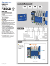
GENERAL OVERVIEW
Product introduction
1
9
11
13
16 17
19
23 67
12
(Position indication I-O-II and product availability outputs)

11
EN
6
7
1
23
Electrical characteristics
Applicable standards and
Terminal incoming and outgoing wiring details.
4. ATYS product current rating and reference number label

12
EN
Environmental
The ATYS product meets the following environmental requirements:
ø 1 mm
Y
correctly installed incoming and outgoing terminal shields.
Operating Conditions
Temperature
Hygrometry
Altitude
Storage Conditions
Temperature
Storage duration period
Storage position

13
EN
Volume and shipping weights by reference ATYS
Frame Size Rating
N° of
Reference
Number
Net Gross
100A
2
6.41
3
10.61
4
200A
2
6.41
3
10.61
4
260A
2
3
12.20
4
14.44
400A
2
3
12.20
4
14.44
UL marking
CE marking
The ATYS complies the with the European directive for:
The ATY

EN
INSTALLATION
L
N
O
C
Y
Y1
H1
H
H
D
H2
JJ1
K
K1
T
21mm
A
Rating Ref. code
ABCDHH1H2YY1
in mm in mm in mm in mm in mm in mm in mm in mm in mm
100 - 200A
97232010 / 97233010 / 97232020 / 97233020
2/3P
12.91 328
6.30 160 9.60 244 0.41 10,5 5.08 129 6.8 173 4.21 107 1.51 38,5 5.21 132,5
97234010 / 97234020
4P
14.88 378
260 - 400A
97232026 / 97233026 / 97232040 / 97233040
2/3P
14.84 377
10.23 260 12.62 320,5 0.41 10,5 8 200 9.7 247 6.53 166 2.04 52 7.48 190
97234026 / 97234040
4P
17.20 437
Rating Ref. code
J J1 K K1 L M N O T
in mm in mm in mm in mm in mm in mm in mm in mm in mm
100 - 200A
97232010 / 97233010 / 97232020 / 97233020
2/3P
6.30 160
1.37 35 7.67 195 3.84 97,5 1.18 30 0.53 13,3 0.98 25 0.43 11 2 50
97234010 / 97234020
4P
8.26 210
260 - 400A
97232026 / 97233026 / 97232040 / 97233040
2/3P
8.26 210
1.37 35 7.67 195 3.84 97,5 1.96 50 0.49 20 1.38 45 0.51 13 2.6 65
97234026 / 97234040
4P
10.63 270
A
C
JJ1
< 79in
K
Door cut-out for front panel.
1.98in
50,5mm
0.78in
20mm
5.43in
138mm
3.97in
101mm
Rating Ref. code
A B C J J1 K K1 K2
in mm in mm in mm in mm in mm in mm in mm in mm
100 - 200A
97232010 / 97233010 / 97232020 / 97233020
2/3P
24 610 24 610 12 305
6.30 160
1.37 35 5.31 135 2.67 68 12 305
97234010 / 97234020
4P 8.26 210
260 - 400A
97232026 / 97233026 / 97232040 / 97233040
2/3P
32 813 32 813 16 406
8.26 210
1.37 35 7.67 195 3.84 97,5 15 381
97234026 / 97234040
4P 10.63 270
K1
K2

EN
Mounting orientation
CAUTION
Always install the product on a flat and rigid surface.
Product mounting lugs
Ø 9mm
Ø 7mm
Assembly of customer mounted accessories
DANGER
Never handle any customer mounted accessories while there may be the risk of
voltage being or becoming present.
O
OFF
-
26 Nm
USED FOR ATYS REF.
26 Nm
Size 17mm

16
EN
13.3 lb-in
1,5 Nm
pozidriv n°1
Ref.
USED FOR
O
OFF
-
O
OFF
-
O
OFF
-
22 lb-in
2,5 Nm
Flat 5
USED FOR

17
EN
2
2
1
1
(fast-on)
Pos II
Pos I
OR
*
General Use 1A
Pos I
Pos II
Pos II
2
2
3
2
Pos I
1
FRAME B4 FRAME B5
100 A 200 A 260 A 400 A
2P 3P 4P 2P 3P 4P 2P 3P 4P 2P 3P 4P
Ref ATYS 97232010 97233010 97234010 97232020 97233020 97234020 97232026 97233026 97234026 97232040 97233040 97234040
Ref lugs 39542020 39543020 39544020 39542020 39543020 39544020 39542040 39543040 39544040 39542040 39543040 39544040
Qty per reference
234234234234
Ref qty to order x3 x3 x3 x3 x3 x3 x3 x3 x3 x3 x3 x3
Désignation
CMC LA300-R CMC LA630-R
Size (AWG) min.
# 6
# 4 1/0
Size (AWG) max.
300 Kcmil
600 Kcmil - 250 Kcmil
Opening per lug
1
1 2
Size of screw
13 17
Torque lb.in / mm
160 / 18
310 / 35
To be connected using terminal lugs, rigid or flexable busbars.

EN
Control circuits
CAUTION
Verify that the nominal auxiliary power supply feeding terminals 301 and 302 are
within the limits of 208VAC -> 277VAC
DANGER
Do not handle any control or power cables connected to the ATYS when voltage
may be present.
Typical ATY
Connect the product with a cable of section of 24 to 16 AWG.
Screw M3 - Tightening torque: min.: 5 lb-in - max. 7 lb-in.
1
2
301 3022
312 313 314 315 316 317 63A 64A 24 14 04 13
Class CC
4A fuse
277VAC
ATS controller
Typical ATY
208VAC
Connect the product with a cable of section of 24 to 16 AWG.
Screw M3 - Tightening torque: min.: 5 lb-in - max. 7 lb-in.
1
2
301 3022
312 313 314 315 316 317 63A 64A 24 14 04 13
Class CC
4A fuse
ATS controller

19
EN
ATYS input and output contacts
Denomination Terminal Description Characteristics Recommended
Cable Section
Signalisation
Outputs
13
2
04
14
24
63A
the ATYS is in Auto mode and motorisation is operational.
(No Fault powered and ready to changeover)
64A
Power supply
Input
301
2
302
Control Inputs 312
Attn:
100m
2
313
input forcing the product to remote control mode
314
316
YS
CAUTION
Do not connect terminals 312 to 317 to any power supply. These order inputs are
powered through terminal 317 and external dry contacts ONLY.

EN
6. ATYS OPERATING MODES
The ATYS includes 3 safe and distinct operating modes through a selector switch located on the front of the product.
As standard the ATYS is delivered with a selector switch however a key lock type selector swith is available on option.
The modes of operation are as follows:
Activates the remote control
inputs.
manual operation handle
when padlocked or when the
handle for manual operation is
inserted into the ATYS.
90°
90°
III
0
AUT
Allows to insert the handle
for manual operation.
(With the handle for
manual operation removed)
Turning the selector switch to
resets a fault state.
3x
Ø 4-8 mm
Ø
0.15-0.31 in
e control inputs.
manual handle.
POS 0
WARNING
a normal operation.
/