
Installation and Commissioning
STEP 1A
Congurator
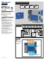
RTSCD
QUICK START
260A, 400A
Non contractual document.
Subject to change without notice.
UL 1008
Preliminary operations
Check the following upon delivery and after removal of
thepackaging:
Packaging and contents are in good condition.
The product reference corresponds to the order.
Contents should include:
Qty 1 x RTCD Transfer switch
Qty 1 x RTSCD Controller
Warning
Risk of electrocution, burns or injury to persons and /
ordamage to equipment.
This Quick Start is intended for personnel trained in
theinstallation and commissioning of this product. For further
details refer to the product instruction manual available
onthe RUSSELECTRIC website.
This product must always be installed and commissioned
by qualified and approved personnel.
Maintenance and servicing operations should be
performed by trained and authorized personnel.
Do not handle any control or power cables connected
tothe product when voltage may be, or may become
present on the product, directly through the mains or
indirectly through external circuits.
Always use an appropriate voltage detection device
toconfirm the absence of voltage.
Ensure that no metal objects are allowed to fall in
thecabinet (risk of electrical arcing).
Failure to observe good engineering practices as well as
tofollow these safety instructions may expose the user and
others to serious injury or death.
Risk of damaging the device
In case the product is dropped or damaged in any way
itis recommended to replace the complete product.
Installation standards must be respected.
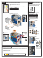
STEP 1
Installation
STEP 2
Controller Interface
STEP 3
Manual Operation
STEP 4
Accessories/
Maintenance
Switch installation
Ensure that the product
is installed on a flat
rigid surface as shown.
All metalic parts must
be grounded
Mounting orientation
548662B
Source 2
Load
Source 1
90E1750003 (548662B)
Model
Operation Type
Switch Type
Operator
Current Rating
Poles
Voltage
Terminal Type
Enclosure Type
Enclosure Rating
PM Power Monitor
AP1: XK1,Load Shed
AP2: XP12,XK12,XP13
RTSCD- A T A
260 3 A M W
3R 1 1 1
A = Automatic
T = Transf er Sw itch
A = LV Open Transition Single Operator
B = LV Open Transition Dual Operator
260 = 260A
400 = 400A
2 =
2 Pole
3 = 3 Pole
4 = 4 Pole
A = 277/480V @ 60Hz
B = 480V @ 60Hz
C = 120/208V @ 60Hz
D = 208V @ 60Hz
E = 120/240V @ 60Hz
F = 240V @ 60Hz
K = 120V @ 60Hz
P = 220/380V @ 50Hz
Q = 380V @ 50Hz
M = Mechanical
W = Wall Mounted
OV = Open Style Verticle
OH = Open Style Horizontal
1 = Type
1
3R = Typ e 3R
0
= Not Included
1 = Included

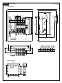
STEP 1B
12
305
18.31
465
5.7
144,8
14.92
379
7.13
181
min. 2.75
min. 70
Max. 14
Max. 355,6
Min. 13.3
Min. 338
4.23
107,5
L
2.02
51,4
8.01
203,4
1.77
45
P1.55
39,3
24
610
48
1219
9.45
240
2.52
63,90
1.89
48,10
7.09
180
6.30
160
8.66
220
A
3.93
99,8
1.56
39,7
4.64
117,7
2.27
57,6
Products dimensions
Switch dimensions
Controller dimensions
Dual Dimensions
in/mm
A L P
in mm in mm in mm
2P 11.67 296,30 5 128,60 1.97 50
3P 13.63 346,30 7 178,60 1.97 50
4P 15.60 396,30 9 228,60 1.97 50

STEP 1C
STEP 1D
Gasket for NEMA 3R/12
Mount the load terminal lugs on the switch terminals before mounting source 2 terminal lugs.
1
2
Mounting & connecting controller
Installing terminal lugs (optional accessory)
Door mounting
Backplate mounting
Use terminal screws and washers supplied with the ATSE
Product
Rating (A)
Designation Ref. lugs
Quantity per
reference
Openings
per lug
Size Pressure screw torque Bolt torque
Y
min. max. lb.in Nm Size in lb.in Nm Size in mm
260-400 A
CMC LA-630R
39023040
6
1
2
4
1/0
600 KCMIL
250 KCMIL
550 62,1 1/2 310 35 8 mm 1.79 45,739543040
9
39544040
12
260-400 A
Ilsco D3096
39012040 6
1
2
4
1/0
600 KCMIL
250 KCMIL
600 67,8 1/2 310 35
8 mm 1.79 45,739013040 9
39014040 12
Power cable connections :
- for 260A use 300 Kcmil copper cables
- for 400A use 600 Kcmil copper cables
Screw Tightening torque
PH1 / 0.2 Nm / 1.77 lb.in
Screws notdelivered with product
8.66
+/-0.4
220
+/-1
6.30
+/-0.4
160
+/-1
5.9
+/-0.4
150
+/-1
6.77 - 7
172 - 178
Insert the 4 door
mounting screws in
thedesignated slot and
push back to clip in lock
in place.
Example of cable way.
Clip the mounting feet in
thedesignated slot
GND
GND
0.25
6,4
R 0.24
R 6,25
Ø 0.21
Ø 5,5
0.12
3
0.30
±0,007
7,7
±0,2
1.53
±0,01
39
±0,3
0.86
22,05
0.05
±0,02
15,5
±0,5
135°
0.07
2
0.31
±
0,004
8
±0,1

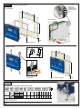
STEP 2
STEP 3
Inspection of power contacts
Controller Interface
Manual operation (for maintenance purpuses only)
Instructions for manual, non electric, offload operations for service
Switch will be “not in auto” whencover is open.
WARNING
More than one live circuit, disconnect all sources of supply before servicing and/or before using the manual operation.
WARNING
LCD display
Source and
switchsynoptic
Manual operation
buttons and indicator
Communication
indicator LED
Switch not in automatic
mode indicator LED
Automatic button
and LED
indicator
Test button and indicator
Lamp test button
Power, Fault and
alarm LED
Navigation
buttons
Change dashboard / set screen
as favorite
Clip to maintain cover
upright
Unscrew to open
and inspect arc
chutes and contacts
Slide cover to
access service
handle hole.
For inspection use
a standard tool as
shown to operate
(not included).
6 mm diam.
0.25" max.
SLOW OPERATION
3
2
4
1
A
A
B C
C
B
Tightening torque
17.7 lb.in / 2 N.m / PH2
Tightening torque
17.7 lb.in / 2 N.m / PH2
For manual operation
operate handle:
up from S2 to S1
down from S1 to S2
FAST OPERATION
Recommendation : carry out one offload manual operation with
handle before putting the switch back in service.
Reverse the procedure to close.
Ensure that all is closed properly before putting back in service.
In case any part of the RTSCD switch is found to be damaged in any way, replace the complete switch.

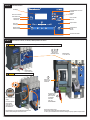
STEP 4A
PERIODIC MAINTENANCE
Installing power terminal shrouds (optional accessories)
Additional auxiliary contacts
Assemble optional aux contact and
pre-installed aux contact together
Auxiliary contact electrical characteristics
Switch has 2 pre-installed auxilliary contact, the kit below is
for 2 additionnal with protection against direct contact.
For 600 KCMIL wires remove marked (*) parts.
Terminal shrouds can be
locked in place using
locking points
The RTSCD shall be maintained in accordance with industry standards and as per instructions in the RTSCD instruction sheet.
As per NFPA 110 requirements for emergency and standby power systems the RTSCD should be inspected and should be
exercised under load at least monthly.
Refer to step 5 for instructions for manual, non electric, offload operations for service.
Terminal shrouds contain
provisions for voltage
sensing
Fix the terminal shourds in place and
push back
Remove pre-installed
auxillarycontact
Assemble contacts with parts from
kit as shown below
Push back to click
in place.
Ref : 96990021
1
2
a
3
b
PH2 screwdriver
Tightening torque
17.7 lb.in / 2 N.m / PH2
Make sure, contact is
correctly activated
Rated current (125-480 VAC) 22 A
Rated current (125 VDC) 0.5A
Rated current (250 VDC) 0.25 A
Rated horse power up to 250 VAC ½ HP
Rated horse power up to 480 VAC ¼ HP
Recommended wire section
4 mm²
10 AWG
Terminal tightening torque
7.9 lb.in / 0.9 Nm
1
1
NO NC
COM
2
2
3
3
Top and bottom protection against direct contact with terminals or connecting parts
No. of poles Reference*
2P 96982020
3P/2P+N 96983020
4P/3P+N 96984020
* Refs: top and bottom
3
2
1
STEP 4B
V
More than one live circuit disconnect all sources of supply before servicing and/or before
using the manual operation.
WARNING
*
-
 1
1
-
 2
2
-
 3
3
-
 4
4
-
 5
5


Ask a question and I''ll find the answer in the document
Finding information in a document is now easier with AI
Other documents
-
Socomec ATyS UL Quick Start
-
Socomec ATyS r - ATyS d Operating instructions
-
-
-
-
 Phoenix Gold ZDSKI1 Installation guide
-
-
-
-
