Page is loading ...

OPER ATOR'S MANUAL
DISC HARROW
MAN1106
(Rev. 9/1/2015)
DHH108T
DHH126T
DHH144T

2 Introduction
Gen’l (Rev. 12/5/2011)
TO THE DEALER:
Assembly and proper installation of this product is the responsibility of the Woods
®
dealer. Read manual instructions
and safety rules. Make sure all items on the Dealer’s Pre-Delivery and Delivery Check Lists in the Operator’s Manual
are completed before releasing equipment to the owner.
The dealer must complete the online Product Registration form at the Woods Dealer Website which certifies that
all Dealer Check List items have been completed. Dealers can register all Woods product at
dealer.WoodsEquipment.com under Product Registration.
Failure to register the product does not diminish customer’s warranty rights.
TO THE OWNER:
Read this manual before operating your Woods equipment. The information presented will prepare you to do a better and
safer job. Keep this manual handy for ready reference. Require all operators to read this manual carefully and become
acquainted with all adjustment and operating procedures before attempting to operate. Replacement manuals can be
obtained from your dealer. To locate your nearest dealer, check the Dealer Locator at www.WoodsEquipment.com, or in
the United States and Canada call 1-800-319-6637.
The equipment you have purchased has been carefully engineered and manufactured to provide dependable and
satisfactory use. Like all mechanical products, it will require cleaning and upkeep. Lubricate the unit as specified.
Observe all safety information in this manual and safety decals on the equipment.
For service, your authorized Woods dealer has trained mechanics, genuine Woods service parts, and the necessary
tools and equipment to handle all your needs.
Use only genuine Woods service parts. Substitute parts will void the warranty and may not meet standards required for
safe and satisfactory operation. Record the model number and serial number of your equipment in the spaces
provided:
Model:
_______________________________
Date of Purchase:
_____________________
Serial Number:
(see Safety Decal section for location) ____________________________________
Provide this information to your dealer to obtain correct repair parts.
Throughout this manual, the term NOTICE is used to indicate that failure to observe can cause damage to equipment.
The terms CAUTION, WARNING, and DANGER are used in conjunction with the Safety-Alert Symbol (a triangle with
an exclamation mark) to indicate the degree of hazard for items of personal safety.

Introduction 3
MAN1106 (10/10/2014)
TABLE OF CONTENTS
INTRODUCTION . . . . . . . . . . . . . . . . . . . . . . . . . . . . . . . . . . . . . . . . . . . . . . 2
SPECIFICATIONS. . . . . . . . . . . . . . . . . . . . . . . . . . . . . . . . . . . . . . . . . . . . . 4
GENERAL INFORMATION . . . . . . . . . . . . . . . . . . . . . . . . . . . . . . . . . . . . . . 4
SAFETY RULES . . . . . . . . . . . . . . . . . . . . . . . . . . . . . . . . . . . . . . . . . . . . . . 5
SAFETY DECALS . . . . . . . . . . . . . . . . . . . . . . . . . . . . . . . . . . . . . . . . . . . . . 8
OPERATION . . . . . . . . . . . . . . . . . . . . . . . . . . . . . . . . . . . . . . . . . . . . . . . . 10
SERVICE . . . . . . . . . . . . . . . . . . . . . . . . . . . . . . . . . . . . . . . . . . . . . . . . . . . 15
ASSEMBLY INSTRUCTIONS . . . . . . . . . . . . . . . . . . . . . . . . . . . . . . . . . . . 18
DEALER CHECK LISTS . . . . . . . . . . . . . . . . . . . . . . . . . . . . . . . . . . . . . . . 21
PARTS INDEX . . . . . . . . . . . . . . . . . . . . . . . . . . . . . . . . . . . . . . . . . . . . . . . 22
BOLT TORQUE CHART . . . . . . . . . . . . . . . . . . . . . . . . . . . . . . . . . . . . . . . 31
BOLT SIZE CHART & ABBREVIATIONS . . . . . . . . . . . . . . . . . . . . . . . . . . 32
REPLACEMENT PARTS WARRANTY . . . . . . . . . . . . . . . . . . . . . . . . . . . . 34
PRODUCT WARRANTY . . . . . . . . . . . . . . . . . . . . . . . INSIDE BACK COVER

4 Introduction
MAN1106 (10/10/2014)
SPECIFICATIONS
GENERAL INFORMATION
The purpose of this manual is to assist you in operating
and maintaining your Disc Harrow. Read it carefully. It
furnishes information and instructions that will help you
achieve years of dependable performance.
These instructions have been compiled from extensive
field experience and engineering data. Some informa-
tion may be general in nature, due to unknown and
varying operating conditions. However, through experi-
ence and these instructions, you should be able to
develop procedures suitable to your particular situa-
tion.
The illustrations and data used in this manual were cur-
rent at the time of printing. However, due to possible
inline production changes, your machine may vary
slightly in detail. We reserve the right to redesign and
change the machines as may be necessary without
notification.
Throughout this manual, references are made to right
and left direction. These are determined by standing
behind the tractor facing the direction of forward travel.
DHH108T DHH126T DHH144T
Working Width 108 inches 126 inches 144 inches
Weight 2590 lbs. 2770 lbs. 2950 lbs.
Number of Blades 24 28 32
Weight per Blade 108 lbs. 93 lbs. 81 lbs.
Horsepower 50 - 75 60 - 100 70 - 110
Hitch Pull-type, 1-1/4" Pin Pull-type, 1-1/4" Pin Pull-type, 1-1/4"Pin
Angling Front & Rear Front & Rear Front & Rear
0 - 21 degrees 0 - 21 degrees 0 - 21 degrees
(7 positions) (7 positions) (7 positions)
Blade Type Notched or Smooth Notched or Smooth Notched or Smooth
Blade Diameter 20" or 22" 20" or 22" 20" or 22"
Blade Spacing 9 inches 9 inches 9 inches
Axle Diameter 1-1/8" Square 1-1/8" Square 1-1/8" Square
Bearing Type Greaseable, Self-Aligning Greaseable, Self-Aligning Greaseable, Self-Aligning
Bearing Hangers Dual, 1/2" Plate, U-Bolt Triple, 1/2" Plate, U-Bolt Triple, 1/2" Plate, U-Bolt
U-Bolts Single, 3/4" Single, 3/4" Single, 3/4"
Frame Tube 4" x 3" 4" x 3" 4" x 3"
Disc Gang Tube 4" x 3" 4" x 3" 4" x 3"
Tire Size
9.5L x 15" Ag or 29" Used Aircraft 9.5L x 15" Ag or 29" Used Aircraft 9.5L x 15" Ag or 29" Used Aircraft
Single or Dual Single or Dual Single or Dual
Accessories Mud Scrapers, Furrow Fillers,
Rear Drawbar
Mud Scrapers, Furrow Fillers,
Rear Drawbar
Mud Scrapers, Furrow Fillers,
Rear Drawbar

Safety 5
DHH Disc Harrow (9/29/2014)
INSTALLATION
Hydraulics must be connected as instructed in
this manual. Do not substitute parts, modify, or
connect in any other way.
TRAINING
Safety instructions are important! Read all
attachment and power unit manuals; follow all
safety rules and safety decal information. (Replace-
ment manuals and safety decals are available from
your dealer. To locate your nearest dealer, check
the Dealer Locator at www.WoodsEquipment.com,
or in the United States and Canada call 1-800-319-
6637.) Failure to follow instructions or safety rules
can result in serious injury or death.
If you do not understand any part of this manual
and need assistance, see your dealer.
Operators must be instructed in and be capable
of the safe operation of the equipment, its attach-
ments, and all controls. Do not allow anyone to
operate this equipment without proper instructions.
Never allow children or untrained persons to
operate equipment.
Keep hands and body away from pressurized
lines. Use paper or cardboard, not hands or other
body parts to check for leaks. Wear safety goggles.
Hydraulic fluid under pressure can easily penetrate
skin and will cause serious injury or death.
Make sure that all operating and service person-
nel know that if hydraulic fluid penetrates skin, it
must be surgically removed as soon as possible by
a doctor familiar with this form of injury or gan-
grene, serious injury, or death will result. CON-
TACT A PHYSICIAN IMMEDIATELY IF FLUID
ENTERS SKIN OR EYES. DO NOT DELAY.
PREPARATION
Check that all hardware is properly installed.
Always tighten to torque chart specifications
unless instructed otherwise in this manual.
Air in hydraulic systems can cause erratic oper-
ation and allows loads or equipment components
to drop unexpectedly. When connecting equipment
or hoses or performing any hydraulic maintenance,
purge any air in hydraulic system by operating all
hydraulic functions several times. Do this before
putting into service or allowing anyone to
approach the equipment.
Make sure all hydraulic hoses, fittings, and
valves are in good condition and not leaking before
starting power unit or using equipment. Check and
route hoses carefully to prevent damage. Hoses
must not be twisted, bent sharply, kinked, frayed,
pinched, or come into contact with any moving
parts. Operate moveable components through full
operational range to check clearances. Replace
any damaged hoses immediately.
After connecting hoses, check that all control
lever positions function as instructed in the Opera-
tor's Manual. Do not put into service until control
lever and equipment movements are correct.
Your dealer can supply original equipment
hydraulic accessories and repair parts. Substitute
parts may not meet original equipment specifica-
tions and may be dangerous.
Set tractor hydraulic relief valve at 2500 psi (170
bars) (17,000 kPa) to prevent injury and equipment
damage due to hydraulic system failure.
Remove accumulated debris from this equip-
ment, power unit, and engine to avoid fire hazard.
Make sure all safety decals are installed.
Replace if damaged. (See Safety Decals section for
location.)
Always wear relatively tight and belted clothing
to avoid getting caught in moving parts. Wear
sturdy, rough-soled work shoes and protective
equipment for eyes, hair, hands, hearing, and head;
and respirator or filter mask where appropriate.
Make sure attachment is properly secured,
adjusted, and in good operating condition.
Power unit must be equipped with ROPS or
ROPS cab and seat belt. Keep seat belt securely
fastened. Falling off power unit can result in death
from being run over or crushed. Keep foldable
ROPS system in “locked up” position at all times.
(Safety Rules continued on next page)
Safety is a primary concern in the design and
manufacture of our products. Unfortunately, our
efforts to provide safe equipment can be wiped
out by an operator’s single careless act.
In addition to the design and configuration of
equipment, hazard control and accident preven-
tion are dependent upon the awareness, con-
cern, judgement, and proper training of
personnel involved in the operation, transport,
maintenance, and storage of equipment.
It has been said, “The best safety device is an
informed, careful operator.” We ask you to be
that kind of operator.
SAFETY RULES
ATTENTION! BECOME ALERT! YOUR SAFETY IS INVOLVED!

6 Safety
DHH Disc Harrow (9/29/2014)
(Safety Rules continued from previous page)
A minimum 20% of tractor and equipment
weight must be on the tractor front wheels when
attachments are in transport position. Without this
weight, front tractor wheels could raise up result-
ing in loss of steering. The weight may be attained
with front wheel weights, ballast in tires or front
tractor weights. Weigh the tractor and equipment.
Do not estimate.
Consult local utilities before working. Know
location of all underground cables, pipelines, over-
head wires, and other hazards in working area and
avoid contact.
TRANSPORTATION
Power unit must be equipped with ROPS or
ROPS cab and seat belt. Keep seat belt securely
fastened. Falling off power unit can result in death
from being run over or crushed. Keep foldable
ROPS system in “locked up” position at all times.
Always raise unit and install transport locks
before transporting. Leak down or failure of
mechanical or hydraulic system can cause equip-
ment to drop.
Always attach safety chain to tractor drawbar
when transporting unit.
The maximum transport speed for towed and semi-
mounted machines is 20 mph (32 km/h). Regardless of
the maximum speed capability of the towing tractor, do
not exceed the implement’s maximum transport speed.
Doing so could result in:
• Loss of control of the implement and tractor
• Reduced or no ability to stop during braking
• Implement tire failure
• Damage to the implement or its components.
Use additional caution and reduce speed when
under adverse surface conditions, turning, or on
inclines.
Never tow this implement with a motor vehicle.
Always comply with all state and local lighting
and marking requirements.
Never allow riders on power unit or attachment.
Do not operate or transport on steep slopes.
Use extreme care and reduce ground speed on
slopes and rough terrain.
Do not operate or transport equipment while
under the influence of alcohol or drugs.
OPERATION
Do not allow bystanders in the area when oper-
ating, attaching, removing, assembling, or servic-
ing equipment.
Do not operate or transport equipment while
under the influence of alcohol or drugs.
Always comply with all state and local lighting
and marking requirements.
Operate only in daylight or good artificial light.
Keep hands, feet, hair, and clothing away from
equipment while engine is running. Stay clear of all
moving parts.
Never allow riders on power unit or attachment.
Power unit must be equipped with ROPS or
ROPS cab and seat belt. Keep seat belt securely
fastened. Falling off power unit can result in death
from being run over or crushed. Keep foldable
ROPS system in “locked up” position at all times.
Always sit in power unit seat when operating
controls or starting engine. Securely fasten seat
belt, place transmission in neutral, engage brake,
and ensure all other controls are disengaged
before starting power unit engine.
Look down and to the rear and make sure area
is clear before operating in reverse.
Use extreme care when working close to fences,
ditches, other obstructions, or on hillsides.
Do not operate or transport on steep slopes.
Do not stop, start, or change directions sud-
denly on slopes.
Use extreme care and reduce ground speed on
slopes and rough terrain.
Stop power unit and equipment immediately
upon striking an obstruction. Turn off engine,
remove key, inspect, and repair any damage before
resuming operation.
Watch for hidden hazards on the terrain during
operation.
(Safety Rules continued on next page)
SAFETY RULES
ATTENTION! BECOME ALERT! YOUR SAFETY IS INVOLVED!

Safety 7
DHH Disc Harrow (9/29/2014)
(Safety Rules continued from previous page)
MAINTENANCE
Before servicing, adjusting, repairing or unplug-
ging, stop tractor engine, place all controls in neu-
tral, set park brake, remove ignition key.
Before dismounting power unit or performing
any service or maintenance, follow these steps:
disengage power to equipment, lower the 3-point
hitch and all raised components to the ground,
operate valve levers to release any hydraulic pres-
sure, set parking brake, stop engine, remove key,
and unfasten seat belt.
Always wear relatively tight and belted clothing
to avoid getting caught in moving parts. Wear
sturdy, rough-soled work shoes and protective
equipment for eyes, hair, hands, hearing, and head;
and respirator or filter mask where appropriate.
Never go underneath equipment (lowered to the
ground or raised) unless it is properly blocked and
secured. Never place any part of the body under-
neath equipment or between moveable parts even
when the engine has been turned off. Hydraulic
system leak down, hydraulic system failures,
mechanical failures, or movement of control levers
can cause equipment to drop or rotate unexpect-
edly and cause severe injury or death.
Make sure attachment is properly secured,
adjusted, and in good operating condition.
Never perform service or maintenance with
engine running.
Keep all persons away from operator control
area while performing adjustments, service, or
maintenance.
Tighten all bolts, nuts, and screws to torque
chart specifications. Check that all cotter pins are
installed securely to ensure equipment is in a safe
condition before putting unit into service.
Do not modify or alter or permit anyone else to
modify or alter the equipment or any of its compo-
nents in any way.
Your dealer can supply original equipment
hydraulic accessories and repair parts. Substitute
parts may not meet original equipment specifica-
tions and may be dangerous.
To prevent contamination during maintenance
and storage, clean and then cover hose ends, fit-
tings, and hydraulic ports with tape.
Do not allow bystanders in the area when oper-
ating, attaching, removing, assembling, or servic-
ing equipment.
Make sure all safety decals are installed.
Replace if damaged. (See Safety Decals section for
location.)
Do not disconnect hydraulic lines until machine
is securely blocked and system pressure is
released by operating valve levers.
Explosive separation of tire and rim parts can
cause serious injury or death. Release all air pres-
sure before loosening bolts on wheel.
STORAGE
To help prevent injury caused by a falling imple-
ment, always detach on a hard level surface.
Block equipment securely for storage.
Remove hydraulic hoses only after tractor is
turned off and all system pressure is released by
operating valve levers several times.
Keep children and bystanders away from stor-
age area.
Follow manual instructions for storage.
SAFETY RULES
ATTENTION! BECOME ALERT! YOUR SAFETY IS INVOLVED!

8 Safety
MAN1106 (10/10/2014)
BE CAREFUL!
Use a clean, damp cloth to clean safety decals.
Avoid spraying too close to decals when using a pressure
washer; high-pressure water can enter through very small
scratches or under edges of decals causing them to peel
or come off.
Replacement safety decals can be ordered free from your
Woods dealer. To locate your nearest dealer, check the
Dealer Locator at www.WoodsEquipment.com, or in the
United States and Canada call 1-800-319-6637.
1 - SERIAL NUMBER PLATE
SAFETY & INSTRUCTIONAL DECALS
ATTENTION! BECOME ALERT! YOUR SAFETY IS INVOLVED!
Replace Immediately If Damaged!

Safety 9
MAN1106 (10/10/2014)
5 - PN 19924
2 - PN 1003751
3 - PN 1004991
4 - PN 18865
7 - FRONT AMBER REFLECTOR (PN 1002940) Located on front of all gang tubes.
8 - REAR RED REFLECTOR (PN 57123) Located on rear of all gang tubes.
9 - SMV SIGN (PN 24611) (Not shown).
PN 1006348 - Located on Wheel Rims
6 - PN 55122
SAFETY & INSTRUCTIONAL DECALS
ATTENTION! BECOME ALERT! YOUR SAFETY IS INVOLVED!
Replace Immediately If Damaged!

10 Operation
MAN1106 (10/10/2014)
OPERATION
The operator is responsible for the safe operation of
this equipment. The operator must be properly trained.
Operators should be familiar with the equipment, the
tractor, and all safety practices before starting opera-
tion. Read the safety rules and safety decals, page 5
through page 7.
The Disc Harrow is designed for a wide range of appli-
cations: leveling, grading, and discing. Recommended
tractor ground speed for most conditions is from 2 to 7
mph.
A minimum 20% of tractor and equipment
weight must be on the tractor front wheels when
attachments are in transport position. Without this
weight, front tractor wheels could raise up result-
ing in loss of steering. The weight may be attained
with front wheel weights, ballast in tires or front
tractor weights. Weigh the tractor and equipment.
Do not estimate.
Power unit must be equipped with ROPS or
ROPS cab and seat belt. Keep seat belt securely
fastened. Falling off power unit can result in death
from being run over or crushed. Keep foldable
ROPS system in “locked up” position at all times.
Never allow children or untrained persons to
operate equipment.
Do not allow bystanders in the area when oper-
ating, attaching, removing, assembling, or servic-
ing equipment.
NEVER GO UNDERNEATH EQUIPMENT. Never
place any part of the body underneath equipment
or between moveable parts even when the engine
has been turned off. Hydraulic system leak-down,
hydraulic system failures, mechanical failures, or
movement of control levers can cause equipment
to drop or rotate unexpectedly and cause severe
injury or death.
• Service work does not require going under-
neath implement.
• Read Operator's Manual for service instruc-
tions or have service performed by a qualified
dealer.
Keep hands, feet, hair, and clothing away from
equipment while engine is running. Stay clear of all
moving parts.
Stop power unit and equipment immediately
upon striking an obstruction. Turn off engine,
remove key, inspect, and repair any damage before
resuming operation.
Always wear relatively tight and belted clothing
to avoid getting caught in moving parts. Wear
sturdy, rough-soled work shoes and protective
equipment for eyes, hair, hands, hearing, and head;
and respirator or filter mask where appropriate.
PRE-OPERATION CHECK LIST
(Owner’s Responsibility)
___ Review and follow all safety rules and safety
decal instructions, page 5 through page 9.
___ Check all lubrication points and grease as
instructed in lubrication information.
___ Check that all hydraulic hoses and fittings are
in good condition and not leaking before start-
ing tractor. Check that hoses are not twisted,
bent sharply, kinked, frayed, or pulled tight.
Replace any damaged hoses immediately.
___ Raise and lower equipment to make sure air is
purged from hydraulic cylinders and hoses.
___ Make sure tractor 3-point lift links do not inter-
fere with hydraulic hoses or driveline through-
out full turning range.
___ Check that equipment is properly and securely
attached to tractor.
___ Check that all safety decals are installed and in
good condition. Replace if damaged.
___ Check that all hardware is properly installed
and secured.
___ Do not allow riders.
___ Make sure tractor ROPS or ROPS cab and
seat belt are in good condition. Keep seat belt
securely fastened during operation.
CAUTION

Operation 11
MAN1106 (10/10/2014)
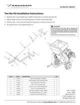
CONNECT DISC HARROW TO TRACTOR
This Disc Harrow should be pulled behind tractors
within the engine horsepower rating specified on page
4. Do not exceed maximum engine horsepower rating
for a given model.
1. Attach Disc Harrow to drawbar using a 1-1/8"
clevis pin and clip.
2. Attach safety tow chain (7) to drawbar support.
Leave enough slack for turning. (See Figure 1).
3. Remove pin and rotate parking jack (6) to
horizontal position on tongue. Secure parking jack
with pin for storage during operation.
Figure 1. Connect Disc Harrow to Tractor
Lighting Connection (If Equipped)
1. Inspect wiring harnesses and connections to
ensure they are in good condition.
2. Route wiring harness (2) through hose holder (3) at
the hitch and be sure the harness can slide freely
in the holder. Do not allow wiring harness slack to
drag on the ground or become caught on tractor
protrusions.
3. Attach the wiring harness to the tractor.
Hydraulic Connection
1. Inspect hydraulic hoses to ensure they are in good
condition.
2. Clean the fittings before connecting them to the
tractor hydraulic ports.
3. Route the hoses through the hose holder at the
hitch and be sure the hoses can slide freely in the
holder. Do not allow hose slack to drag on the
ground or become caught on tractor protrusions.
4. Attach the hydraulic hoses to the tractor.
5. From the operator position, start tractor and raise
and lower Disc Harrow several times to purge
trapped air from the hydraulic cylinder.
Interference Check
1. Be sure that tractor 3-point lift links do not interfere
with hydraulic hoses or disc harrow frame.
2. Check for straight-ahead operation and at full
turning angles. If here is any interference, remove
the lower lift links.
3. Contact between tractor lift links and disc harrow
parts can cause damage, especially when turning.
DISC HARROW ATTITUDE ADJUSTMENT
For best results, always maintain a level disc attitude. A
level disc attitude will leave a slight ridge of material, in
the center, behind the rear gangs. A large ridge of
material will require the attitude to be adjusted forward.
a furrow, in the center, behind the rear gangs will
require the attitude to be adjusted to the rear. Attitude
adjustments can be made, while the disc harrow is con-
nected to the tractor, by following these instructions:
Forward Attitude Adjustment
(Shorten the Ratchet Jack)
1. Raise Disc Harrow to full height and secure with
transport lock.
2. Rotate ratchet jack (8) clockwise to adjust attitude
forward.
3. Release transport lock and resume operation.
check for proper attitude adjustment and repeat as
necessary.
Rear Attitude Adjustment
(Lengthen the Ratchet Jack)
1. Raise Disc Harrow to full height and secure with
transport lock.
2. Rotate ratchet jack counter-clockwise to adjust
attitude to the rear.
3. Release transport lock and resume operation.
Check for proper attitude adjustment and repeat as
necessary.
NOTICE
■
Excessive forward or rear attitude adjustment
will lead to poor finish and may cause equipment
damage or premature bearing failure.

12 Operation
MAN1106 (10/10/2014)
Note: Disc Harrow attitude should only be adjusted
using the ratchet jack. For instructions on adjusting atti-
tude rod spring tension, see ATTITUDE ROD ADJUST-
MENT.
Figure 2. Disc Harrow Attitude Adjustment
ATTITUDE ROD ADJUSTMENT
A properly adjusted attitude rod will have a snug, but
not compressed, rear coil spring when the Disc Harrow
is in transport mode. Adjustments can be made, by fol-
lowing these instructions.
1. Raise Disc Harrow to full height and secure with
transport lock.
2. Loosen outer nut (9) to allow adjustment.
3. If rear spring (5) is loose, tighten inner nut (9) until
spring is snug.
4. If rear spring is compressed, loosen inner nut until
spring is snug.
5. Tighten outer nut while retaining inner nut to lock
adjustment.
Figure 3. Attitude Rod Adjustment
ANGLING DISC BLADES
All disc gangs are fully adjustable with 7 positions
between 0 and 21 degrees. The disc setting becomes
more aggressive with increased gang angle. The
greater the disc angle, the greater the material turn
over. Adjustments can be made to the disc gang
angles by following these instructions:
1. Raise Disc Harrow until blades are just off the
ground.
2. Remove klik pin (6) from lock plate (4).
3. Pull lock plate up and lock in place with klik pin.
4. Grasp lock plate and handle (5) and slide carriage
to desire position.
5. Hold lock plate and remove klik pin.
6. Push lock plate down in new position and secure
with klik pin.
7. Repeat for remaining disc gangs.
Figure 4. Angling Disc Blades
NOTICE
■
Although front and rear gang sets can be
adjusted independently, right and left gangs
should always be adjusted to the same angle by
not allowing open positions between carriages.

Operation 13
MAN1106 (10/10/2014)
ADJUSTING DISC OPERATING DEPTH
The operating depth of the Disc Harrow is controlled by
installing stroke control spacers on the hydraulic cylin-
der rod. A cylinder stroke control kit is included with the
Disc Harrow. The operating depth of the Disc Harrow
can be set by following these instructions:
1. Operate the Disc Harrow with all spacers removed.
make adjustments to the hydraulic cylinder until the
desired operating depth is achieved.
2. Stop tractor, set parking brake, stop engine,
remove key, and unfasten seat belt.
3. Measure amount of exposed cylinder rod and
select required spacers (27).
4. Return to tractor, extend hydraulic cylinder to
maximum length. Stop engine, remove key.
5. Install selected spacers on cylinder rod. keep
remaining spacers installed on wheel arm (1) for
future use.
6. Return to tractor, lower cylinder against spacers.
Continue operation.
7. Check that desired operating depth was achieved.
Repeat steps as necessary to achieve desired
depth.
NOTE: Spacer sizes required will depend on tire
type and size installed on disc.
Figure 5. Adjusting Disc Operating Depth
STORAGE
To help prevent injury caused by a falling imple-
ment, always detach on a hard level surface.
Block equipment securely for storage.
Remove hydraulic hoses only after tractor is
turned off and all system pressure is released by
operating valve levers several times.
Keep children and bystanders away from stor-
age area.
Follow manual instructions for storage.
Disc Harrow should be stored with disc blades lowered
to the ground after each use. Disconnect the Disc Har-
row by following these instructions:
1. Lower Disc Harrow to ground.
2. Securely block in front of and behind wheels to
prevent wheel rotation.
3. Attach parking jack and raise tongue weight off
tractor drawbar.
4. Remove hydraulic hoses only after tractor is turned
off and all system pressure is released by
operating valve levers several times. Hang hoses
in hose holder on disc hitch.
5. Remove wiring harness (if equipped) and hang on
hose holder.
6. Remove safety tow chain.
7. Remove retainer pin and high strength drawbar
pin.
TRANSPORTING
Power unit must be equipped with ROPS or
ROPS cab and seat belt. Keep seat belt securely
fastened. Falling off power unit can result in death
from being run over or crushed. Keep foldable
ROPS system in “locked up” position at all times.
Always raise unit and install transport locks
before transporting. Leak down or failure of
mechanical or hydraulic system can cause equip-
ment to drop.
Always attach safety chain to tractor drawbar
when transporting unit.
Never exceed 20 mph (32.2 km/h) during trans-
port.
Never allow riders on power unit or attachment.
Do not operate or transport on steep slopes.
Do not operate or transport equipment while
under the influence of alcohol or drugs.
Use additional caution and reduce speed when
under adverse surface conditions, turning, or on
inclines.
■
Never tow this implement with a motor vehicle.

14 Operation
MAN1106 (10/10/2014)
Always comply with all state and local lighting
and marking requirements.
Figure 6. Transport Lock - Transport Position
Lock-Up
Always transport the Disc Harrow in the raised, locked
position.
1. Raise Disc Harrow with hydraulic cylinder to
maximum height.
2. Rotate transport lock (2) into position over cylinder
rod. (See Figure 6).
3. Lower disc harrow against transport lock.
4. To lower Disc Harrow for operation, extend
hydraulic cylinder to release transport lock. Rotate
transport lock away from cylinder rod. (See Figure
7).
5. Lower disc to desired operating height.
Figure 7. Transport Lock - Operating Position
CAUTION

Service 15
MAN1106 (10/10/2014)
SERVICE
The information in this section is written for operators
who possess basic mechanical skills. If you need help,
your dealer has trained service technicians available.
For your protection, read and follow the safety informa-
tion in this manual.
Before servicing, adjusting, repairing or unplug-
ging, stop tractor engine, place all controls in neu-
tral, set park brake, remove ignition key, and wait
for all moving parts to stop.
Never perform service or maintenance with
engine running.
NEVER GO UNDERNEATH EQUIPMENT. Never
place any part of the body underneath equipment
or between moveable parts even when the engine
has been turned off. Hydraulic system leak-down,
hydraulic system failures, mechanical failures, or
movement of control levers can cause equipment
to drop or rotate unexpectedly and cause severe
injury or death.
• Service work does not require going under-
neath.
• Read Operator's Manual for service instruc-
tions or have service performed by a qualified
dealer.
Keep all persons away from operator control
area while performing adjustments, service, or
maintenance.
Always wear relatively tight and belted clothing
to avoid getting caught in moving parts. Wear
sturdy, rough-soled work shoes and protective
equipment for eyes, hair, hands, hearing, and head;
and respirator or filter mask where appropriate.
If you do not understand any part of this manual
and need assistance, see your dealer.
LUBRICATION
Do not let excess grease collect on or around parts,
particularly when operating in sandy areas.
See Figure 8 for lubrication points and frequency for
lubrication based on normal operating conditions.
Severe or unusual conditions may require more fre-
quent lubrication.
Use a lithium grease of #2 consistency with a MOLY
(molybdenum disulfide) additive for all locations. Be
sure to clean fittings thoroughly before attaching
grease gun. One good pump of most guns is sufficient
when lubrication schedule is followed.
Figure 8. Lubrication Points
NOTICE
■
Do not use excessive amounts of grease on
bearings (5). Excessive amounts of grease can
cause seal damage and/or premature bearing fail-
ure.
DISC & BEARING REPLACEMENT
Disassemble Gang
1. Lower Disc Harrow to ground.
2. Securely block front and rear wheels to prevent
wheel rotation.
CAUTION
1. Hitch pivot points . . . . . . . . . 40 hrs.
2. Attitude rod . . . . . . . . . . . . . 20 hrs.
3. Wheel bearings . . . . . . . . . . 20 hrs.
4. Wheel mount pivot points . . 40 hrs.
5. Disc gang axle bearings . . . 80 hrs.

16 Service
MAN1106 (10/10/2014)
3. Remove carriage bolts (9) and nuts (10) from all
bearings on disc harrow gang.
4. Remove gang assembly from bearing hangers by
raising Disc Harrow to full height. Secure with
transport lock.
5. With gang assembly removed from bearing
hangers, remove outer and inner jam nuts (18),
axle washer (14) and end spacer (17).
6. Slide discs, spacers, washer and bearings off axle
as needed to replace desired disc(s) and
bearing(s).
NOTE: Maintain proper order of discs, spacers,
washers and bearings for reassembly. (See Parts
page 25).
Figure 9. Disc Gang Assembly
Assemble Gang
1. Reassemble gang with new disc(s) and bearing(s)
in reverse order of disassembly steps.
NOTE: Maintain proper order of discs, spacers,
and bearings for reassembly. (See Parts page 25).
2. Install end spacer, axle washer and inner jam nut.
Torque inner jam nut to 450 lbs-ft.
3. Install outer jam nut. Torque outer jam nut to 450
lbs-ft.
4. Align bearings with bearing hangers. Lower disc to
ground.
5. Install carriage bolts and nuts on all bearings.
SERVICING TIRES SAFELY
Used Aircraft Tires (Figure 10)
Do not attempt to mount a tire unless you have the
proper equipment and experience to perform the job.
Always maintain the correct tire pressure. Do not inflate
tires above the recommended pressure. Never weld or
heat a wheel and tire assembly. The heat can cause an
increase in air pressure and result in a tire explosion.
Welding can structurally weaken or deform the wheel.
When inflating tires, use a clip-on chuck and an exten-
sion hose long enough to allow you to stand to the side
— not in front of or over the tire assembly. Use a safety
cage if available.
Check wheels for low pressure, cuts, bubbles, dam-
aged rims, or missing lug bolts and nuts.
Never remove split rim assembly hardware (A) with the
tire inflated.
Figure 10. Split Rim Tire Servicing
WARNING
A
PN 1006348
(Rev. 9/1/2015)

Service 17
MAN1106 (10/10/2014)
CLEANING
After Each Use
●
Remove large debris such as clumps of dirt, grass,
crop residue, etc. from machine.
●
Inspect machine and replace worn or damaged
parts.
●
Replace any safety decals that are missing or not
readable.
Periodically or Before Extended Storage
●
Clean large debris such as clumps of dirt, grass,
crop residue, etc. from machine.
●
Remove the remainder using a low-pressure water
spray.
1. Be careful when spraying near scratched or torn
safety decals or near edges of decals as water
spray can peel decal off surface.
2. Be careful when spraying near chipped or
scratched paint as water spray can lift paint.
3. If a pressure washer is used, follow the advice of
the pressure washer manufacturer.
●
Inspect machine and replace worn or damaged
parts.
●
Sand down scratches and the edges of areas miss-
ing paint and coat with Woods spray paint of
matching color (purchase from your Woods
dealer).
●
Replace any safety decals that are missing or not
readable (supplied free by your Woods dealer).
See Safety Decals section for location drawing.

18 Assembly
MAN1106 (10/10/2014)
ASSEMBLY INSTRUCTIONS
DEALER SET-UP INSTRUCTIONS
Assembly of this Disc Harrow is the responsibility of the
WOODS dealer. The Disc Harrow is shipped in 3 sec-
tions: Frame kit, gang kits and finishing kit. Recom-
mended torque values for hardware are located on
page 31. It should be delivered to the owner completely
assembled, lubricated and adjusted for normal condi-
tions.
Complete the Dealer Checklist on page 21 when
assembly is complete and Disc Harrow is delivered to
the owner.
NEVER GO UNDERNEATH EQUIPMENT. Never
place any part of the body underneath equipment
or between moveable parts even when the engine
has been turned off. Hydraulic system leak-down,
hydraulic system failures, mechanical failures, or
movement of control levers can cause equipment
to drop or rotate unexpectedly and cause severe
injury or death.
• Service work does not require going under-
neath implement.
• Read Operator's Manual for service instruc-
tions or have service performed by a qualified
dealer.
Keep all persons away from operator control
area while performing adjustments, service, or
maintenance.
Always wear relatively tight and belted clothing
to avoid entanglement in moving parts. Wear
sturdy, rough-soled work shoes and protective
equipment for eyes, hair, hands, hearing, and head;
and respirator or filter mask where appropriate.
The Disc Harrow is to be assembled by following
these instructions:
1. Stand frame kit on side. Remove banding on hitch
and unfold.
2. Position frame horizontal on jack stands or blocks
so wheels and tires can be installed.
3. Install parking jack, hose holder and safety chain,
ratchet jack, wheels and tires, and hydraulic
cylinder.
4. Install hydraulic fittings and run hydraulic hoses
through hose loop on frame and down right hand
frame tube to the front of the disc frame. Hoses
should pass under the self-level arm and lay on top
of the hitch as shown in Figure 1 on page 11.
5. Starting at the side of the rear frame tube,
assemble SMV and lighting brackets and slide into
place. Install Slow Moving Vehicle sign, LED
lamps, and enhancer module.
6. Run main wiring harness through hose holder,
down left hand frame tube to the rear of the disc.
Connect main harness to enhancer module and
rear harnesses between module and lamps.
7. Use hydraulics to lift disc frame for gangs to be
installed. Rotate transport lock-up into place.
8. Install gang tubes with 1” hardware, with red
reflectors to the rear.
9. Arrange gang assemblies under tube in
configuration shown in Figure 11 on page 19.
10. Attach bearing hangers to gang tubes using U-
bolts. Torque lock nuts on U-bolts to 300 lbs-ft.
(Install mud scraper mount brackets in this step if
equipped). See page 20.
11. Fully test all gang adjustments, attitude
adjustment, and hydraulics system. Attach stroke
control spacers to wheel arm.
12. Complete Dealer Checklist before delivery to
customer.
CAUTION

Assembly 19
MAN1106 (10/10/2014)
Figure 11. Disc Harrow Assembly
Accessory Installation
All Disc Harrow factory accessories include all neces-
sary hardware for installation. Assemble and install fac-
tory accessories by following these instructions:
Furrow Fillers
1. Attach furrow filler mount (2) by sliding carriage
bolts (5) into slotted bumper washer (12) and
securing with lock nuts (6).
2. Install furrow filler blade (purchased separately)
and secure with furrow filler washer (3) and lock
nut (4).
Figure 12. Furrow Filler Installation
(Rev. 9/1/2015)

20 Assembly
MAN1106 (10/10/2014)
Mud Scrapers
1. Install short brackets (3) on the U-bolts of the inner
and outer bearing hangers of the forward swept
gangs. (Right front and left rear) See Figure 11 on
page 19 for sweep direction illustration.
2. Install long brackets on the U-bolts of the inner and
outer bearing hangers of the rear swept gangs.
(Left front and right rear) See Figure 11 on page 19
for sweep direction illustration.
3. Install scraper mount angles (2) to the brackets
using carriage bolts (7) and flanged lock nuts (8).
Install furrow filler scrapers, if equipped, at this
time. (Included with furrow filler kit, part number
1037390).
4. Install mud scrapers to the scraper mount angle
with carriage bolts and lock nuts.
5. Adjust mud scrapers to desired spacing.
Adjustments can be made to the mount angle or
each individual scraper to achieve desired setting.
Figure 13. Mud Scraper Installation
Rear Drawbar
1. Install rear drawbar to drawbar mounts on rear of
Disc Harrow frame using supplied hardware.
Figure 14. Rear Drawbar Installation
/