Page is loading ...

OPER ATOR'S MANUAL
COMPACT SUPER
SEEDER
(Rev. 10/10/2019)
CSS48
CSS60
MAN1280

2 Introduction
Gen’l (Rev. 2/25/2016)
TO THE DEALER:
Assembly and proper installation of this product is the responsibility of the Woods
®
dealer. Read manual instructions
and safety rules. Make sure all items on the Dealer’s Pre-Delivery and Delivery Check Lists in the Operator’s Manual
are completed before releasing equipment to the owner.
The dealer must complete the online Product Registration form at the Woods Dealer Website which certifies that
all Dealer Check List items have been completed. Dealers can register all Woods product at
dealer.WoodsEquipment.com under Product Registration.
Failure to register the product does not diminish customer’s warranty rights.
TO THE OWNER:
Read this manual before operating your Woods equipment. The information presented will prepare you to do a better and
safer job. Keep this manual handy for ready reference. Require all operators to read this manual carefully and become
acquainted with all adjustment and operating procedures before attempting to operate. Replacement manuals can be
obtained from your dealer. To locate your nearest dealer, check the Dealer Locator at www.WoodsEquipment.com, or in
the United States and Canada call 1-800-319-6637.
The equipment you have purchased has been carefully engineered and manufactured to provide dependable and
satisfactory use. Like all mechanical products, it will require cleaning and upkeep. Lubricate the unit as specified.
Observe all safety information in this manual and safety decals on the equipment.
For service, your authorized Woods dealer has trained mechanics, genuine Woods service parts, and the necessary
tools and equipment to handle all your needs.
Use only genuine Woods service parts. Substitute parts will void the warranty and may not meet standards required for
safe and satisfactory operation. Record the model number and serial number of your equipment in the spaces
provided:
Model:_______________________________ Date of Purchase: _____________________
Serial Number: (see Safety Decal section for location) ____________________________________
Provide this information to your dealer to obtain correct repair parts.
Throughout this manual, the term NOTICE is used to indicate that failure to observe can cause damage to equipment.
The terms CAUTION, WARNING, and DANGER are used in conjunction with the Safety-Alert Symbol (a triangle with
an exclamation mark) to indicate the degree of hazard for items of personal safety.

Introduction 3
MAN1280 (4/05/2019)
TABLE OF CONTENTS
INTRODUCTION. . . . . . . . . . . . . . . . . . . . . . . . . . . . . . . . . . . . . . . . . . . . . . . . . . . . . . . . . . . . . . . . . 2
SPECIFICATIONS . . . . . . . . . . . . . . . . . . . . . . . . . . . . . . . . . . . . . . . . . . . . . . . . . . . . . . . . 4
GENERAL INFORMATION . . . . . . . . . . . . . . . . . . . . . . . . . . . . . . . . . . . . . . . . . . . . . . . . . 4
SAFETY . . . . . . . . . . . . . . . . . . . . . . . . . . . . . . . . . . . . . . . . . . . . . . . . . . . . . . . . . . . . . . . . . . . . . . . 5
SAFETY RULES . . . . . . . . . . . . . . . . . . . . . . . . . . . . . . . . . . . . . . . . . . . . . . . . . . . . . . . . . 6
TRAINING . . . . . . . . . . . . . . . . . . . . . . . . . . . . . . . . . . . . . . . . . . . . . . . . . . . 6
PREPARATION . . . . . . . . . . . . . . . . . . . . . . . . . . . . . . . . . . . . . . . . . . . . . . . 6
OPERATION . . . . . . . . . . . . . . . . . . . . . . . . . . . . . . . . . . . . . . . . . . . . . . . . . 6
TRANSPORTATION . . . . . . . . . . . . . . . . . . . . . . . . . . . . . . . . . . . . . . . . . . . 7
MAINTENANCE . . . . . . . . . . . . . . . . . . . . . . . . . . . . . . . . . . . . . . . . . . . . . . 7
STORAGE. . . . . . . . . . . . . . . . . . . . . . . . . . . . . . . . . . . . . . . . . . . . . . . . . . . 7
SAFETY & INSTRUCTIONAL DECALS. . . . . . . . . . . . . . . . . . . . . . . . . . . . . . . . . . . . . . . . 7
OPERATION . . . . . . . . . . . . . . . . . . . . . . . . . . . . . . . . . . . . . . . . . . . . . . . . . . . . . . . . . . . . . . . . . . . . 9
OPERATION . . . . . . . . . . . . . . . . . . . . . . . . . . . . . . . . . . . . . . . . . . . . . . . . . . . . . . . . . . . .9
ATTACHING GROUND SEEDER TO TRACTOR . . . . . . . . . . . . . . . . . . . . . 9
HITCHING COMPACT SUPER SEEDER . . . . . . . . . . . . . . . . . . . . . . . . . . 10
COMPACT SUPER SEEDER ATTITUDE ADJUSTMENT. . . . . . . . . . . . . . 11
COMPACT SUPER SEEDER GROUND TOOL OPERATION . . . . . . . . . . 11
SEEDING OPERATION . . . . . . . . . . . . . . . . . . . . . . . . . . . . . . . . . . . . . . . 14
SAMPLE SEED RATE CHARTS. . . . . . . . . . . . . . . . . . . . . . . . . . . . . . . . . 15
TRANSPORTATION . . . . . . . . . . . . . . . . . . . . . . . . . . . . . . . . . . . . . . . . . . 23
PRE-OPERATION CHECKLIST . . . . . . . . . . . . . . . . . . . . . . . . . . . . . . . . . 24
OWNER SERVICE . . . . . . . . . . . . . . . . . . . . . . . . . . . . . . . . . . . . . . . . . . . . . . . . . . . . . . . . . . . . . . 25
OWNER SERVICE. . . . . . . . . . . . . . . . . . . . . . . . . . . . . . . . . . . . . . . . . . . . . . . . . . . . . . . 25
TIGHTENING CULTIPACKER WHEEL ASSEMBLY. . . . . . . . . . . . . . . . . . 25
REMOVING CULTIPACKER SHAFT FROM FRAME . . . . . . . . . . . . . . . . . 25
LUBRICATION INFORMATION. . . . . . . . . . . . . . . . . . . . . . . . . . . . . . . . . . 25
CLEANING . . . . . . . . . . . . . . . . . . . . . . . . . . . . . . . . . . . . . . . . . . . . . . . . . 26
DEALER SERVICE. . . . . . . . . . . . . . . . . . . . . . . . . . . . . . . . . . . . . . . . . . . . . . . . . . . . . . . . . . . . . . 27
DEALER SERVICE . . . . . . . . . . . . . . . . . . . . . . . . . . . . . . . . . . . . . . . . . . . . . . . . . . . . . . 27
DEALER SET-UP INSTRUCTIONS . . . . . . . . . . . . . . . . . . . . . . . . . . . . . . 27
DEALER CHECK LISTS . . . . . . . . . . . . . . . . . . . . . . . . . . . . . . . . . . . . . . . 30
PARTS INDEX. . . . . . . . . . . . . . . . . . . . . . . . . . . . . . . . . . . . . . . . . . . . . . . . . . . . . . . . . . . . . . . . . . 31
APPENDIX . . . . . . . . . . . . . . . . . . . . . . . . . . . . . . . . . . . . . . . . . . . . . . . . . . . . . . . . . . . . . . . . . . . . 51
BOLT TORQUE CHART. . . . . . . . . . . . . . . . . . . . . . . . . . . . . . . . . . . . . . . . . . . . . . . . . . . 51
BOLT SIZE CHART & ABBREVIATIONS. . . . . . . . . . . . . . . . . . . . . . . . . . . . . . . . . . . . . . 52
INDEX . . . . . . . . . . . . . . . . . . . . . . . . . . . . . . . . . . . . . . . . . . . . . . . . . . . . . . . . . . . . . . . . . . . . . . . . 53
REPAIR PARTS WARRANTY. . . . . . . . . . . . . . . . . . . . . . . . . . . . . . . . . . . . . . . . . . . . . . . . . . . . . .54
PRODUCT WARRANTY. . . . . . . . . . . . . . . . . . . . . . . . . . . . . . . . . . . . . . . . . . . . . . . . . . . . . . . . . . 55
Si no lee Ingles, pida ayuda a
alguien que si lo lee para que le
traduzca las medidas de seguridad.
LEA EL INSTRUCTIVO!
!

4 Introduction
MAN1280 (4/05/2019)
SPECIFICATIONS
GENERAL INFORMATION
■ Some illustrations in this manual show the
equipment with safety shields removed to
provide a better view. This equipment should
never be operated with any necessary safety
shielding removed.
The purpose of this manual is to assist you in operating
and maintaining your Compact Super Seeder. Read it
carefully. It furnishes information and instructions that
will help you achieve years of dependable perfor-
mance. These instructions have been compiled from
extensive field experience and engineering data. Some
information may be general in nature due to unknown
and varying operating conditions. However, through
experience and these instructions, you should be able
to develop procedures suitable to your particular situa-
tion.
The illustrations and data used in this manual were cur-
rent at the time of printing but, due to possible inline
production changes, your machine may vary slightly in
detail. We reserve the right to redesign and change the
machines as may be necessary without notification.
Throughout this manual, references are made to right
and left direction. These are determined by standing
behind the equipment facing the direction of forward
travel.
CSS48 CSS60
Working Width 48" 60"
Overall Width (Maximum Configuration) 56.75" 68.62"
Spike Roller Pins 3/8" x 1-1/4" 3/8" x 1-1/4"
No. of Roller Pins (Front and Rear) 144 174
Front roller Positions 0°, 6°, 14°, 21° 0°, 6°, 14°, 21°
Front Disc Angle 0°, 5°, 10°, 15° 0°, 5°, 10°, 15°
Roller Diameter (Front and Rear) 6.6" 6.6"
Disc Diameter (Number) 16" notched (6) 16" notched (8)
Disc Spacing 7.5" 7.5"
Hitch Cat I, Limited 1 CAT Cat I, Limited 1 CAT
Quick Hitch compatible Y Y
Tractor HP Requirement 15-35 hp 20-45 hp
Weight - Studded Roller, Cool Season Box 427 lbs. 524 lbs.
Weight - Disc, Cool Season Box, Legume Box,
Nylon Cultipacker
602 lbs. 702 lbs.
Weight - Disc, Cool Season Box, Legume Box,
Nylon Cultipacker, Full of Seed
713 lbs. 850 lbs.
Weight - Roller, Primary, Cool Season Box,
Legume Box, Nylon Cultipacker
600 lbs. 690 lbs.
Cool Season Seedbox Capacity (bu) 1 1.25
Legume Seedbox Capacity (bu) 1 1.25
Seedcups/Picker wheels 6 8
Cultipacker Diameter (Number) 9.5" (20) 9.5" (25)
Calibration Tray Standard Standard
Seed Distribution Method Broadcast drop with wind
deflector tray
Broadcast drop with wind
deflector tray

Safety 5
CSS48-60 Safety Rules (4/05/2019)
TRAINING
Safety instructions are important! Read all
attachment and power unit manuals; follow all
safety rules and safety decal information. (Replace-
ment manuals and safety decals are available from
your dealer. To locate your nearest dealer, check
the Dealer Locator at www.WoodsEquipment.com,
or in the United States and Canada call 1-800-319-
6637.) Failure to follow instructions or safety rules
can result in serious injury or death.
If you do not understand any part of this manual
and need assistance, see your dealer.
Know your controls and how to stop engine and
attachment quickly in an emergency.
Operators must be instructed in and be capable
of the safe operation of the equipment, its attach-
ments, and all controls. Do not allow anyone to
operate this equipment without proper instructions.
Never allow children or untrained persons to
operate equipment.
PREPARATION
Check that all hardware is properly installed.
Always tighten to torque chart specifications
unless instructed otherwise in this manual.
Always wear relatively tight and belted clothing
to avoid getting caught in moving parts. Wear
sturdy, rough-soled work shoes and protective
equipment for eyes, hair, hands, hearing, and head;
and respirator or filter mask where appropriate.
Make sure attachment is properly secured,
adjusted, and in good operating condition.
Make sure all safety decals are installed.
Replace if damaged. (See Safety Decals section for
location.)
A minimum 20% of tractor and equipment
weight must be on the tractor front wheels when
attachments are in transport position. Without this
weight, front tractor wheels could raise up result-
ing in loss of steering. The weight may be attained
with front wheel weights, ballast in tires, front trac-
tor weights or front loader. Weigh the tractor and
equipment. Do not estimate.
OPERATION
Keep bystanders away from equipment.
Do not operate or transport equipment while
under the influence of alcohol or drugs.
Install Lighting Kit 611743 when this equipment
obscures the tractor’s tail lamps or stop lamps.
Operate only in daylight or good artificial light.
Keep hands, feet, hair, and clothing away from
equipment while engine is running. Stay clear of all
moving parts.
Always comply with all state and local lighting
and marking requirements.
Never allow riders on power unit or attachment.
Power unit must be equipped with ROPS or
ROPS cab and seat belt. Keep seat belt securely
fastened. Falling off power unit can result in death
from being run over or crushed. Keep foldable
ROPS system in “locked up” position at all times.
Always sit in power unit seat when operating
controls or starting engine. Securely fasten seat
belt, place transmission in neutral, engage brake,
and ensure all other controls are disengaged
before starting power unit engine.
Look down and to the rear and make sure area
is clear before traveling in reverse.
Use extreme care when working close to fences,
ditches, other obstructions, or on hillsides.
Do not operate or transport on steep slopes.
Do not stop, start, or change directions sud-
denly on slopes.
Use extreme care and reduce ground speed on
slopes and rough terrain.
(Safety Rules continued on next page)
Safety is a primary concern in the design and
manufacture of our products. Unfortunately, our
efforts to provide safe equipment can be wiped
out by an operator’s single careless act.
In addition to the design and configuration of
equipment, hazard control and accident preven-
tion are dependent upon the awareness, con-
cern, judgement, and proper training of
personnel involved in the operation, transport,
maintenance, and storage of equipment.
It has been said, “The best safety device is an
informed, careful operator.” We ask you to be
that kind of operator.
SAFETY RULES
ATTENTION! BECOME ALERT! YOUR SAFETY IS INVOLVED!

6 Safety
CSS48-60 Safety Rules (4/05/2019)
(Safety Rules continued from previous page)
Watch for hidden hazards on the terrain during
operation.
Stop power unit and equipment immediately
upon striking an obstruction. Turn off engine,
remove key, inspect, and repair any damage before
resuming operation.
TRANSPORTATION
Use additional caution and reduce speed when
under adverse surface conditions, turning, or on
inclines.
A minimum 20% of tractor and equipment
weight must be on the tractor front wheels when
attachments are in transport position. Without this
weight, front tractor wheels could raise up result-
ing in loss of steering. The weight may be attained
with front wheel weights, ballast in tires, front trac-
tor weights or front loader. Weigh the tractor and
equipment. Do not estimate.
Do not operate or transport on steep slopes.
Do not operate or transport equipment while
under the influence of alcohol or drugs.
Always comply with all state and local lighting
and marking requirements.
Never allow riders on power unit or attachment.
Install Lighting Kit 611743 when this equipment
obscures the tractor’s tail lamps or stop lamps.
Always raise unit and install transport lock
before transporting. Leak down or failure of
mechanical/electrical or hydraulic system can
cause equipment to drop.
Always attach safety chain to tractor drawbar
when transporting unit.
Never exceed 25 mph (40.2 km/h) during trans-
port.
MAINTENANCE
Before dismounting power unit or performing
any service or maintenance, follow these steps:
disengage power to equipment, lower the 3-point
hitch and all raised components to the ground,
operate valve levers to release any hydraulic pres-
sure, set parking brake, stop engine, remove key,
and unfasten seat belt.
NEVER GO UNDERNEATH EQUIPMENT. Never
place any part of the body underneath equipment
or between moveable parts even when the engine
has been turned off. Hydraulic system leak-down,
hydraulic system failures, mechanical failures, or
movement of control levers can cause equipment
to drop or rotate unexpectedly and cause severe
injury or death.
• Service work does not require going under-
neath.
• Read Operator's Manual for service instruc-
tions or have service performed by a qualified
dealer.
Always wear relatively tight and belted clothing
to avoid getting caught in moving parts. Wear
sturdy, rough-soled work shoes and protective
equipment for eyes, hair, hands, hearing, and head;
and respirator or filter mask where appropriate.
Make sure attachment is properly secured,
adjusted, and in good operating condition.
Keep all persons away from operator control
area while performing adjustments, service, or
maintenance.
Tighten all bolts, nuts, and screws to torque
chart specifications. Check that all cotter pins are
installed securely to ensure equipment is in a safe
condition before putting unit into service.
Make sure all safety decals are installed.
Replace if damaged. (See Safety Decals section for
location.)
STORAGE
Block equipment securely for storage.
Keep children and bystanders away from stor-
age area.
SAFETY RULES
ATTENTION! BECOME ALERT! YOUR SAFETY IS INVOLVED!
(Rev. 8/20/2019)

Safety 7
MAN1280 (4/05/2019)
(Safety Decals continued on next page)
BE CAREFUL!
Use a clean, damp cloth to clean safety decals.
Avoid spraying too close to decals when using a
pressure washer; high-pressure water can enter through
very small scratches or under edges of decals causing
them to peel or come off.
Replacement safety decals can be ordered free from
your Woods dealer. To locate your nearest dealer, check
the Dealer Locator at www.WoodsEquipment.com, or in
the United States and Canada call 1-800-319-6637.
OPTIONAL TOW KIT
SAFETY & INSTRUCTIONAL DECALS
ATTENTION! BECOME ALERT! YOUR SAFETY IS INVOLVED!
Replace Immediately If Damaged!
(Rev. 8/20/2019)

8 Safety
MAN1280 (4/05/2019)
SAFETY & INSTRUCTIONAL DECALS
ATTENTION! BECOME ALERT! YOUR SAFETY IS INVOLVED!
Replace Immediately If Damaged!
3 - PN 55122
1 - PN 55121
2 - PN 1003751
(Safety Decals continued from previous page)
4 - PN 15502
CONTACT WITH ROTATING PARTS
CAN CAUSE SERIOUS INJURY.
WARNING
15502--B
ROTATING COMPONENTS
Do not operate without cover in place.
Look and listen for rotation. Do not
open cover until all components have
stopped.
5 - PN 18868
8 - PN 1034504
7 - Serial Number Plate
9 - PN 1041910
10 - PN 1015373
6 - PN 24611
14 - Certified Jack Label
13 - W19924
12 - 614738
11 - 614737
16 - PN 20106
Red 4.5 x 2” reflector
Slow Moving Vehicle
15 - PN W5669
(Rev. 8/20/2019)

Operation 9
MAN1280 (4/05/2019)
OPERATION
The operator is responsible for the safe operation of
this seeder. The operator must be properly trained.
Operators should be familiar with the equipment, the
tractor, and all safety practices before starting opera-
tion. Read the safety rules and safety decals on page 5
through page 8.
Recommended tractor ground speed is from 2 to 5
mph.
Power unit must be equipped with Roll Over
Protection System (ROPS) or ROPS cab and seat
belt. Keep seat belt securely fastened. Falling off
power unit can result in death from being run over
or crushed. Keep foldable ROPS system in “locked
up” position at all times.
Never allow children or untrained persons to
operate equipment.
Keep bystanders away from equipment.
Keep hands, feet, hair, and clothing away from
equipment while engine is running. Stay clear of all
moving parts.
Stop power unit and equipment immediately
upon striking an obstruction. Turn off engine, set
parking brake, remove key, inspect, and repair any
damage before resuming operation.
Always wear relatively tight and belted clothing
to avoid getting caught in moving parts. Wear
sturdy, rough-soled work shoes and protective
equipment for eyes, hair, hands, hearing, and head;
and respirator or filter mask where appropriate.
ATTACHING COMPACT SUPER SEEDER
TO TRACTOR (3-POINT HITCH)
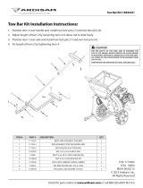
A minimum 20% of tractor and equipment
weight must be on the tractor front wheels when
attachments are in transport position. Without this
weight, front tractor wheels could raise up result-
ing in loss of steering. The weight may be attained
with front wheel weights, ballast in tires, front trac-
tor weights or front loader. Weigh the tractor and
equipment. Do not estimate.
Figure 1. Tractor Stability
NOTICE: The Compact Super Seeder is designed for
use on Category I, 3-point hitch tractors. See page 4
for specifications.
NOTICE: For Cat I fixed hitch usage, remove Quick
Hitch 5/8" bolt, nut and sleeve to prevent damage to
tractor’s 3-point top link.
1. Attach the tractor’s lower lift arms to the seeder
and secure with mounting pins and klik pins. See
Figure 2.
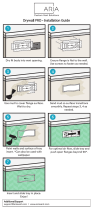
2. Attach the tractor’s top link to the mast plates of the
seeder. The seeder can be operated in a float or
fixed 3-point hitch position.
For beginning usage, the float position is
recommended. See Figure 2. To enable the seeder
to follow the contours of uneven ground, install the
tractor’s top link in the long slot in the top of the
mast plates. For proper float (up and down) the top
link pin should be centered in the slot
(recommended for beginners).
For controlled depth of tillage, use the fixed top link
position in the mast plates. See Figure 2.
For quick hitch use, install the available quick hitch
bushings. The seeder will not float with a quick
hitch installed. An optional Quick Hitch Bushing Kit,
P/N 1022043 is available.
3. Adjust the lower lift arm anti-sway device to
prevent excessive side-to-side movement of the
seeder.
4. Weigh tractor and seeder with seeder in transport
position. If necessary, add weight to obtain a
minimum of 20% of tractor and implement weight
on tractor front wheels. Weight may be attained
using front wheel weights, ballast on tires, front
roller weight, or front loader.
CAUTION

10 Operation
MAN1280 (4/05/2019)
Figure 2. Seeder Hitch Positions
HITCHING COMPACT SUPER SEEDER
WITH TOW KIT
■ Make sure shields and guards are properly
installed and in good condition. Replace if dam-
aged.
■ Never use an intermediate support as the pri-
mary attaching point for safety chain.
■ Never operate seeder equipped with tow kit
without safety chain properly attached to prime
mover. Replace safety chain if any links or fittings
are damaged or deformed.
1. Park seeder and prime mover on a level, hard
surface.
2. Adjust clevis hitch bracket on tow kit tongue so it is
level when attached to the prime mover.
3. Adjust the parking jack to match tow kit tongue
height to the prime mover drawbar height.
4. Pin the tongue to the prime mover drawbar.
NOTICE: When attaching seeder to tractor drawbar,
make sure the correct drawbar pin is used. A Category
1 drawbar pin is Ø1". Failure to use the correct pin size
will result in premature wear of hitch and drawbar hole.
If the hitch on the seeder doesn’t match your tractor
drawbar, contact your dealer to order the correct size
hitch for your tractor. If seeder will be attached to trac-
tor for a long period of time, secure hitch to drawbar
using a bolt, locknut, and washers assembled tightly.
This will reduce wear on drawbar and hitch.
5. Attach the safety chain to the prime mover with the
maximum distance between hitch pin and
intermediate support/primary attaching point. See
Figure 3. Route safety chain through hose holder
when not in use.
Figure 3. Safety Tow Chain Installation
NOTICE: Attach safety chain to prime mover with the
minimum possible slack in the chain. Failure to reduce
the slack could cause failure of hoses/wires and dam-
age primary components of the implement and/or
attached accessories.
6. Lower the parking jack until the tongue weight is
fully supported by the drawbar and the jack foot is
off the ground. Unpin the jack from the tongue.
7. Pin the jack to the operation location on top of the
"Y" section on tongue. See Figure 4. This location
prevents accidental contact with the rear tractor
tires, which could result in damage to the jack.
DP15
(Rev. 8/20/2019)

Operation 11
MAN1280 (4/05/2019)
Figure 4. Jack Positions
Attaching Electronic Harness
1. Attach wire harness from seeder to prime mover.
2. Route wire through the guide on the tow kit tongue
and be sure the wire can slide freely in the guide.
Do not allow wire slack to drag on the ground or
become caught on prime mover protrusions.
Attaching Hydraulic Hoses
1. Attach hydraulic hoses from the seeder to the
prime mover.
2. Route the hoses through the hose guide on the tow
kit tongue and be sure the hoses can slide freely in
the guide. Do not allow hose slack to drag on the
ground or become caught on prime mover
protrusions.
3. From the operator position, start the prime mover,
then raise and lower the seeder several times. This
will purge the hydraulic cylinder and hoses of
trapped air.
Interference Check
1. Be sure that the tractor 3-point arms do not
interfere with wire harness / hydraulic hoses or tow
kit components.
2. Check for straight ahead operation and full turning
angles. If there is any interference, remove the 3-
point arms.
IMPORTANT: Contact between 3-point arms and
seeder/tow kit can cause damage, especially when
turning.
COMPACT SUPER SEEDER ATTITUDE
ADJUSTMENT
The Compact Super Seeder can be used as both a till-
age tool and a seeding tool. When used strictly as a till-
age tool, a nose-down attitude will provide the most
aggressive tillage. When used for tillage and seeding at
the same time, a level attitude is preferable. If the Com-
pact Super Seeder is being used to seed already-tilled
soil, a slight nose-up attitude may be preferable for
minimum soil disturbance. With the seeder connected
to the tractor, attitude adjustments can be made by fol-
lowing these instructions:
Nose - Down Attitude Adjustment
3-Point Mounted
1. Lower seeder to the ground.
2. Pin the tractor top link into the fixed top link hole.
3. Shorten the tractor top link length until the drive
roller has been lifted off the ground a distance
equivalent to the desired tillage depth. Fix the top
link length by tightening the jam nut on the top link.
4. Resume operation and check performance.
Repeat as necessary.
Drawbar Mounted
1. Lower seeder to the ground.
2. With jack stand in the storage location and seeder
engaging the ground, unpin the adjustment
channel from tongue. Pinning farther from seeder
will provide more aggressive tillage.
3. Use jack stand to align adjustment channel with
appropriate hole on tongue. Pin in desired location.
4. Resume operation and check performance.
Repeat as necessary.
Nose - Up Attitude Adjustment
3-Point Mounted
1. Lower seeder to the ground.
DP15
(Rev. 8/20/2019)

12 Operation
MAN1280 (4/05/2019)
2. Pin the tractor top link into the fixed top link hole.
3. Lengthen the tractor top link length until the front
tool as been lifted off the ground a sufficient
distance. Fix the top link length by tightening the
jam nut on the top link.
4. Resume operation and check performance.
Repeat as necessary.
Drawbar Mounted
1. Lower seeder to the ground.
2. With jack stand in the storage location and seeder
engaging the ground, unpin adjustment channel
from tongue. Pinning closer to seeder will provide
less ground engagement.
3. Use jack stand to align adjustment channel with
appropriate hole on tongue. Pin in desired location.
4. Resume operation and check performance.
Repeat as necessary.
NOTICE: Excessive forward or rear attitude adjustment
will lead to poor performance and may cause equip-
ment damage or premature bearing failure.
COMPACT SUPER SEEDER GROUND
TOOL OPERATION
The Compact Super Seeder is an excellent turf recon-
ditioning tool, primary seeder, food plot and conserva-
tion seeder. Its ground penetration promotes a healthy
root system by allowing water, air, and sunlight to enter
the roots.
Front Rollers
When the front rollers are straight (Figure 5) and the
seeder is pulled forward, the front roller pins will pene-
trate the soil in a straight pushing action, and little dis-
turbance is caused to the turf.
Figure 5. Front Roller in Straight Position - Top View
(48" Seeder Shown)
The front rollers can be angled to promote a more
aggressive tearing action of the turf. The greater the
angle, the more tearing action is applied by the front
roller pins. For severe turf conditions, the maximum
angle position may be desired (Figure 6).
Figure 6. Maximum Front Roller Position - Top View
(48" Seeder Shown)
Adjusting Front Roller Angle
1. Position tractor and Overseeder on a level surface.
2. Place wooden blocks (minimum 4" thickness) on
ground to align with each end of Overseeder drive
roller. Raise seeder slightly off the ground, and
position the Overseeder over wooden blocks by
moving tractor. Do not allow wooden block to
contact the front roller. See Figure 7.
Figure 7. Overseeder above Wooden Blocks
3. Lower Overseeder to resting position on wooden
blocks for support during front roller adjustment.
(Follow tractor safe parking procedure in tractor
operator’s manual.)
4. Remove bent pins and hair pin clips from seeder
front tool adjustment. See Figure 9.

Operation 13
MAN1280 (4/05/2019)
Figure 8
5. Adjust RH and LH front gang assemblies
independently. Move tubes forward (see Figure 8)
for spiked front rollers. Keep RH and LH
adjustment angles the same for proper operation.
6. Reinstall bent pins to hold adjusted position.
7. Lift Overseeder and pull forward to clear wooden
blocks. Lower Overseeder to rest position on the
ground/level surface and install hair pin clips (see
Figure 8).
8. Reverse this procedure to move front rollers back
to straight position.
Front Disc
The front disc tool can be used to prepare a seedbed
without the need for a separate disc or tillage tool used
ahead of time. When the discs are straight, the seeder
has little soil disturbance. When the discs are angled
fully backward, there is maximum soil disturbance and
the seedbed can be prepared usually in one or two
passes. The disc has three angled positions to provide
an array of soil penetration depths and seedbed prepa-
ration.
Figure 9. Disc in Straight Position (60" Seeder Shown)
Figure 10. Disc in Angled Position (60" Seeder
Shown)
Adjusting Front Disc Angle
1. Position tractor and Overseeder on a level surface.
2. Place wooden blocks (minimum 4" thickness) on
ground to align with each end of Overseeder drive
roller. Raise seeder slightly off the ground and
position the Overseeder over wooden blocks by
moving tractor. Do not allow wooden block to
contact the front disc. (see Figure 7).
3. Lower Overseeder to resting position on wooden
blocks for support during front disc adjustment.
(Follow tractor safe parking procedure in tractor
operator’s manual).
4. Remove bent pins and hair pin clips from seeder
front tool adjustment (see Figure 11).
Figure 11
5. Adjust RH and LH front gang assemblies
independently. Move tubes rearward (see Figure
11) for concave disc blades. Keep RH and LH
adjustment angles the same for proper operation.
DP15
DP15

14 Operation
MAN1280 (4/05/2019)
6. Reinstall bent pins to hold adjusted position.
7. Lift Overseeder and pull forward to clear wooden
blocks. Lower Overseeder to rest position on the
ground/level surface, and install hair pin clips (see
Figure 11).
8. Reverse this procedure to move front disc back
into straight position.
IMPORTANT
■ Do not operate seeder in reverse. Operating
seeder in reverse may result in damage to seed
boxes and chain drive system.
Rear Roller
The rear roller firms and presses soil kicked up by the
front tillage tool. This creates a uniform seedbed with
the loose soil necessary for ensuring proper seed ger-
mination.
When the situation permits, make a second pass 90
degrees to the first for the roller pins to effectively pen-
etrate areas of uneven soil conditions.
In extremely compacted soil conditions, add extra
weight to the seeder to help the roller pins penetrate
the turf and soil sufficiently.
Chain Drive Disconnect
The Compact Super Seeder seed boxes can be
engaged or disengaged so that any one seed box or all
seed boxes can be operative or inoperative. See Fig-
ure 12 and Figure 25 for disconnect locations. It is not
recommended to run the plastic seed cup assemblies
without seed being metered.
It may be necessary to make several passes with the
ground engaging tools before planting seed. Disengag-
ing the seed box chain drive will allow the soil bed to be
prepared without planting seed or running the plastic
seed cup assemblies in a dry state.
Figure 12. Main Chain Drive Disconnect
Operation
The power for operating the seeder comes from con-
tact between the seeder rear roller and the turf.
■ Know how to stop the tractor and seeder
quickly in an emergency.
NOTICE: Survey the area to be worked and remove
any obstructions that may affect the performance of the
equipment.
SEEDING OPERATION
The Compact Super Seeder is capable of planting a
wide variety of seeds over a wide range of seeding
rates. The Compact Super Seeder is available with up
to two different seed boxes. To determine which seed
box is best for seeding, consider the planting depth and
size and shape of the seed.
The Cool Season seed box has a fluted roller seed cup
with an adjustable concave. The seed cup is capable of
planting large seeds including soybeans, grass seeds,
as well as small legume seeds. The seed cup metering
is adjustable with a common shaft and lever. As the
seed shaft is moved axially more or less of the fluted
seed roller is exposed changing the seed metering.
See Figure 17. Additional rates can be achieved by
changing the drive sprocket. The concave will need to
be opened as the size of the seed increases. Opening
the concave even further will also increase the seed
rate. Seed from the Cool Season seed box is dropped
on the divider and front seed tray. The roller then
pushes the seed and soil down creating a firm seed
bed with optimal seed to soil contact.
Seed stop plates, part number 1038658 shown in Fig-
ure 13, are available as accessories to increase row
width/reduce seeding rate. Place the seed stop plate
over the seed cup hole as shown. The shape of the
plate creates a tight fit.
Figure 13. Seed Stop Plates
Disengaged
Engaged
CAUTION

Operation 15
MAN1280 (4/05/2019)
The Legume seed box has a small seed cup and
adjustable fluted roller. The lever and shaft are similarly
adjustable to the Cool Season seed box. See Figure
20. The Legume seed box is ideal for planting alfalfa,
clover, forbes, rape and other small seeds. The seed
meter tubes attached to the Legume box can divert
seed to the primary transition tray for a deeper planting
depth or in front of the optional cultipacker for shallower
depths. See Figure 15.
Figure 14. Seed Boxes
IMPORTANT
■ Do not operate seeder in reverse. Operating
seeder in reverse may result in damage to seed
boxes and chain drive system.
Seed Box / Types of Seeds
SAMPLE SEED RATE CHARTS
NOTICE: For chain drives other than the standard drive, refer to the conversion charts for the multiplier to convert the
application rate to the correct value.
Cool Season Seed Rate Chart - Fast Chain Drive
COOL
SEASON
Annual Rye Grass, Barley, Kentucky Blue
Grass Blends, Fescue, Oats, Orchard Grass,
Perennial Rye Grass, Snow Peas, Sorghum,
Soybeans, Sunflower, Sudan, Wheat
LEGUME Alfalfa, Bahai, Bermuda, Birdsfoot Tree Foil,
Brassica, Buckwheat, Carpet Grass, Centi-
pede Grass, Chicory, Clover, Fescue, Forb,
Kentucky Blue Grass, Radishes, Rape,
Sudan, Switch Grass, Timothy, Turnip
(Rev. 8/20/2019)

16 Operation
MAN1280 (4/05/2019)
Cool Season Seed Rate Chart - Slow Drive
Legume Seed Rate Chart - Fast Chain Drive

Operation 17
MAN1280 (4/05/2019)
Legume Seed Rate Chart - Slow Chain Drive
NOTICE: These charts should only be used as guides. For more accurate rates, refer to the calibration section on
pages 22 and 23.
Figure 15. Transition Trays

18 Operation
MAN1280 (4/05/2019)
Filling the Seed Box
1. Calibrate seeder and set seed cup rate adjustment
and concaves to the correct position. Start with the
seed cup at a fully closed position and open the
seed cup to the desired fluted roller opening.
NOTICE: The seed cup can be opened further with
seed, but closing the seed cup or concave when
full of seed could result in seed cup damage. If the
seed cup must be restricted with seed in the seed
box, place a piece of cardboard over the seed cup
opening and remove seed in the seed cup by
opening the concave or rotating the seed shaft and
then closing the seed cup.
2. Open the seed box cover and rotate the brace to
hold the cover up while filling the seed box. Place
brace point in the covers spill guard notch. See
Figure 16.
3. Place seed in the seed box.
4. Lift brace and rotate to storage position. Close
seed cover and engage cover latch.
Figure 16. Seed Box Cover and Brace
Seed Rate Adjustment
Tractor speed and seed flow settings are critical for
proper seed population. Use the calibration tray to
adjust the seed cups for the desired seeding rate. Trac-
tor speed (normally 2-5 mph) should be established so
that uniform seed incorporation occurs with the action
of the rollers.
The slow chain drive, Figure 24 and Figure 25, comes
with the disc gang accessory. The fast chain drive, Fig-
ure 23 and Figure 26, comes with the spiked roller
accessory. If the other chain drive is desired for use
with the front tool, they can be purchased separately.
Seed Rate
Adjust the flow control lever (Figure 17 and Figure 20)
as needed for the seed being used and the population
desired. To adjust, loosen the plastic knob, move to
desired position and re-tighten the knob.
Figure 17. Cool Season Seed Rate Adjustment Lever
Figure 18. Pointer, Cool Season Box
Before seeding an area, adjust the top link so that it is
in the middle of the slot with the seeder on level
ground.
NOTICE: It is normal for the disc version to pitch for-
ward at maximum front tool angle.
Figure 19. Cool Season Seed Cup Concave
Adjustment
DP16
DP16
DP16
DP18
Concave Open -
Maximum Position
Concave
Closed
Concave

Operation 19
MAN1280 (4/05/2019)
Cool Season Seed Cup Concave Lever Adjustment
The Cool Season seed cup comes equipped with an
adjustable concave to handle a wide variety of seed
sizes. For small seeds, including grass seeds, the con-
cave should be at the highest position. This position
will prevent the loss of seed flowing through the seed
cup. For larger seeds, including soybeans, the concave
should be moved to a lower position. For minimum
seed rates, the concave should only be opened to the
size of the seed. This will prevent cracking of large
seeds by the seed cup. Opening further will increase
seed rates. See Figure 19.
Figure 20. Legume Seed Rate Adjustment Lever
Figure 21. Pointer, Legume Box
Legume Seed Cup
The Legume seed box is equipped with PVC tubes to
place the legume seed in the transition tray for the Pri-
mary seed box, ahead of the middle roller. The PVC
tubes can be repositioned in the Legume transition tray
for seed to be dropped ahead of the cultipacker.
Figure 22. Legume PVC Tubes
Operating Tips
IMPORTANT
■ Before closing down the cup (reducing rates),
the operator should make certain that the cups are
not full of seed. If cups are full of seed (especially
small, round, hard seed), it may be necessary to
cover the meter holes and run seeder a short dis-
tance to reduce level of seeds in meter. Failure to
do so could result in damage to seed cup.
■ Do not allow dirt to build up on the roller
sprockets. Clean sprockets and chain as needed.
Excessive buildup of material can cause damage to
the roller and idler shafts.
■ Always run the drive chain with some slack in
the chain. An extremely tight chain can damage the
roller shaft, the roller bearings, and the idler shaft
and bearing.
■ For optimum tillage or seeding ground pres-
sure with a tow kit accessory, do not lift wheels
completely off the ground. Lifting wheels com-
pletely off the ground can generate negative
tongue weight in some scenarios.
DP17
DP17
(Rev. 8/20/2019)

20 Operation
MAN1280 (4/05/2019)
Front Tool with Chain Drive Accessory
Figure 23. Fast Chain Drive
Figure 24. Slow Chain Drive
(Rev. 8/20/2019)
/