© 2008 • All rights reserved. 1
DLA2/4/6 Speaker Level Audio Router
Safety Information
NOTE: This equipment has been tested and found to comply with the limits for a Class B digital device, pursuant to part 15 of
the FCC Rules. These limits are designed to provide reasonable protection against harmful interference in a residential instal-
lation. This equipment generates, uses and can radiate radio frequency energy and, if not in-stalled and used in accordance
with the instructions, may cause harmful interference to radio communications. However, there is no guarantee that interfer-
ence will not occur in a particular installation.
If this equipment does cause harmful interference to radio or television reception, which can be determined by turning the
equipment off and on, the user is encouraged to try to correct the interference by one or more of the following measures:
Reorient or relocate the receiving antenna.•
Increase the separation between the equipment and receiver.•
Connect the equipment into an outlet on a circuit different from that to which the receiver is connected.•
Consult the dealer or an experienced radio/TV technician for help.•
CAUTION: Changes or modi cations not expressly approved by Elan Home Systems could void the user’s authority to operate
the equipment
DLA2/4/6 Power Source
The source of DLA2/4/6 power is the 12VDC wall transformer. A DC-IN jack connects the 12 VDC adapter with the DLA2/4/6
chassis to provide power for the unit. Protect the power supply cord from being walked on or pinched, particularly at plugs,
outlets and the point where they exit from the apparatus.
Severe personal injury and equipment damage can result by not following proper procedures. Use only the 12VDC adapter
designated for the DLA2/4/6.
Caring For the DLA2/4/6
Clean only with a dry soft cloth.
It is important to properly care for your DLA2/4/6 Speaker Selector. Follow these guidelines to ensure your device is preserved
and protected.
Do not expose the DLA2/4/6 to rain, liquids or moisture for an extended period of time.•
Do not expose the DLA2/4/6 to temperature extremes.•
Do not place any objects on top of the DLA2/4/6 to prevent chassis damage.•
Operating Temperatures & Environments
Operating Temperature: 32-104°F (0-40° C)•
Humidity: 0-90%•
Precautions
Always exercise care when operating the DLA2/4/6 Speaker Selector. •
Do not apply excessive amplification.•
ATON strongly recommends that you do not add more speakers than recommended.•
Do not install near any heat sources such as radiators, heat registers, stoves, or other apparatus (including •
amplifiers) that produce heat.
DO NOT use any 12 VDC adapter other than the one provided with the DLA2/4/6.•
In the unlikely event that smoke, abnormal noise, or strange odor is present, immediately power the DLA2/4/6 •
off. Please report the problem to your dealer immediately.
Never attempt to disassemble the DLA2/4/6. You will lose any product warranty on the unit.•
Ampli er Input 125 Watts per Channel Max
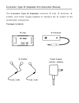
Package Contents
DLA2/4/6 Speaker Selector
12 VDC Power Adapter
Slim-Line IR Remote Control
User/Installation Manual
Quick
Install Guide