Page is loading ...

A2.indd 1 4/14/2009 2:03:40 PM

ELAN HOME SYSTEMS
© ELAN Home Systems 2009 • All rights reserved. Page I
A2 INSTALLATION MANUAL
Preface
Purpose of This Manual
This manual provides step-by-step installation instructions and connection examples, along with basic user
information for installation and ongoing use of the A2 Two Channel Amplifier. This manual is written for the
installer of this equipment.
Organization
The following information is contained in this manual:
Safety Information
Provides a comprehensive list of safety practices and procedures allow-
ing for the safe installation and operation of ELAN Home Systems’ A2 Two
Channel Amplifier.
A2 Introduction
Provides an introduction to the A2 Two Channel Amplifier, along with system
features to include Front and Rear panel controls, indicators and connec-
tions, along with a short description of each.
A2 System Design
Overview
Provides a system design application overview of the A2 Two Channel
Amplifier for use in audio applications.
A2 Connections
Provides a description of A2 Two Channel Amplifier connections including
connections made with ELAN Multi-Room Systems and direct connections
to the A2 Two Channel Amplifier from other components.
Troubleshooting
Provides troubleshooting tables to help fix common discrepancies that may
be associated with the A2 Two Channel Amplifier.
Specifications
Appendix A provides equipment specifications for the A2 Two Channel
Amplifier.
Rack Mounting
Appendix B provides specifications for Rack Mounting of the A2 Two
Channel Amplifier using the included rack mount brackets.
A2.indd 1 4/14/2009 2:03:40 PM

ELAN HOME SYSTEMS
Page II © ELAN Home Systems 2009 • All rights reserved.
A2 INSTALLATION MANUAL
RISK OF ELECTRIC SHOCK
DO NOT OPEN!
WARNING
CAUTION: TO REDUCE THE RISK OF ELECTRIC SHOCK, DO NOT
REMOVE COVER (OR BACK). NO USER SERVICEABLE PARTS INSIDE.
REFER SERVICING TO QUALIFIED SERVICE PERSONNEL.
WARNING: TO REDUCE THE RISK OF FIRE OR SHOCK,
DO NOT EXPOSE THIS APPLIANCE TO RAIN OR MOISTURE.
The lightning flash with arrowhead symbol within an equilateral triangle is intended to
alert the user to the presence of uninsulated "dangerous voltage" within the product's
enclosure that may be of sufficient magnitude to constitute a risk of electric shock to persons.
The exclamation point within an equilateral triangle is intended to alert the user to the presence
of important operating and maintenance (servicing) instruction in the literature accompanying
the appliance.
CAUTION
CAUTION: RISK OF EXPLOSION IF BATTERY IS REPLACED BY AN
INCORRECT TYPE. DISPOSE OF USED BATTERIES ACCORDING TO
THE INSTRUCTIONS.
Read Information—All the safety and operating information should be read before the appliance is operated.
Follow Information—All operating and use information should be followed.
Retain Information—The safety and operating information should be retained for future reference.
Heed Warnings—All warnings on the appliance and in the operating instructions should be heeded.
Wall Mounting—Mounting of this appliance should be done only by an authorized installer.
Ventilation—The appliances should be situated so that their location or position does not interfere with their proper ventilation. These appli-
ances should never be placed near or over a radiator or heat register. These appliances should not be placed in a built-in installation such as a
bookcase or cabinet that may impede the flow of air through the ventilation openings.
Non-Use Periods—Appliances that are left unattended and unused for long periods of time should be de-energized.
Power Sources—The appliances should be connected to a power supply only of the type described in the operating instructions or as
marked on each appliance. If you are not sure of the type of power supply to your home, consult your authorized ELAN dealer or local power
company.
Grounding or Polarization—Do not defeat the safety purpose of the polarized or grounding-type plug. A polarized plug has two
blades with one blade wider than the other blade. A grounding type plug has two blades and a third grounding prong. The polarized wide blade
and the third prong are provided for your safety. If the provided plug does not fit your outlet, consult an electrician for replacement of the obsolete
outlet.
Water and Moisture—To reduce the risk of electric shock or fire, these appliances should not be used near water ––for example, near a
bathtub, washbowl, kitchen sink, laundry tub, in a wet basement, or near a swimming pool.
Power Cord Protection—Protect the power cord from being walked on or pinched particularly at plugs, convenience receptacles and
the point where they exit from the apparatus.
Telephones—Avoid using a telephone (other than a cordless type) during an electrical storm. There may be a remote risk of electrical shock
from lightning. Do not use a telephone to report a gas leak if the leak is in the vicinity of the ELAN electronic equipment because of risk of fire or
explosion.
IMPORTANT SAFETY INFORMATION
A2.indd 2 4/14/2009 2:03:40 PM

ELAN HOME SYSTEMS
© ELAN Home Systems 2009 • All rights reserved. Page V
A2 INSTALLATION MANUAL
Table of Contents
Purpose of This Manual ....................................................................................................................... I
Organization ........................................................................................................................................... I
Safety Information ............................................................................................................................... II
Chapter 1:
Introduction
Introduction ........................................................................................................................................... 1
A2 Features ........................................................................................................................................... 1
A2 Functions & Indicators .................................................................................................................. 2
Front Panel .......................................................................................................................................... 2
Rear Panel ........................................................................................................................................... 3
Chapter 2:
A2 System Design Overview
System Design ...................................................................................................................................... 4
Pre-Wire .............................................................................................................................................. 4
Applications .......................................................................................................................................... 5
Applications ........................................................................................................................................ 5
Stereo Zones ...................................................................................................................................... 5
S66A/ S86A Application ....................................................................................................................... 11
S128P Application ............................................................................................................................. 13
Chapter 3:
A2 Connections
Connections ........................................................................................................................................ 15
Line Inputs ........................................................................................................................................ 15
Line Outputs ...................................................................................................................................... 16
Speaker Connections .................................................................................................................... 17
Triggers .............................................................................................................................................. 18
System Trigger In ............................................................................................................................... 18
System Trigger Out ............................................................................................................................ 18
Chapter 4:
Operations and Settings ............................................................................................... 19
Chapter 5: Troubleshooting .............................................................................................................. 20
Appendix A: Specifications ............................................................................................................... 22
Appendix B: Rack Mounting ............................................................................................................ 23
Warranty ................................................................................................................................ Back Page
A2.indd 5 4/14/2009 2:03:40 PM

ELAN HOME SYSTEMS
Page VI © ELAN Home Systems 2009 • All rights reserved.
A2 INSTALLATION MANUAL
Items in package:
A2 Power Amplifier•
Rack Mount Brackets•
Power Cord•
Installation Manual•
A2.indd 6 4/14/2009 2:03:40 PM

ELAN HOME SYSTEMS
© ELAN Home Systems 2009 • All rights reserved. Page 1
A2 INSTALLATION MANUAL
Chapter 1: Introduction
Boasting 150 Watts per channel at 2 ohms, the ELAN A2 Power Amplifier is designed and engineered to be the
definitive cornerstone component for any high-power application. The A2’s discrete output circuitry easily powers up
to three pairs of 8 ohm speakers simultaneously, eliminating the need for speaker selector boxes or load protection
devices. Buffered loop outputs provide easy connection of additional amplifiers. Using proven analog technology,
the A2 adds advanced features like Trigger Inputs/Outputs to make it the premier two channel amplifier in its price
range.
A2 Features
2 x 60 Watts per Channel @ 8 Ohms
2 x 100 Watts per Channel @ 4 Ohms
2 x 150 Watts per Channel @ 2 Ohms
Buffered Line Outputs
• allow the signal to be sent to other A2 amplfiers, A/V receivers, etc.
System Trigger In/Out
• SYSTEM TRIGGER IN allows all channels of the amplifier to UNMUTE
when a signal is received.
• SYSTEM TRIGGER OUT sends a +12VDC pulse whenever any of the
channels of the amplifier are UNMUTED.
Individual Channel Level Adjustment
• Fine-tune each channel’s level using precision potentiometers.
5-Way Speaker Binding Post
• The A2 is equipped with gold plated, 5-way speaker binding posts.
This allows for five methods of speaker wire termination: bare wire,
spade lug, pin, single banana and dual banana plug.
Safety Concerns
Use only grounded outlets when powering this product. Making any modification to the power cord could cause
unsafe operation and will void the manufacturer’s warranty.
AC Power Considerations
The A2 requires 3.7 Amps of AC current. When designing any whole house system using multichannel amplifiers,
make sure to provide adequate provisions for all electronic equipment to be installed. This may require additional
outlets and/or circuit breakers tobe installed. Consult a licensed electrician in this case.
ALL CONNECTIONS SHOULD BE MADE
WITH THE AMPLIFIER TURNED OFF
AND UNPLUGGED FROM POWER.
DAMAGE CAN OCCUR TO EQUIPMENT
IF IMPROPER CONNECTIONS ARE MADE!
THIS AMPLIFIER IS NOT BRIDGEABLE!
DO NOT TR TO BRIDGE
OR COMBINE OUTPUTS!
DAMAGE TO THE AMP WILL OCCUR.
A2.indd 1 4/14/2009 2:03:40 PM

ELAN HOME SYSTEMS
Page 2 © ELAN Home Systems 2009 • All rights reserved.
A2 INSTALLATION MANUAL
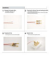
A2 Functions and Indicators
FRONT
1
2
3
Figure 1-1: A2 Front Panel
Table 1-1:Front Panel
Item Function
1
Channel Gain Potentiometers (2)
2
Pull-Out Access Door
3
POWER LED - Glows Blue When Power Switch is ON and Unit Plugged In
A2.indd 2 4/14/2009 2:03:40 PM

ELAN HOME SYSTEMS
© ELAN Home Systems 2009 • All rights reserved. Page 3
A2 INSTALLATION MANUAL
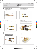
A2 Rear
BACK
1
2 3
4
5
}
6
Figure 1-2: A2 Rear Panel
Table 1-2: Rear Panel
Item Function
1
POWER SWITCH
2
POWER CORD
3
SPEAKER OUTPUTS
4
SYSTEM TRIGGER IN/OUT
5
LINE OUTPUTS
6
LINE INPUTS
A2.indd 3 4/14/2009 2:03:41 PM

ELAN HOME SYSTEMS
Page 4 © ELAN Home Systems 2009 • All rights reserved.
A2 INSTALLATION MANUAL
Chapter 2. System Design & Applications
System Design
The first step to a good design is to map the system. It is advisable to mark up a copy of the house floor plan with
speaker, keypad, touch panel, volume control, and equipment locations etc. Make sure that all locations are decided
upon before pre-wiring commences so that all necessary wiring and installation hardware is in place. This unit will
be interfacing with other components such as multi-room controllers, source components, communications control-
lers, serial controllers, and user interfaces, so it is essential that ALL system components are accounted for prior to
the pre-wire stage.
Secondly, make a detailed list of all components. Include source equipment, keypads, touch panels, volume con-
trols, amplifiers, and communications gear. Be sure to include necessary electrical boxes, structured wiring enclo-
sures, telephone lines, rough-in brackets, patch cords, power supplies, etc.
TM
S66A
A2 Amplifier
C2
A/V Sources
SPP
(side view)
Sensors
External IR
Receivers
SS1
Keypads
AUDIO SENSOR
SPK SPK SPK SPK
Olé
Touchpads
FrontRear
Triggered
Devices
Figure 2-1: System Design
Pre-Wire
Wiring Considerations
• Speaker Wires 28-16 AWG Speaker Wire
• Audio Cables RCA Patch Cables
• Triggers 2 Conductor Wire w/ 3.5mm mono connector
A2.indd 4 4/14/2009 2:03:41 PM

ELAN HOME SYSTEMS
© ELAN Home Systems 2009 • All rights reserved. Page 5
A2 INSTALLATION MANUAL
Applications
The A2 is specifically designed for multi-speaker applications. Three parallel amplifiers per channel provide high-cur-
rent drive for high-impact bass performance. The A2 also features three pair of gold-plated 5-way binding posts for
easy connection of multiple speaker pairs, a Remote Audio Mute Circuit that eliminates any “noise” that might come
through the speakers when the source components are not in use and 'installer-friendly' Channel Level Adjustments
which are easily accessible via the front panel.
4 Ohm Speakers
Since the A2 Power Amplifier is stable down to a 2 ohm load, it can handle multiple speaker pairs wired in
parallel. The following diagrams show the maximum number of speaker pairs than can be connected to the A2.
• Audio Output to Line Inputs 1 & 2
Each Zone’s Speakers Volume Ramps Up & Down Simultaneously
A2
RL
Line Level
Analog Audio
Output
4 OHM
Speakers
4 OHM
Speakers
Maximum # of 4 Ohm
speaker pairs without
Volume Controls
2
Figure 2-2: 4 Ohm Speaker Example
A2.indd 5 4/14/2009 2:03:41 PM

ELAN HOME SYSTEMS
Page 6 © ELAN Home Systems 2009 • All rights reserved.
A2 INSTALLATION MANUAL
4 Ohm Speakers w/ Volume Controls
Since the A2 Power Amplifier is stable down to a 2 ohm load, it can handle multiple speaker pairs wired in
parallel. The following diagrams show the maximum number of speaker pairs than can be connected to the A2.
• Audio Output to Line Inputs 1 & 2
• Volume Controls on Each Speaker Output
Each Zone’s Speakers Volume Ramps Up & Down Independently
A2
RL
Line Level
Analog Audio
Output
4 OHM
Speakers
4 OHM
Speakers
Maximum # of 4 Ohm
speaker pairs without
Volume Controls
2
Impedance
Match
Set to 1X
Impedance
Match
Set to 1X
Figure 2-3: 4 Ohm Speakers w/ Volume Controls
Maximum # of 4 Ohm speaker using Impedance Match Volume Controls
Impedance Match 4 Ohm Speaker Pairs
1X 2
2X 3
4X 4
8X 8
A2.indd 6 4/14/2009 2:03:41 PM

ELAN HOME SYSTEMS
© ELAN Home Systems 2009 • All rights reserved. Page 7
A2 INSTALLATION MANUAL
6 Ohm Speakers
• Audio Output to Line Inputs 1 & 2
Each Zone’s Speakers Volume Ramps Up & Down Simultaneously
A2
RL
Line Level
Analog Audio
Output
6 Ohm
Speakers
6 Ohm
Speakers
Maximum # of 6 Ohm
speaker pairs without
Volume Controls
3
6 Ohm
Speakers
Figure 2-4: 6 Ohm Speaker Example
A2.indd 7 4/14/2009 2:03:41 PM

ELAN HOME SYSTEMS
Page 8 © ELAN Home Systems 2009 • All rights reserved.
A2 INSTALLATION MANUAL
6 Ohm Speakers w/ Volume Controls
• Audio Output to Line Inputs 1 & 2
• Volume Controls on Each Speaker Output
Each Zone’s Speakers Volume Ramps Up & Down Independently
A2
RL
Line Level
Analog Audio
Output
6 Ohm
Speakers
6 Ohm
Speakers
Maximum # of 6 Ohm
speaker pairs without
Volume Controls
3
6 Ohm
Speakers
Impedance
Match
Set to 1X
Impedance
Match
Set to 1X
Impedance
Match
Set to 1X
Figure 2-5: 6 Ohm Speakers w/ Volume Controls
Maximum # of 6 Ohm speaker using Impedance Match Volume Controls
Impedance Match 6 Ohm Speaker Pairs
1X 3
2X 4
4X 6
8X 12
A2.indd 8 4/14/2009 2:03:42 PM

ELAN HOME SYSTEMS
© ELAN Home Systems 2009 • All rights reserved. Page 9
A2 INSTALLATION MANUAL
8 Ohm Speakers
• Audio Output to Line Inputs 1 & 2
Each Zone’s Speakers Volume Ramps Up & Down Simultaneously
A2
RL
Line Level
Analog Audio
Output
8 Ohm
Speakers
8 Ohm
Speakers
Maximum # of 8 Ohm
speaker pairs without
Volume Controls
4
8 Ohm
Speakers
8 Ohm
Speakers
Figure 2-6: 8 Ohm Speaker Example
A2.indd 9 4/14/2009 2:03:44 PM

ELAN HOME SYSTEMS
Page 10 © ELAN Home Systems 2009 • All rights reserved.
A2 INSTALLATION MANUAL
8 Ohm Speakers w/ Volume Controls
• Audio Output to Line Inputs 1 & 2
• Volume Controls on Each Speaker Output
Each Zone’s Speakers Volume Ramps Up & Down Independently
A2
RL
Line Level
Analog Audio
Output
8 Ohm
Speakers
8 Ohm
Speakers
Maximum # of 8 Ohm
speaker pairs without
Volume Controls
4
8 Ohm
Speakers
8 Ohm
Speakers
Impedance
Match
Set to 1X
Impedance
Match
Set to 1X
Impedance
Match
Set to 1X
Impedance
Match
Set to 1X
Figure 2-7: 8 Ohm Speakers w/ Volume Controls
Maximum # of 8 Ohm speaker using Impedance Match Volume Controls
Impedance Match 8 Ohm Speaker Pairs
1X 4
2X 6
4X 8
8X 16
A2.indd 10 4/14/2009 2:03:45 PM

ELAN HOME SYSTEMS
© ELAN Home Systems 2009 • All rights reserved. Page 11
A2 INSTALLATION MANUAL
Multi-Room
Stereo Sub-Zones
ELAN’s S66A/S86A Integrated Multi-Room Controllers have built-in amplification for six stereo zones as well as six
sets of preamp outputs for the addition of sub-zones. The A2 is ideally suited to amplify outdoor subzones using
rotary or electronic volume controls if separate volume up/down functionality is desired in the sub-zones as shown
in the S66A example below.
S66A Stereo Sub-Zones
• Preamp Output 1 & 2 to Line Inputs 1 & 2
• Preamp DIP Switches in VARIABLE Position
Each Zone and Sub-Zone Speakers Volume Ramps Together
A2
S66A
Maximum # of 8 Ohm
speaker pairs without
Volume Controls
4
Outdoor
Speakers
Outdoor
Speakers
Outdoor
Speakers
Outdoor
Speakers
Variable
Figure 2-8: S66A Sub-Zones
A2.indd 11 4/14/2009 2:03:46 PM

ELAN HOME SYSTEMS
Page 12 © ELAN Home Systems 2009 • All rights reserved.
A2 INSTALLATION MANUAL
S66A Stereo Sub-Zones
• Preamp Output 1 & 2 to Line Inputs 1 & 2
• Preamp DIP Switches in FIXED Position
• Volume Controls on Each Speaker Output
Each Zone and Sub-Zone Has Independent Volume Control
A2
S66A
Maximum # of 8 Ohm
speaker pairs without
Volume Controls
4
Outdoor
Speakers
Outdoor
Speakers
Outdoor
Speakers
Outdoor
Speakers
Fixed
Figure 2-9: S66A Sub-Zones
A2.indd 12 4/14/2009 2:03:48 PM

ELAN HOME SYSTEMS
© ELAN Home Systems 2009 • All rights reserved. Page 13
A2 INSTALLATION MANUAL
S128P Stereo Sub-Zones
ELAN’s S128P Integrated Multi-Room Controller has variable preamp outputs for eight stereo zones as well as eight
sets of fixed preamp outputs for the addition of sub-zones. The A2 has the ability to provide high power to large
area such as Great Rooms. Use rotary or electronic volume controls if separate volume up/down functionality is
desired in the sub-zones.
S128P Stereo Sub-Zones
• RCA Line Out cables in VARIABLE Preamp Outputs
Each Zone and Sub-Zone Speakers Volume Ramps Together
S128P
A2
Maximum # of 8 Ohm
speaker pairs without
Volume Controls
4
Great Room
Speakers
Great Room
Speakers
Great Room
Speakers
Great Room
Speakers
Figure 2-10: S128P Sub-Zones
A2.indd 13 4/14/2009 2:03:49 PM

ELAN HOME SYSTEMS
Page 14 © ELAN Home Systems 2009 • All rights reserved.
A2 INSTALLATION MANUAL
S128P Stereo Sub-Zones
• Fixed Preamp Output 1 & 2 to Line Inputs 1 & 2
• RCA Line Out cables in FIXED Outputs
• Volume Controls on Each Speaker Output
Each Zone and Sub-Zone Has Independent Volume Control
S128P
A2
Maximum # of 8 Ohm
speaker pairs without
Volume Controls
4
Great Room
Speakers
Great Room
Speakers
Great Room
Speakers
Great Room
Speakers
Figure 2-6: S128P Sub-Zones
A2.indd 14 4/14/2009 2:03:51 PM

ELAN HOME SYSTEMS
© ELAN Home Systems 2009 • All rights reserved. Page 15
A2 INSTALLATION MANUAL
Chapter 3: Connections
The A2 has several rear panel connections so it is important to label all cables and wires correctly. Label all input/
output cable and speaker wires with their destination or source. This will save time during installation and any future
upgrades to the system.
Use high quality line level RCA connector type cables for source connections to ensure the lowest possible noise
and best sound performance. For most applications use 16AWG 2 conductor speaker cable. For wiring runs longer
than 80 ft. it is recommended to use 14AWG 2 conductor speaker cable. The A2's high quality, gold plated 5-way
binding post will accomodate speaker cabling sizes up to 12AWG. Attaching banana plugs will enable the connec-
tion of larger cable sizes. A 3.5mm mono interconnect cable may be used for amplifier and systems triggering.
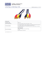
Line Level Audio Inputs
Connect the zones by inserting the RCA connectors into the dedicated direct input jack on each channel.
A2
From Audio
Output Source
RCA Patch
Cable
Figure 3-1: Line Inputs
A2.indd 15 4/14/2009 2:03:51 PM
/