Page is loading ...

A275
Two-Channel Power Ampli er
INSTALLATION MANUAL
P/N 9803392 REV:B

ATON
© ATON 2010 • All rights reserved. Page I
A275 INSTALLATION MANUAL
Preface
Purpose of This Manual
This manual provides step-by-step installation instructions and connection examples, along with basic user information for instal-
lation and ongoing use of the A275 Two-Channel Power Amplifier. This manual is written for the installer of this equipment.
Organization
The following information is contained in this manual:
Safety Information Provides a comprehensive list of safety practices and procedures allowing for the safe
installation and operation of ATON's A275 Two-Channel Power Amplifier.
A275 Introduction Provides an introduction to the A275 Two-Channel Power Amplifier, along with system
features to include Front and Rear panel controls, indicators and connections, along with
a short description of each.
A275 System Design Overview Provides a system design application overview of the A275 Two-Channel Power Amplifier
for use in audio applications.
A275 Connections Provides a description of A275 Two-Channel Power Amplifier connections including
connections made with ATON Multi-Room Systems and direct connections to the A275
Two-Channel Power Amplifier from other components.
Troubleshooting Provides troubleshooting tables to help fix common discrepancies that may
be associated with the A275 Two-Channel Power Amplifier.
Specifications Appendix A provides equipment specifications for the A275 Two-Channel Power Amplifier.
Rack Mounting Appendix B provides specifications for Rack Mounting of the A275 Two-Channel Power
Amplifier using the included rack mount brackets.

ATON
Page II © ATON 2010 • All rights reserved.
A275 INSTALLATION MANUAL
RISK OF ELECTRIC SHOCK
DO NOT OPEN!
WARNING
CAUTION: TO REDUCE THE RISK OF ELECTRIC SHOCK, DO NOT
REMOVE COVER (OR BACK). NO USER SERVICEABLE PARTS INSIDE.
REFER SERVICING TO QUALIFIED SERVICE PERSONNEL.
WARNING: TO REDUCE THE RISK OF FIRE OR SHOCK,
DO NOT EXPOSE THIS APPLIANCE TO RAIN OR MOISTURE.
The lightning flash with arrowhead symbol within an equilateral triangle is intended to
alert the user to the presence of uninsulated "dangerous voltage" within the product's
enclosure that may be of sufficient magnitude to constitute a risk of electric shock to persons.
The exclamation point within an equilateral triangle is intended to alert the user to the presence
of important operating and maintenance (servicing) instruction in the literature accompanying
the appliance.
CAUTION
CAUTION: RISK OF EXPLOSION IF BATTERY IS REPLACED BY AN
INCORRECT TYPE. DISPOSE OF USED BATTERIES ACCORDING TO
THE INSTRUCTIONS.
Read Information—All the safety and operating information should be read before the appliance is operated.
Follow Information—All operating and use information should be followed.
Retain Information—The safety and operating information should be retained for future reference.
Heed Warnings—All warnings on the appliance and in the operating instructions should be heeded.
Wall Mounting—Mounting of this appliance should be done only by an authorized installer.
Ventilation—The appliances should be situated so that their location or position does not interfere with their proper ventilation. These appliances should never be
placed near or over a radiator or heat register. These appliances should not be placed in a built-in installation such as a bookcase or cabinet that may impede the flow of
air through the ventilation openings.
Non-Use Periods—Appliances that are left unattended and unused for long periods of time should be de-energized.
Power Sources—The appliances should be connected to a power supply only of the type described in the operating instructions or as marked on each appliance.
If you are not sure of the type of power supply to your home, consult your authorized ATON dealer or local power company.
Grounding or Polarization—Do not defeat the safety purpose of the polarized or grounding-type plug. A polarized plug has two blades with one blade wider
than the other blade. A grounding type plug has two blades and a third grounding prong. The polarized wide blade and the third prong are provided for your safety. If
the provided plug does not fit your outlet, consult an electrician for replacement of the obsolete outlet.
Water and Moisture—To reduce the risk of electric shock or fire, these appliances should not be used near water ––for example, near a bathtub, washbowl,
kitchen sink, laundry tub, in a wet basement, or near a swimming pool.
Power Cord Protection—Protect the power cord from being walked on or pinched particularly at plugs, convenience receptacles and the point where they exit
from the apparatus.
Telephones—Avoid using a telephone (other than a cordless type) during an electrical storm. There may be a remote risk of electrical shock from lightning. Do not
use a telephone to report a gas leak if the leak is in the vicinity of the ATON electronic equipment because of risk of fire or explosion.
IMPORTANT SAFETY INFORMATION

ATON
© ATON 2010 • All rights reserved. Page III
A275 INSTALLATION MANUAL
Cleaning—Unplug the apparatus from the power outlet before cleaning. Use only a dry cloth to clean the apparatus.
Power Lines—An outdoor antenna should be located away from power lines. When installing an outside antenna system, extreme care should be taken to avoid
touching power lines or circuits, as contact with them may be fatal.
Outdoor Antenna Grounding—If an outside antenna or cable system
is connected to these audio products, be sure the antenna or cable system is grounded
so as to provide some protection against voltage surges and built-up static charg-
es. Section 810 of the U.S. National Electrical Code, and Section 54 of the
Canadian Electrical Code, provide information with respect to proper grounding of
the mast and supporting structure, grounding of the lead-in wire to an antenna
discharge unit, size of grounding conductors, location of antenna-discharge unit,
connection to grounding electrodes, and requirements for the grounding electrode.
See the grounding diagram (right).
Overloading—Do not overload wall outlets and extension cords, as this could
result in fire or electric shock.
Object and Liquid Entry—Never insert objects of any kind through the
openings of these appliances, as they may touch dangerous voltage points or
short-out parts that could result in a fire or electric shock. Care should be taken so that
objects do not fall and liquids are not spilled into the appliance through openings in the enclosure.
Servicing—Do not attempt to service these appliances yourself, as opening or removing covers may expose you to dangerous voltage or other hazards. Refer all
servicing to qualified service personnel.
Damage Requiring Service—These appliances should be serviced by qualified service personnel when:
• A power supply connection or a plug has been damaged or
• If liquid has been spilled into the appliance or objects have fallen into the appliance or
• The appliance has been exposed to water or moisture or
• The appliance does not appear to operate normally or exhibits a marked change in performance or
• The appliance has been dropped or the enclosure damaged.
Replacement Parts—When replacement parts are required, be sure the service technician has used replacement parts specified by the manufacturer or that
have the same characteristics as the original part. Unauthorized substitutions may result in fire, electric shock, or other hazards. The Master Control Unit battery should be
replaced only after turning the power off and only by an authorized installer.
Safety Check—Upon completion of any service or repairs to this audio product, ask the service technician to perform safety checks to determine that the audio
product is in proper operating condition.
Lightning Storms—Unplug this apparatus during lightning storms or when unused for long periods of time.
Attachments and Accessories—Use only attachments/accessories specified by the manufacturer.
Cart, Stand, Tripod, Bracket or Table—Use only with a cart, stand, tripod, bracket or table specified by the manufacturer, or sold with the apparatus.
When a cart is used, use caution when moving the cart/apparatus combination to avoid injury from tip over.
Disconnect Device—Where the mains plug or an appliance coupler is used as the disconnect device, the disconnect device shall remain operable.
®
US
C
ELECTRIC
SERVICE
EQUIPMEN T
GROUND
CLAMPS
POWERSER VICE GROUNDING
ELECTRODESYSTEM
(CECSECTION 10-700)
ANTENNA
LEAD-IN WIRE
GROUND CLAMPS
GROUNDING CONDUCTORS
(CECSECTION 54-200)
ANTENNA LEAD-IN WIRE
(CECSECTION 54-200)
NE C-NAT IONAL ELECTRICAL CODE
(NEC SECTION 810-20)
(NEC SECTION 810-21)
(NEC AR TICLE 250, PA RT H)
CE C-CANADIAN ELECTRICAL CODE
Grounding
Diagram
®
US
C
®
US
C

ATON
Page IV © ATON 2010 • All rights reserved.
A275 INSTALLATION MANUAL

ATON
© ATON 2010 • All rights reserved. Page V
A275 INSTALLATION MANUAL
Table of Contents
Purpose of This Manual ................................................................................................................................................................................................................................................................................................................................................................................................................................................................................................................................. I
Organization ............................................................................................................................................ I
Safety Information .................................................................................................................................. I
Chapter 1: Introduction
Introduction ........................................................................................................................................... 1
A275 Features ..................................................................................................................................................1
A275 Functions & Indicators
........................................................................................................................................................2
Front Panel .......................................................................................................................................................................................2
Rear Panel .................................................................................................................................................... 2
Chapter 2:
A275 System Design Overview
System Design
Wiring Considerations .................................................................................................................................... 3
Applications ..............................................................................................................................................................................3-5
Amp and Speaker Selector Applications ................................................................................................ 3-4
Volume Control Applications .................................................................................................................... 5
Multi-Room Applications ...................................................................................................................... 6-7
Chapter 3:
A275 Connections
Connections
Line Inputs ................................................................................................................................................... 8
Line Output ...................................................................................................................................................9
Speaker Connections .................................................................................................................................. 10
Triggers ...................................................................................................................................................... 11
Chapter 4:
Operations and Settings .............................................................................................................12
Chapter 5:
Troubleshooting .....................................................................................................................13-14
Appendix A: Specifications
............................................................................................................................ 15
Appendix B: Rack Mounting
......................................................................................................................16-17
Warranty
.........................................................................................................................................................20

ATON
Page VI © ATON 2010 • All rights reserved.
A275 INSTALLATION MANUAL
Items in package:
A275 Two-Channel Power Amplifier•
Rack Mount Brackets•
Installation Manual•
A275
Power Ampli er

ATON
© ATON 2010 • All rights reserved. Page 1
A275 INSTALLATION MANUAL
Chapter 1: Introduction
Thank you for purchasing the ATON A275 Two-Channel Power Amplifier. Soon you will be experiencing the quality and reliability we
place in all of our products. The backbone of any distributed audio system is the amplification. The true test of any amplifier is the abil-
ity to drive multiple speakers at low impedance for hours on end. In this arena, the A275 excels! Heat is the number cause for amplifier
failure, or temporary audio loss from thermal shutdown protection circuitry, a.k.a. overheating. Of course that typically happens when
you are entertaining a house full of guests! ATON designed the A275 with 2 long rows of external cooling fins to increase the heat dis-
sipation capability. Higher cooling capacity equals longer product life, cleaner audio signal, and of course, more satisfied customers!
A275 Features
• 2 x 45 Watts per Channel @ 8 Ohms
• 2 x 75 Watts per Channel @ 4 Ohms
Buffered Line Outputs
• Allow the signal to be sent to other A275 amplfiers, A/V receivers, etc.
System Trigger In/Out
• SYSTEM TRIGGER IN allows all channels of the amplifier to UNMUTE when a signal is received.
• SYSTEM TRIGGER OUT sends a +12VDC pulse whenever any of the channels of the amplifier are UNMUTED.
Individual Channel Level Adjustment
• Fine-tune each channel’s level using precision potentiometers.
5-Way Speaker Binding Post
• The A275 is equipped with gold plated, 5-way speaker binding posts. This allows for five methods of speaker wire termination:
bare wire, Spade lug, pin, single banana and dual banana plug.
Safety Concerns
Use only grounded outlets when powering this product. Making any modification to the power cord could cause unsafe operation and
will void the manufacturer’s warranty.
AC Power Considerations
The A275 requires 3.7 Amps of AC current. When designing any whole house system using multichannel amplifiers, make sure to
provide adequate provisions for all electronic equipment to be installed. This may require additional outlets and/or circuit breakers to
be installed. Consult a licensed electrician in this case.

ATON
Page 2 © ATON 2010 • All rights reserved.
A275 INSTALLATION MANUAL
A275 Front Panel Functions and Indicators
FRONT
1
2
Item Function
1
Channel Gain Potentiometers (2)
2
Pull-Out Access Door
3
POWER LED - Glows Blue When Power Switch is ON and Unit Plugged In
ITEM FUNCTION
Channel Gain Potentiometers (2)
POWER LED Glows blue when power switch is ON and unit is plugged in.
1
2
Figure 1-1: A275 Front Panel
Table 1-1:Front Panel
ITEM FUNCTION
POWER SWITCH
POWER CORD
SPEAKER OUTPUTS
SYSTEM TRIGGER IN/OUT
LINE OUTPUTS
LINE INPUTS
1
2
3
4
5
6
BACK
1
2
3
4
5
}
6
A275 Back Panel
2
Figure 1-2: A275 Back Panel
Table 1-2: Back Panel

ATON
© ATON 2010 • All rights reserved. Page 3
A275 INSTALLATION MANUAL
Chapter 2. System Design & Applications
System Design
The A275 is designed to drive multiple pairs of indoor or outdoor speakers from virtually any audio source. A typical installation con-
sists of a home theater receiver zone 2 or zone 3 line level output feeding the A275. The A275 amplified outputs can drive speakers,
volume controls, or ATON DLA speaker routers depending upon the application. The advantage of using a DLA along with the A275 is
the ability to drive multiple pairs of speakers while enjoying the benefits of the DLA Router: automatic impedance protection, dynamic
volume level adjustment, discrete IR remote control, and RF remote control. The A275 is designed to drive one or more DLA’s including
the DLA2, DLA4, or DLA6. If you need additional DLA configuration and setup assistance, please refer to the DLA installation manual.
HOME THEATER RECEIVER
A275
RL
Line Level
Analog Audio
Output
DLA4 SPEAKER SELECTOR
AMPLIFIER
INPUTS
SPEAKER
OUTPUTS
SPK
SPK
SPK
SPK
SPK
SPK
SPK
SPK
HOME THEATER RECEIVER
A275
RL
Line Level
Analog Audio
Output
DLA4 SPEAKER SELECTOR 1
AMPLIFIER
INPUTS
SPEAKER
OUTPUTS
SPK
SPK
SPK
SPK
SPK
SPK
SPK
SPK
DLA4 SPEAKER SELECTOR 2
AMPLIFIER
INPUTS
SPEAKER
OUTPUTS
SPK
SPK
SPK
SPK
SPK
SPK
SPK
SPK
8Ω 8Ω
4Ω 4Ω
8Ω 8Ω
4Ω 4Ω
8Ω 8Ω
4Ω 4Ω
8Ω 8Ω
4Ω 4Ω
8Ω 8Ω
4Ω 4Ω
Wiring Considerations
Speaker Wires Audio Cables Triggers
14-16 AWG Speaker Wire RCA Patch Cables 2 Conductor Wires with 3.5mm mono connector
A275 Speaker Outputs
DLA Speaker Inputs
RED
BLACK
WHITE
GREEN
W G B R
IMPORTANT!
In this application, the DLA's
"AMP" switch should be in the
down or "4" Ohm position. Set
the "SPKR" switch to the "4" or
"8" Ohm position depending on
the impedance of the speakers
being used.
SETTING UP THE A275 WITH A DLA SPEAKER SELECTOR
Figure 2-1: A275 and DLA SPEAKER SELECTOR
(DLA2, DLA4, or DLA6 can be used)

ATON
Page 4 © ATON 2010 • All rights reserved.
A275 INSTALLATION MANUAL
Wiring Considerations
Speaker Wires Audio Cables Triggers
14-16 AWG Speaker Wire RCA Patch Cables 2 Conductor Wires with 3.5mm mono connector
A275 Speaker Outputs
DLA Speaker Inputs
RED
BLACK
WHITE
GREEN
W G B R
Figure 2-2: A275 and MULTIPLE DLA SPEAKER SELECTORS
HOME THEATER RECEIVER
A275
RL
Line Level
Analog Audio
Output
DLA4 SPEAKER SELECTOR
AMPLIFIER
INPUTS
SPEAKER
OUTPUTS
SPK
SPK
SPK
SPK
SPK
SPK
SPK
SPK
HOME THEATER RECEIVER
A275
RL
Line Level
Analog Audio
Output
DLA4 SPEAKER SELECTOR 1
AMPLIFIER
INPUTS
SPEAKER
OUTPUTS
SPK
SPK
SPK
SPK
SPK
SPK
SPK
SPK
DLA4 SPEAKER SELECTOR 2
AMPLIFIER
INPUTS
SPEAKER
OUTPUTS
SPK
SPK
SPK
SPK
SPK
SPK
SPK
SPK
8Ω 8Ω
4Ω 4Ω
8Ω 8Ω
4Ω 4Ω
8Ω 8Ω
4Ω 4Ω
8Ω 8Ω
4Ω 4Ω
8Ω 8Ω
4Ω 4Ω
IMPORTANT!
In this application, the DLA's
"AMP" switch should be in the
UP or "8" Ohm position. Set the
"SPKR" switch to the "4" or "8"
Ohm position depending on the
impedance of the speakers being
used.
SETTING UP THE A275 WITH MULTIPLE DLA SPEAKER SELECTORS
(DLA2, DLA4, or DLA6 can be used)
(DLA2, DLA4, or DLA6 can be used)

ATON
© ATON 2010 • All rights reserved. Page 5
A275 INSTALLATION MANUAL
Applications
4/6/8 Ohm Speakers with Volume Controls
• Audio Output to Line Inputs 1 & 2
A275
RL
Line Level
Analog Audio
Output
Speakers
Speakers
ATON
VOLUME
CONTROL
AVC100R
or AVC100SL
Figure 2-3: 4/6/8 Ohm Speakers w/ Volume Controls
Using A275 with Impedance Match Volume Controls and Maximum Speaker Wattage
Volume Control
Impedance Match Setting
8 Ohm
Speaker Pairs
Max Wattage
Available Per
Speaker
6 Ohm
Speaker Pairs
Max Wattage
Available Per
Speaker
4 Ohm
Speaker Pairs
Max Wattage
Available Per Speaker
1X 4 18.0 3 24.0 2 36.0
2X 6 12.0 4 18.0 3 24.0
4X 8 6.0 6 9.0 4 12.0
8X 16 1.0 12 1.5
System Design Considerations
Adding multiple speakers to a power amplifier reduces the amount of power sent to each speaker as the total available wattage is
divided among the connected speakers. Beyond customer volume preferences, several factors affect overall amplifier output including
input signal gain, impedance, AC voltage, wire run length and gauge, insertion losses with volume controls, room size, etc. This chart
assumes simple math and does not represent actual dB, SPL calculations, etc. It is provided as a guideline only to demonstrate theory
& provide some basic design guidance. You can never overpower a system because you have dynamic headroom, or spare power as
needed. If you underpower / underamplify a system, the amplifier tends to be pushed past its safety zone which eventually leads to
clipping and system failure.
Indoor applications for background audio need only be a few watts, typically 1 to 10. For primary listening areas, you should plan on 5
to 20 watts or more depending upon application. Outdoor applications require a greater amount of power since there is little reflectivity
of sound and listening area is larger, so plan on 40 watts or more!
NOT RECOMMENDED

ATON
Page 6 © ATON 2010 • All rights reserved.
A275 INSTALLATION MANUAL
Multi-Room
Stereo Sub-Zones
ATON’s AH66T Integrated Multi-Room Controller has built-in amplification for six stereo zones as well as six sets of preamp outputs for
the addition of sub-zones. The A275 is ideally suited to amplify outdoor subzones using rotary or electronic volume controls if separate
volume up/down functionality is desired in the sub-zones as shown in the AH66T example below.
AH66T Stereo Sub-Zones
• Preamp Output 1 & 2 to Line Inputs 1 & 2
• Preamp DIP Switches in VARIABLE Position
Each Zone and Sub-Zone Speakers Volume Ramps Together
A275
AH66T MULTI-ROOM CONTROLLER
Variable (UP)
Speakers
Speakers
ATON
VOLUME
CONTROL
AVC100R
or AVC100SL
Figure 2-4: AH66T Sub-Zones
IMPORTANT NOTE
Please see chart on previous page for impedance match settings and volume controls

ATON
© ATON 2010 • All rights reserved. Page 7
A275 INSTALLATION MANUAL
AH66T Stereo Sub-Zones
• Preamp Output 1 & 2 to Line Inputs 1 & 2
• Preamp DIP Switches in FIXED Position
• Volume Controls on Each Speaker Output
Each Zone and Sub-Zone Has Independent Volume Control
A275
AH66T MULTI-ROOM CONTROLLER
Fixed (DOWN)
Outdoor
Speakers
Outdoor
Speakers
ATON
VOLUME
CONTROL
AVC100R
or AVC100SL
Figure 2-5: AH66T Sub-Zones
IMPORTANT NOTE
Please see chart on previous page for impedance match settings and volume controls

ATON
Page 8 © ATON 2010 • All rights reserved.
A275 INSTALLATION MANUAL
Chapter 3: Connections
The A275 has several rear panel connections so it is important to label all cables and wires correctly. Label all input/output cable and
speaker wires with their destination or source. This will save time during installation and any future upgrades to the system.
Use high quality line level RCA connector type cables for source connections to ensure the lowest possible noise and best sound per-
formance. For most applications use 16AWG 2 conductor speaker cable. For wiring runs longer than 80 ft. it is recommended to use
14AWG 2 conductor speaker cable. The A275's high quality, gold plated 5-way binding post will accommodate speaker cabling sizes up
to 12AWG. Attaching banana plugs will enable the connection of larger cable sizes. A 3.5mm mono interconnect cable may be used for
amplifier and systems triggering.
Line Level Audio Inputs
Connect the zones by inserting the RCA connectors into the dedicated direct input jack on each channel.
A275
From Audio
Output Source
RCA Patch
Cable
Figure 3-1: Line Inputs

ATON
© ATON 2010 • All rights reserved. Page 9
A275 INSTALLATION MANUAL
Line Ouputs
A stereo or monaural audio signal connected to the A275’s main LINE INPUT is routed to the A275’s RCA Line Outputs. This feature is
excellent for standalone distributed audio systems where one source (i.e. an A/V Receiver) is providing audio to the entire home, and also
for ATON multi-room applications where a zone’s audio signal needs to be routed to multiple amplifier channels. Examples of both these
applications are shown in the Chapter 2.
Line audio outputs enable connection of additional amplifiers to allow further system expansion. Use high quality RCA interconnect
cables to ensure low noise and great sound. The A275 Line Outputs are buffered, a maximum of four amplifiers may be 'daisy-chained'
to each Line Outputs.
A275 #1
From Audio
Output Source
RCA Patch
Cable
A275 #2
RCA Patch
Cable
To A275s
#3-4
Figure 3-2: Line Outputs

ATON
Page 10 © ATON 2010 • All rights reserved.
A275 INSTALLATION MANUAL
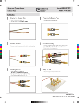
Speaker Binding Post
The A275 is equipped with gold plated, 5-way speaker binding posts. This allows five methods of speaker wire termination: bare wire,
spade lug, pin, single banana and dual banana plug. Label all speaker wires with their destination to ensure easy configuration. To attach
speaker wires use the following method:
1. Carefully split the speaker wire insulation at least two inches.
2. Strip 1/2 inch of the insulation from the speaker wire conductor exposing the bare wire.
3. Twist the wire strands of each conductor, if using banana plugs, attach wire to banana plug observing polarity.
4. If using banana plug; insert plug ends into binding post observing correct polarity. If using the bare wire method; loosen the
binding post caps and insert the bare wire through the hole in the post. Tighten the knob until the wire is securely clamped.
CAUTION! Speaker Wire connections must be made with the amplifier OFF!
Banana Plugs
Speaker Wire
A275 Amplifier
Binding Post
WARNING: Do not allow any strands
of the bare speaker wire to touch
the Amplifier Chassis or another
Connector.
Speaker Wire
1/2’
WHITE
GREEN
RED
BLACK
Figure 3-3: Speaker Binding Post

ATON
© ATON 2010 • All rights reserved. Page 11
A275 INSTALLATION MANUAL
Triggers
A REMOTE TRIGGER IN port allows all channels to turn on or mute simultaneously. The REMOTE TRIGGER INPUT can receive 5-24 Volts
AC or DC. The 12 Volt DC REMOTE TRIGGER OUT can be used to turn on other equipment, additional A275s or other amplifiers, or to
perform automated functions desired by the user. Use 3.5mm mono interconnect cables to make Trigger connections.
SYSTEM TRIGGER IN
To mute/un-mute all channels simultaneously, connect a system-wide 5-24 Volt DC triggering source to the SYSTEM TRIGGER IN port
using a 3.5mm mono interconnect cable. Examples of triggering sources include an ATON Multi-Zone Controller’s SYSTEM
TRIGGER OUT or REMOTE OUT, an A/V receiver’s switched outlet connected to a power supply, or a +12VDC TRIGGER OUT from another
ATON amplifier.
AH66T
A275
3.5mm mono interconnect cable
Figure 3-4: Remote Trigger In
SYSTEM TRIGGER OUT
Whenever the A275 is powered ON, the REMOTE TRIGGER OUT becomes active. This output sends a +12VDC 100mA signal to other
devices with a Trigger Input.
A275 #1
A275 #2
3.5mm mono interconnect cable
From AH66T
To A275’s
#3-4
Figure 3-5: Remote Trigger Out

ATON
Page 12 © ATON 2010 • All rights reserved.
A275 INSTALLATION MANUAL
Chapter 4: Operations & Settings
Setting Channel Levels
The A275 features independent Level Adjustment Potentiometers for each of its two channels. Use a small Phillips screwdriver to inde-
pendently adjust each channel of the amplifier for the specific speakers and environmental conditions of the area it is powering. Turning
the potentiometer clockwise increases the level, while turning it counter-clockwise decreases the level. Factory default is 85%.
Set the levels by first lowering them all the way down, then raise the volume of any keypads or volume controls to maximum. Slowly
increase the level of the channel being adjusted by turning the potentiometer clockwise until the channel begins to distort, then reduce the
level slightly (turn counter-clockwise) until distortion is no longer present. Follow this procedure for each channel.
1 2
LEVEL LEVEL
Factory
Default 50%
Figure 4-1: Level Adjustment Potentiometers
Factory Default
is 85%

ATON
© ATON 2010 • All rights reserved. Page 13
A275 INSTALLATION MANUAL
Chapter 5: Troubleshooting
Symptom Possible Cause Solution
No Audio From One or
More Channels
1. Loose/bad speaker cable connection
2. Break/short in speaker cable
3. Speaker is defective
4. RCA patch cable defective
5. Source not sending audio
1. Check cable ends at binding posts and
speaker terminals.
2. Check continuity of each speaker cable
using multimeter. If short or open is indi-
cated, check wiring for proper connections.
3. Swap with known good speaker.
4. Swap with known good patch cable.
5. Verify source is powered up and playing.
Check any tape monitor settings on A/V
Receiver.
No Audio From One Channel Amplifier is overheating due to
inadequate ventalation or prolonged opera-
tion at clipping levels.
1. (a) Turn the amplifier off and allow the
internal circuits to cool.
(b) Ensure that the amplifier has proper
ventilation. Add cooling fan if necessary.
(c) Lower the gain level controls for that
channel pair.
No Audio From One Channel Unit may require service. Contact ATON Technical Support.
Very Low or No Sound on Some or All
Channels
Audio input cable is bad. Check source equipment cables for damage
and faulty connections and correct.
Audio “Hum” 1. Ground potential difference between
source components (ground loop)
2. Faulty/damaged cables
3. Faulty wiring
1. (a) Test AC outlet using ground tester.
(b) Reverse the AC plug of components
with non-polarized ends plugged into the
same outlet strip as amp.
2. Check source equipment cables for dam-
age and faulty connections.
3. (a) Make sure volume controls are not
hooked up backwards.
(b) Check for shorts in wiring (see item
2 in “No audio…”).
/