Page is loading ...

IR Repeater Kit Instruction Manual
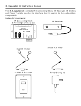
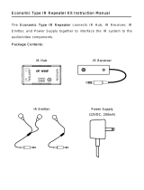
The IR Repeater Kit connects IR Connecting Block, IR Receiver, IR Emitter, and
Power Supply together to interface the IR system to the audio/video components.
Related Components:
In-Wall IR Connecting Block
In-Wall IR Receiver
Dual IR Emitter
Single IR Emitter
Switching Power Supply
In-Wall IR Connecting Block
FEATURES
1. Three emitter output connections.
2. Convenient IR confirmation LED.
3. Status power receptacle with LED indicator.
4. Power receptacle with LED indicator.
5. Large detachable IR receiver connection.
6. Mounting near audio equipment.
SPECIFICATIONS
Dimensions: 70W x114H x 40Dmm
Weight : 56g
INSTRUCTIONS
Power
Connect a 12 VDC (200mA to 1A) power supply to the power jack of the IR Connecting Block. The
red LED will be illuminated when powered. This will power all of the IR components connected to
the system. Depending on the type of components and the number of components will determine
how much current the power supply will need to provide.
Status Power
12VDC 200mA 2.1mm + Tip – sleeve.
Connect a power supply to this connection will power the status connection. The green LED will
be illuminated. This can be from a 12 volt trigger output or from a wall type power supply plugged
into a switched outlet of a stereo receiver. If you are using products like the In-Wall IR Receiver
that have a status indicator, simply plug a 12 VDC power supply into the switched outlet and when
the receiver is turned on the status LED will be illuminated.
In-Wall IR Receiver Connection
Connect the In-Wall IR Receiver to the detachable connector labeled +12VDC, GND,
STATUS, and SIGNAL.
Emitter Outputs
Connect up to 3 emitters to the emitter jacks labeled 1-3. Place the emitters on the source
equipment.

1
Dual Band In-Wall Infrared Receiver
The Dual Band In-Wall Infrared Receiver receives IR signals from a handheld IR remote control and relays
this to the audio/video equipment for operation from another room. Mounts to a single gang standard
electrical box using a decorate cover plate.
FEATURES
1. Stylish decorate design. Available in white colors.
2. Dual color LED. Green for system status and blue for talk back.
3. Ultra thin design. Mounts easily in any J-box or P-ring.
4. Wide band IR receives IR from many types of remotes.
SPECIFICATIONS
Receive Frequency Range: 34 kHz to 60 kHz
Transmit Frequencies: 38 KHz & 56 KHz
Range: 40ft. @ 38 KHz
25ft. @ 56 KHz
Power: 12VDC, 30mA max.
Status Power: 12VDC, 3mA max.
Wire requirements: 2 twisted pair, with or without shield
INSTALLATION
Connect the Dual Band In-Wall Infrared Receiver to the connecting block using 2 twisted pair wire. Use
one pair to connect GND (GROUND) and IR (SIGNAL). Use the other pair to connect ST (STATUS) and V+
(+12VDC). If the wire has a shield, connect it to the ground at both ends.
STATUS INDICATOR
To use the status indicator on the Dual Band In-Wall Infrared Receiver connect the 12 Volt 100mA or higher
power supply to the STATUS line of the connecting block as shown . Plug the power supply into the
switched outlet on the stereo receiver. When the receiver is on, the power supply will turn on the system
status line and illuminate the LED green of the Dual Band In-Wall Infrared Receiver.
MOUNTING
Mount the Dual Band In-Wall Infrared Receiver to the standard electrical box using the screws that are
supplied. Mount cover plate to the IR receiver. See Figure .

1
Dual IR Emitter
A. Standard installation
1. IR emitter attached directly to IR sensor window.
2. Most reliable activation
B. Attach emitter on
inside shelf
1. Attach emitter on shelf above or below IR sensor.
2. Less reliable activation.
C. Cabinet with door installation
1. Attach emitter on door, round shape facing the IR sensor.
2. Less reliable activation.
Note: Occasionally, more reliable activation can occur by moving the IR emitter further
away from the device. This may be due to improper placement of the emitter, or that the
sensor itself is partially obscured. It may also be due to a peculiar remote control unit /
sensor combination. Placing the emitter 5~10cm away from the IR sensor can achieve
significantly better activation in such cases. Please experiment to achieve optimal
activation before securing with the self-adhesive pads.

2
/