Page is loading ...


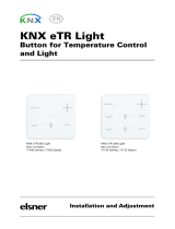
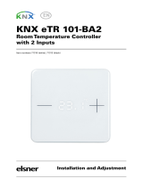
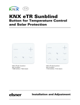
Flat & Flat 55
http://www.zennio.com Technical Support: http://support.zennio.com
2
CONTENTS
Contents ................................................................................................................................... 2
Document Updates ................................................................................................................... 3
1 Introduction ...................................................................................................................... 4
1.1 Flat / Flat 55 ............................................................................................................... 4
1.2 Installation ................................................................................................................. 6
1.3 Start-Up and Power Loss ............................................................................................ 7
2 Configuration .................................................................................................................... 8
2.1 GENERAL .................................................................................................................... 8
2.1.1 CONFIGURATION .................................................................................................... 8
2.1.2 Temperature Sensor ............................................................................................. 11
2.1.3 Backlight............................................................................................................... 11
2.1.4 Sounds ................................................................................................................. 11
2.1.5 Ambient Luminosity Sensor .................................................................................. 13
2.1.6 ADVANCED ........................................................................................................... 13
2.2 BUTTONS ................................................................................................................. 18
2.2.1 CONFIGURATION .................................................................................................. 19
2.2.2 Disabled ............................................................................................................... 22
2.2.3 Individual ............................................................................................................. 22
2.2.4 Pair ....................................................................................................................... 33
2.3 INPUTS ..................................................................................................................... 40
2.3.1 Binary Input .......................................................................................................... 40
2.3.2 Temperature Probe .............................................................................................. 40
2.3.3 Motion Detector ................................................................................................... 41
2.4 Thermostat .............................................................................................................. 42
ANNEX I. LED Illumination Modes............................................................................................ 43
ANNEX II. Communication Objects .......................................................................................... 46

Flat & Flat 55
http://www.zennio.com Technical Support: http://support.zennio.com
3
DOCUMENT UPDATES
Version
Changes
Page(s)
[1_4]_b
New devices: Flat 55 X1, Flat 55 X2 y Flat 55 X4.
-
[1.4]_a
Changes in the application program:
New functionality for individual buttons: Room State.
Optimisation of the binary inputs, thermostat,
temperature probe, motion detector, brightness and
proximity sensor modules.
32
-
[1.2]_a
Changes in the application program:
Removed button vibration function.
-

Flat & Flat 55
http://www.zennio.com Technical Support: http://support.zennio.com
4
1 INTRODUCTION
1.1 FLAT / FLAT 55
Flat / Flat 55 are a KNX multifunction capacitive touch switch from Zennio with
proximity sensor, luminosity sensor and backlighted buttons.
It is offered at a reduced size and weight, with one, two, four or six capacitive
touch buttons for Flat and one, two or four for Flat 55 (according to the user’s needs)
with LED backlight to confirm the press of the buttons as well as showing states.
Flat / Flat 55 are a fully customisable solution for the control of rooms where user
control of air conditioning systems, lighting, blinds, scenes, etc. is required.
The versatility offered by the functionality of buttons is complemented by the two built-
in analogue/digital inputs, the internal temperature sensor (only in Flat) and the
thermostat function, as well as an elegant and fully customisable design of the
front glass – customers can choose their button icons, texts and colours and even
personalise the background with their pictures, logos, etc.
The most outstanding features of Flat / Flat 55 are:
Fully customisable design of the front glass.
1 / 2 / 4 / 6 (only in Flat) touch buttons, which can operate as individual or
pair controls:
Horizontally or vertically-oriented configuration (only available for the two-
button and six-button models in Flat and for the two-button model in Flat 55).
Light indicator (LED) for every button.
Buzzer for an audible acknowledgement of user actions (with the possibility
of disabling it either by parameter or by object).
Possibility of locking / unlocking the touch panel through binary orders or
scenes.
Welcome Back object (binary or scene) which is sent to the KNX bus when
a pulsation is detected after a certain period (configurable) of inactivity.

Flat & Flat 55
http://www.zennio.com Technical Support: http://support.zennio.com
5
Built-in temperature sensor (only in Flat).
Ambient luminosity sensor for brightness automatic adjustment.
Proximity sensor for quick start.
Two analogue/digital inputs (for motion detectors, temperature probes,
additional switches, etc.).
Thermostat function.
Heartbeat or periodical “still-alive” notification.

Flat & Flat 55
http://www.zennio.com Technical Support: http://support.zennio.com
6
1.2 INSTALLATION
Figure 1 shows the connection outline of the device:
Figure 1 Schematic diagram.
Flat / Flat 55 are connected to the KNX bus through the built-in terminal (2). An
external DC power supply is not needed.
A short press on the Prog. /Test button (4) will make the device enter the
programming mode. The Prog. /Test LED (3) will then light in red. On the contrary, if
this button is held while the device gets connected to the bus, the device will enter the
safe mode. In such case, the programming LED will blink in red colour.
For detailed information about the technical features of Flat / Flat 55, as well as on
security and installation procedures, please refer to the device Datasheet, bundled
within the device packaging and also available at www.zennio.com.
1. Temperature Probe (only in Flat).
2. KNX Connector.
3. Programming LED.
4. Programming Button.
5. Attachment Clip.
6. Input Connectors (In Flat 55, the
position may vary slightly).
7. Touch Buttons.
8. Proximity and Luminosity Sensors.
3
2
7
5
4
6
1
8

Flat & Flat 55
http://www.zennio.com Technical Support: http://support.zennio.com
7
1.3 START-UP AND POWER LOSS
After download or device reset it is necessary to wait for about 2 minutes without
performing any action in order to make it possible a proper calibration of:
Proximity sensor.
Luminosity sensor.
Button presses.
For a correct calibration of the proximity and brightness sensors it is recommended not
to remain too close or place anything less than 50cm approximately and do not hit with
direct light to the device during this time.

Flat & Flat 55
http://www.zennio.com Technical Support: http://support.zennio.com
8
2 CONFIGURATION
After importing the corresponding database in ETS and adding the device into the
topology of the project, the configuration process begins by entering the Parameters
tab of the device.
2.1 GENERAL
In order to allow the device to perform the desired functions, a number of options must
be parameterized, either related to its general behaviour (horizontal/vertical
orientation, sounds, LED brightness levels…) or to advanced features (lock procedure
of the touch panel, cleaning function, welcome back object).
2.1.1 CONFIGURATION
In the "GENERAL" tab, the general settings are displayed. Most are checkboxes that
enable/disable other functionalities
ETS PARAMETERISATION
The following parameters are shown:
Device Orientation [Vertical (Normal)
1
/Horizontal (Rotated)]: allows
assigning a horizontal or vertical orientation to the device, making it easier
to identify the push-buttons during the configuration process (ETS will show a
figure with the final distribution of the push-buttons).
To prevent inconsistency in the configuration, please note the following
criterium:
Vertical (normal):
Temperature probe hole
(only in Flat) on the right
of the bottom side and the
sensors on the middle of
the top side.
Horizontal (rotated):
Temperature probe hole
(only in Flat) on the top
of the right side and
sensors on the middle of
the left side.
Figure 2 Orientation.
1
The default values of each parameter will be highlighted in blue in this document, as follows:
[default/rest of options].

Flat & Flat 55
http://www.zennio.com Technical Support: http://support.zennio.com
9
Figure 3 Main configuration.
Buttons [enabled]: read-only parameter to make it evident that the “Buttons”
tab is always enabled in the tab tree on the left. See section 2.2 for details.
Inputs [disabled/enabled]: enables or disables the “Inputs” tab in the tree on
the left, depending on whether the device will or will not be connected any
external accessories. See section 2.3 for details.
Thermostat [disabled/enabled]: enables or disables the “Thermostat” tab in
the tree on the left. See section 2.4 for details.
Heartbeat (Periodic Alive Notification) [disabled/enabled]: incorporates a
one-bit object to the project (“[Heartbeat] Object to Send ‘1’”) that will be
sent periodically with value “1” to notify that the device is still working (still
alive).

Flat & Flat 55
http://www.zennio.com Technical Support: http://support.zennio.com
10
Figure 4. Heartbeat.
Note: the first sending after download or bus failure takes place with a delay
of up to 255 seconds, to prevent bus overload. The following sendings march
the period set.
Internal Temperature Sensor (only in Flat) [disabled/enabled]: enables or
disables the “Temperature Sensor” tab in the tree on the left. See section
2.1.2 for details.
Sounds [Default/Custom]: sets whether the sound functions (button beeps,
alarm and doorbell) should work according to the pre-defined configuration or
to a user-defined configuration. See section 2.1.4 for details.
Ambient luminosity sensor [disabled/enabled]: enables setting the ambient
luminosity sensor. When the sensor is enabled, a new tab for its configuration
is shown. See section 2.1.5 for details.
Proximity Sensor [disabled/enabled]: enables the proximity sensor. This
functionality permits “waking up” the device when detecting presence.
Please refer to the specific manual “Proximity and Luminosity Sensor”
(available in the Flat / Flat 55 product section at the Zennio homepage,
www.zennio.com) for detailed information about the functionality and the
configuration of the related parameters.
Time to Consider Inactivity [1…30…255][s/min/h]: allows setting a time
after which, if no pulsation or proximity detection has occurred, the LEDs turn
off (or acquire the brightness level configured, see section 2.1.3).
Advanced Configuration [disabled/enabled]: enables or disables the
“Advanced” tab in the tree on the left. See section 2.1.6 for details.

Flat & Flat 55
http://www.zennio.com Technical Support: http://support.zennio.com
11
2.1.2 TEMPERATURE SENSOR
Flat is equipped with one internal temperature probe which can monitor the ambient
temperature of the room, thus making the device capable of reporting it to the KNX bus
and of triggering certain actions when the temperature reaches specific values.
Please refer to the specific manual “Temperature Probe” (available in the Flat product
section at the Zennio homepage, www.zennio.com) for detailed information about the
functionality and the configuration of the related parameters.
Note: as previously specified, this functionality is only available for the Flat family
models and not for the Flat 55 models.
2.1.3 BACKLIGHT
Flat / Flat 55 allow managing the brightness of the LED according to two operating
modes: normal mode and night mode.
Please refer to the specific manual “Brightness” (available in the Flat / Flat 55 product
section at the Zennio website, www.zennio.com) for detailed information about the
functionality and the configuration of the related parameters.
2.1.4 SOUNDS
It is possible to configure Flat / Flat 55 so that a brief beep is emitted as an acoustic
feedback when a button is pressed.
Enabling the button sounds can be done either by parameters or through an object,
being also possible to define in parameters if the button sounds should be initially
enabled or not.
Moreover, Flat / Flat 55 can also emit the following sounds on request (through the
corresponding communication objects) if enabled:
Doorbell sounds: a single beep.
Alarm sounds: a sequence of brief beeps with a higher pitch. The sequence
will only stop when the alarm object gets deactivated or when the user
touches any of the buttons (this, moreover the deactivation alarm, will trigger
the button action).
The range of sounds emitted will be different depending on the sound type selected.

Flat & Flat 55
http://www.zennio.com Technical Support: http://support.zennio.com
12
ETS PARAMETERISATION
In case the default button beep sound matches the requirements of the installation and
the doorbell and alarm functions are not necessary, the Sounds parameter in the
general “CONFIGURATION” tab (see section 2.1.1) can be set to “Default”. This will
also imply that the button beeps will be unconditional, as it will not be possible to
disable this function through an object.
On the other hand, if set to “Custom”, a specific tab named “Sounds” will show up in
the tab tree on the left. The initial configuration of this screen is equivalent to the
aforementioned default option. However, the following parameters will be configurable.
Figure 5. Sounds.
The default configuration of this tab is equivalent to the one mentioned above.
However, the following parameters can be customized:
Sound Type [Sound 1/Sound 2]: sets which sounds range incorporates the
device.
Disable button sound [disabled/enabled]: enables the buttons beeping. If
enabled, the following parameters will also be available:
Enable / Disable button sounds through a 1-bit object
[disabled/enabled]: makes it possible to disable / resume the button
beeping function in runtime by writing to a specific object (“[General]
Sounds – Disabling button sound”). If enabled, it will be shown:
Value [0 = Disabled; 1 = Enabled/1 = Disabled; 0 = Enabled]: allows
configuring the values (0 or 1) that will disable/resume the sounds.

Flat & Flat 55
http://www.zennio.com Technical Support: http://support.zennio.com
13
Status After ETS Download [enabled/disabled]: sets whether the button
beeping function should start up enabled or disabled after an ETS
download.
Object for Doorbell [disabled/enabled]: enables or disables the doorbell
function. If enabled, a specific object (“[General] Sounds - Doorbell”) will be
included into the project topology.
Object for Alarm Bell [disabled/enabled]: enables or disables the alarm
function. If enabled, a specific object (“[General] Sounds - Alarm”) will be
included into the project topology.
2.1.5 AMBIENT LUMINOSITY SENSOR
Flat / Flat 55 incorporate a luminosity sensor to receive and monitor ambient
brightness measurement.
Please refer to the specific manual “Luminosity and Proximity Sensor” (available in
the Flat / Flat 55 product section at the Zennio homepage, www.zennio.com) for
detailed information about the functionality and the configuration of the related
parameters.
2.1.6 ADVANCED
Independent tab for the parameterisation of some advanced functions. These functions
are explained next.
ETS PARAMETERISATION
After enabling the Advanced configuration from “General” screen (see section 2.1.1),
a new tab will be incorporated into the tree on the left.
Figure 6. Advanced.
Touch locking: enables or disables the “Touch locking” tab in the tree on the
left. See section 2.1.6.1 for details.

Flat & Flat 55
http://www.zennio.com Technical Support: http://support.zennio.com
14
Welcome back object: enables or disables the “Welcome back” tab in the
tree on the left. See section 2.1.6.2 for details.
2.1.6.1 TOUCH LOCKING
The touch panel of Flat / Flat 55 can be optionally locked and unlocked anytime by
writing a configurable one-bit value to a specific object provided for this purpose. It can
also be done through scene values.
While locked, pressing on the buttons will be ignored: no actions will be performed (and
no LEDs will change their states) when the user touches on any of the controls.
ETS PARAMETERISATION
After enabling Touch Locking in “ADVANCED” tab, a new tab will be incorporated into
the tree on the left.
Figure 7. Touch Locking.
Control of this function comprises two non-exclusive checkboxes to select how the
touch panel lock/unlock should be performed:
Figure 8. Touch Locking: Control.
Control Object: 1-Bit [disabled/enabled]: when marked, a specific drop-
down list will show up to select which value should trigger which action.
Value [0 = Unlock; 1 = Lock/0 = Lock; 1 = Unlock]: these values are
received through the object “[General] Touch Locking”.

Flat & Flat 55
http://www.zennio.com Technical Support: http://support.zennio.com
15
Scene Object [disabled/enabled]: when marked, two specific textboxes will
show up to enter the scene numbers (1 - 64) that should trigger each action.
These values are to be received through the general “[General] Scene:
Receive” object.
2.1.6.2 WELCOME BACK OBJECT
Flat / Flat 55 can send a specific object (the welcome back object) to the KNX bus
when the user presses a touch button after a significant amount of time since the last
or presence detection (when the proximity sensor is enabled). Sending it or not can
also depend on an additional, configurable condition consisting in the evaluation of
up to five binary objects.
Any actions that in normal operation may be executed will not be if the welcome back
object is sent to the bus. Thus, if the user presses a button and this causes that the
welcome back object is sent, the normal action of that button will not be triggered.
On the other hand, if the additional condition is not evaluated to true, the device will
react normally. Hence, the action corresponding to the button touch will be executed.
The welcome back object can consist in a one-bit value or a scene value (or both),
depending on the parameterisation.
ETS PARAMETERISATION
After enabling Welcome Back Object, a new tab will be incorporated into the tree on
the left.
Figure 9 Welcome Back Object.
This screen contains the following parameters:

Flat & Flat 55
http://www.zennio.com Technical Support: http://support.zennio.com
16
Timeout to Activate the Welcome Object [1…255][s/min/h]: sets the
minimum time that should elapse after the last button touch touch (or
presence detection, when the proximity sensor is enabled) before the next
one triggers the execution of the welcome back function.
Sending Trigger [Push Button/Proximity Detection]: sets whether the
welcome back object is sending after a touch in the screen or when the
proximity sensor detects presence.
Additional Condition: sets if sending the welcome back object should also
depend on an external condition. The option by default is “[No Additional
Condition]. The following are available too:
[Do not send unless all additional conditions are 0]: the welcome back
object will only be sent if all the condition objects are found to have the
value “0”.
[Do not send unless all additional conditions are 1]: the welcome back
object will only be sent if all the condition objects are found to have the
value “1”.
[Do not send unless at least one of the additional conditions is 0]: the
welcome back object will only be sent if at least one of the condition
objects is found to have the value “0”.
[Do not send unless at least one of the additional conditions is 1]: the
welcome back object will only be sent if at least one of the condition
objects is found to have the value “1”.
Figure 10 Welcome Back Object. Communication Objects.
Welcome Back Object (1-Bit) [disabled/enabled]: checkbox to enable the
sending of a 1-bit value (through “[General] Welcome back”) when the

Flat & Flat 55
http://www.zennio.com Technical Support: http://support.zennio.com
17
welcome back function is triggered and the condition (if any) evaluates to true.
The desired value should set in Value [Send 0/Send 1].
Welcome Back Object (Scene) [disabled/enabled]: checkbox to enable the
sending of a scene run request (through “[General] Scene: send”) when the
welcome back function is triggered and the condition (if any) evaluates to true.
The desired value should be set in Scene Number [1…64].

Flat & Flat 55
http://www.zennio.com Technical Support: http://support.zennio.com
18
2.2 BUTTONS
As indicated in previous sections, Flat / Flat 55 have one, two, four or six (only in Flat)
capacitive buttons (depending on the model) at the user’s disposal for the execution
of actions.
The distribution of the buttons will depend on the model, being possible to configure
them as single-button controls or in pairs by combining any two of them.
There are some differences in the button configuration depending on the model:
Flat 1 / Flat 55 X1: due to the existence of only one push button, only one
individual control is possible (two-button controls are not available).
Moreover, it can only be configured under the normal (vertical) orientation.
Figure 11 Flat 1 and Flat 55 X1
Flat 2 / Flat 55 X2: up to two one-button controls can be configured, or either
one two-button control, under any of the two orientations.
Figure 12 Flat 2 and Flat 55 X2. Normal orientation (left) and rotated (right).
Flat 4 / Flat 55 X4: up to four one-button controls can be configured, or up to
two two-button controls (by combining any two buttons for each pair). The
figure shows which number identifies each button during the configuration
process.

Flat & Flat 55
http://www.zennio.com Technical Support: http://support.zennio.com
19
Figure 13 Flat 4 and Flat 55 X4
Flat 6 (only in Flat): up to six one-button controls, or three two-button controls
(by combining any two push buttons for each pair) can be configured, under
any of the two orientations. The figure shows which number identifies each
button during the configuration process.
Figure 14 Flat 6. Normal orientation (left) and rotated (right).
2.2.1 CONFIGURATION
The following is a list of the functions that can be assigned to each button.
Disabled (the button will not react to user presses).
Pair A, B or C (the number of available pairs depends on the selected
model), being the function of such pair one of the following:
Switch (binary).
Two objects (short press /
long press).
Light dimmer.
Shutter.
Individual (one-button control):
Switch (Binary).
Hold & release.
Two objects (short press /
long press).
Scene.
Scaling constant.
Counter constant.
Float constant.
Light dimmer.
Shutter.

Flat & Flat 55
http://www.zennio.com Technical Support: http://support.zennio.com
20
LED indicator. Room State
Apart from the button function itself, the desired behaviour of the button LEDs can be
set. The different illumination modes have been detailed in ANNEX I. LED Illumination
Modes.
The next sections explain the configuration involved for each of the above functions.
ETS PARAMETERISATION
An independent tab for the parameterisation of the buttons is shown in ETS by default,
initially containing only a sub-tab named Configuration.
Figure 15 Buttons - Configuration
One drop-down list with the following options is shown per button:
[Disabled]. See section 2.2.2 for details.
/