Page is loading ...

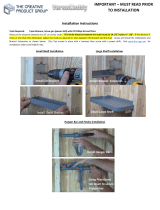
INSTALLATION INSTRUCTIONS
GUÍA DE INSTALACIÓN
Read all instructions carefully before proceeding.
SAVE THIS GUIDE FOR FUTURE REFERENCE.
Leer detenidamente todas las instrucciones antes de
comenzar la instalación
CONSERVAR ESTE MANUAL COMO REFERENCIA.
Serial numbers • Números de serie
IMPORTANT • Record the serial numbers
IMPORTANTE • Registre el número de serie
A two person installation is required.
Se recomienda realizar la
instalación entre dos personas
TUB SHOWER INSTALLATION (3 WALLS)
INSTALACIÓN DE BAÑERA DUCHA (3 MUROS)
HARDWARE INCLUDED
IN BOXES
HARDWARE INCLUIDO EN
LAS CAJAS
OPEN ALL BOXES
BEFORE YOU START
ABRIR TODAS LAS CAJAS
ANTES DE EMPEZAR
Ver video de instalación -
Escanear código QR con un
dispositivo móvil.
View Installation Video - Scan
QR code with a mobile device

Table of contents: Page
Tools and supplies.............................................................................................................. 3
Parts and components........................................................................................................ 4
1. Building the structure..................................................................................................... 6
2. Installing the bathtub...................................................................................................... 7
3. Installing Ulok system on the walls............................................................................... 9
4. Temporary installation of the back wall........................................................................... 10
5. Temporary installation of the side walls...........................................................................11
6. Final installation of back wall.......................................................................................... 14
7. Final installation of side walls......................................................................................... 15
8. Marking and drilling the glass shelf holes..................................................................... 16
9. Silicone............................................................................................................................17
10. Glass shelf installation.................................................................................................. 17
11. Wall fi nish......................................................................................................................19
12. Warranty........................................................................................................................ 36
Table de matières: Page
Herramientas y materiales.................................................................................................. 3
Piezas y componentes........................................................................................................ 4
1. Construcción de la estructura......................................................................................... 20
2. Instalación de la bañera................................................................................................. 21
3. Instalación del sistema Ulok sobre los muros................................................................. 23
4. Instalación temporal del muro posterior.......................................................................... 24
5. Instalación temporal de los muros laterales................................................................... 25
6. Instalación fi nal del muro posterior................................................................................. 28
7. Instalación fi nal de los muros laterales........................................................................... 29
8. Marcado y la perforación de agujeros para la repisa...................................................... 30
9. Silicona............................................................................................................................31
10. Instalación de la repisa................................................................................................. 31
11. Acabado del muro......................................................................................................... 33
12. Garantía........................................................................................................................ 36
For installation steps in
ENGLISH
ENGLISH
go to page 6
Para las etapas en ESPAÑOL ir a la pagina 20

3
Screwdriver
Destornillador
TOOLS
REQUIRED
HERRAMIENTAS
REQUERIDAS
24" level min.
Nivel de 24" min.
Pencil
Lápiz
Clear silicone sealant
Sellador de silicona
transparente
Measuring tape
Cinta métrica
18" square min.
Escuadra de
18" min.
Utility knife
Cuchillo multiuso
Safety equipment
Equipo de
seguridad
Hole saw
Sierra de
perforación
1/8" drill bits
Brocas de 1/8
SUPPLIES
SOLD SEPARATELY
SUMINISTROS
VENDIDOS POR SEPARADO
Box of #8x1¾"
flathead screws
Caja de tornillos #8x1¾"
de cabeza plana
Wood shims
Cuñas de madera
50
Electric drill
Taladro eléctrico

4
PARTS PIEZAS
6
1
43
2
109
8
5
11
# Part Pieza Qty/Cant. Code/Código
1 X fastener Sujetador en forma de X 8
10060303
2
#8 x 1¼’’ Screw (for X fastener) Tornillos #8 x 1¼’’ (Para sujetador en X) 8
3 Retraction pin Pasador de retracción 8
4
#8 x ⅜ Screw (for retraction pin)
Tornillos #8 x ⅜ (para
pasador de retracción)
8
7
# Part Pieza Qty/Cant. Code/Código
5 Glass shelf Repisa 1
10060011
6 Bracket Soporte de repisa 2
7
#10 x 2’’ screws Tornillos #10 x 1½’’ (repisa) 2
8
Plastic washer Adandela en plástico para repisa 2
9
Support cap Tapa de la fi jación de repisa 2
10 #10 x ½ screws Tornillos #10 x ½ (para repisa) 2
11
Allen key Llave allen 1
12 Template Plantilla de perforación 1
# Part Pieza Qty/Cant. Code
13 Bathtub Base 1 -
14 Back wall Muro posterior 1 -
15 Side Wall Muro lateral 2 -
PARTS INCLUDED IN PARTS PACK | PIEZAS INCLUIDAS EN PAQUETE DE PIEZAS
PARTS INCLUDED IN SHELF PACK | PIEZAS INCLUIDAS EN LA CAJA DE LA REPISA
12
Inside the box
En el interior de la caja
COMPONENTS COMPONENTES
www.maax.com
1
0
06
0
3
03 –
U
LO
K
Sk
in
p
ac
k f
o
r
U
t
il
e
-
1
ju
n
ct
io
n
3
1
2
4
B
A
CK
W
A
L
L
M
UR
AR
R
I
ÈR
E
MUR
O POST
E
R
IO
R
I
NSIDE VIEW
VUE
I
NT
ÉR
I
EUR
E
VIS
T
A
INTERIO
R
S
I
D
E
WALL
M
UR
DE
CÔ
T
É
M
U
R
O
L
A
TE
R
A
L
3
4
I
NS
I
D
E VIEW
V
U
E
I
NT
ÉR
I
EU
RE
VI
S
T
A
I
NT
E
RI
O
R
by
/
p
ar
M
A
A
X
*
Extr
a
pa
r
ts
a
r
e
inc
l
u
d
e
d
in
th
i
s
p
ac
k
in c
a
s
e
of lo
ss
or
dama
g
e
*
Des piè
c
es
supp
l
émen
t
air
e
s son
t
i
n
c
luse
s e
n ca
s d
e perte ou
b
r
is
* Piez
a
s ext
r
as están inclui
d
as en e
st
e e
m
pa
q
u
e
en c
a
so d
e
per
d
id
a o
daño
www.maax.com
1
0
0603
0
3
–
ULO
K
Skin
p
ack
f
o
r
U
til
e
-
1
jun
ct
i
on
3
1
2
4
BACK
W
ALL
M
U
R
ARR
I
ÈRE
M
U
R
O P
OSTE
R
IO
R
INS
IDE
VIE
W
VUE INTÉRIE
U
RE
VIS
T
A
INTERIOR
SIDE
W
A
LL
M
UR
DE
CÔ
T
É
M
UR
O
L
A
TE
R
A
L
3
4
INSI
DE
VI
EW
VUE
IN
TÉ
R
IE
URE
VI
S
T
A
I
N
T
ER
I
O
R
by
/par
M
AA
X
* Extra p
a
rts are included
i
n
this pack in c
ase
of
l
o
ss or dam
ag
e
* Des p
i
è
c
es supp
l
émen
t
aires
s
on
t
in
cl
u
ses
en
cas de perte ou br
i
s
*
Piez
as
extras están incl
u
i
da
s e
n
e
st
e e
m
pa
q
u
e
en c
a
so
d
e
pe
rdi
d
a o da
ñ
o

5
13
14
15
15
4
15
3
INSIDE VIEW
VISTA INTERIOR
5
9
10
8
7
6
1
2
14
OVERVIEW VISTA GENERAL

6
1
STEP Building the structure
Build a structure based on the dimensions in the chart
below.
IF STRUCTURE IS ALREADY BUILT CHECK THAT
IT RESPECTS THE DIMENSIONS BELOW
Verify the wall studs are square, plumb and the
fl ooring is perfectly level.
6"
6"
C
For a worry free installation follow
all instructions and check them off
as you go.
A
B
C
D
Top view of structure
1.1
Check me!
1.2
Check me!
1.3
Check me!
D
COMPATIBLE BATHTUBS No A B C D
COCOON 6030 IFS 105822
Between
60" - 60 1/4"
31 1/2"
min.
14 1/8" 9 3/8"
BROME 105821
Between
60" - 60 1/4"
31 1/2"
min.
14 1/8" 9 3/8"
EXHIBIT 6030 (IFS) 105519 59 3/4"
30"
min.
14" 10"
EXHIBIT 6030 (IFS) AFR 105511 59 3/4"
30"
min.
14" 10"
NEW TOWN 6030 IFS 105454
Between
60" - 60 1/4"
31 1/2"
min.
14" 10 1/8"
RUBIX 6030 105815 59 3/4"
30"
min.
18 3/8" 15"
RUBIX 6030 AFR 105816 59 3/4"
30"
min.
20 3/8" 15"
Leveling the fl oor is
critical for wall alignment
Quick tip
For leveling the fl oor use self-leveling
mortar.
Cut out an approximate 6" x 6" opening around
the drain center outlined by measurements C and
D. See image to the right and the chart above. We
recommend that a plumber completes the drain pipe
connection.
Before starting make sure to have all
parts and components refer to page 4.

7
2
STEP Installing the bathtub
Install the bathtub (13) pushing it completely against
the back studs. Center the bathtub left to right inside
the alcove leaving equal spacing on both sides.
13
Leveling the bathtub is
critical for wall alignment
Verify that the bathtub is completely level on all sides.
Confi rm that the drain pipe is centered. We
recommend that a plumber completes the drain pipe
connection.
Centering the bathtub left to right is
critical for side wall installation.
13
Top view
Flush
2.1
Check me!
2.2
Check me!
2.3
Check me!
Studs
Connect plumbing (drain, overfl ow, faucets, etc.) ac-
cording to local standards and to general rules in the
bathtub installation guide. Make sure that all joints are
waterproof.
2
Remove clear plastic fi lm on the bathtub. Use
cardboard on the bathtub fl oor as protection until
the installation is complete.

8
If needed use wood shims between the studs and
the fastening fl ange to maintain centered position of
bathtub.
DO NOT USE SHIMS UNDER THE BATHTUB TO
LEVEL!
DOING SO WILL VOID THE MAAX WARRANTY!
13
With a 1/8" bit, drill holes in the bathtub fastening
fl ange then secure the bathtub to all the wall studs
with #8 x 1¾ " screws (not included). Only pre-drill
the flange not the studs.
HAND TIGHTEN ONLY !
CUT SHIM EXCESS
13
2
STEP Installing the bathtub (cont'd)
2.4
Check me!
2.5
Check me!
Ø 1/8"
Fastening fl ange

9
3
STEP Installing Ulok system
on the walls
Install three X fasteners (1) on each side of the back wall
(14) in the pre drilled holes using the screws provided (2).
Quick tip
There is a positioning pin on X
fastener so they can only be
installed one way.
14
Back wall
1
14
2
2
1
14
This side
down
4
3
The side walls are interchangeable.
For left wall install the pins on the
right side, for the right wall install the
pins on the left side.
Quick tip
Side walls
15
15
Fastening fl ange
3.1
Check me!
3.2
Check me!
This side down
Positioning
pin
The Ulok system parts are in the
side wall boxes. (1 pack per box)
ww
w
.m
aax
.
c
om
10
0
60303 –
U
L
OK
Sk
i
n
p
ac
k
f
or
U
t
i
le
-
1
j
u
n
c
tion
3
1
2
4
BA
CK
W
A
L
L
MUR
A
RR
I
ÈRE
M
U
R
O
P
O
S
T
E
R
IO
R
IN
SI
D
E
V
I
EW
VUE I
NT
É
R
I
E
UR
E
V
I
S
T
A
IN
T
E
RI
OR
S
I
D
E
W
ALL
MU
R
D
E
CÔTÉ
MU
R
O
L
A
TE
R
A
L
3
4
I
N
S
I
D
E
V
I
EW
VUE
I
NT
ÉRI
E
U
R
E
V
IS
T
A
I
NT
E
R
I
O
R
by/
p
a
r
M
A
A
X
* Ext
ra
p
a
r
t
s
are
in
c
l
ud
e
d
in
t
h
is
pa
ck
in
c
a
s
e
o
f
l
os
s or
damage
*
D
es
p
ièces
su
pp
lé
m
en
t
a
ir
e
s
s
o
n
t
inclu
s
e
s
en c
as de
p
ert
e
ou
b
ris
* P
ie
z
as
ex
t
ra
s
e
s
t
á
n
in
c
lu
id
a
s
e
n
e
s
t
e
emp
a
que
e
n
c
a
s
o
d
e
p
e
r
di
d
a
o
d
año
ww
w.
maax
.
com
1
0
0
6
0
3
0
3
–
U
LOK
Sk
in
p
ac
k
fo
r
U
ti
le
-
1
ju
n
cti
o
n
3
1
2
4
BA
CK
W
ALL
M
UR
A
R
RIÈ
RE
M
U
R
O
P
OS
T
E
R
I
O
R
I
NS
I
D
E
V
I
E
W
V
U
E I
N
T
É
RI
E
UR
E
VI
S
T
A
I
NT
E
R
I
O
R
S
I
D
E
W
A
LL
M
UR
D
E
CÔ
T
É
M
U
R
O
L
A
T
E
R
A
L
3
4
I
N
S
I
D
E VIE
W
V
UE
I
N
T
ÉR
I
EU
R
E
V
I
S
T
A
INT
ERI
O
R
by
/
par
M
AA
X
*
Ext
ra
part
s
ar
e
i
nclude
d
i
n
this
pa
ck
in
c
a
s
e o
f
lo
s
s
o
r
d
amag
e
*
D
es
piè
c
es s
upp
lémentair
e
s
s
o
nt inc
l
use
s
e
n
c
a
s
de
pe
rte
o
u b
ris
*
Piez
a
s
e
x
tras
e
stá
n
inclu
id
as
en es
te
e
m
p
aq
u
e
en c
aso d
e
p
erd
i
d
a o da
ñ
o
Fasten 3 retraction pins per side wall in the pre drilled
holes with the screws provided (4) to the left-hand or right-
hand fastening fl ange of the side walls (15) depending on
which side the wall will be installed on.

10
4
STEP Temporary installation of the back
wall
Quick tip
Installing the walls temporarily will
ensure proper wall alignment before
permanent installation.
Make sure the wall is plumb and
centered on the bathtub.
With a 1/8" bit, drill holes in the back wall fastening
flange (14) at the top aligned with each stud. Only pre-
drill the flange not the studs. Then, secure the back
wall (14) with one #8 x 1¾" screw (not included) in one
of the pre-drilled holes.
IMPORTANT: HAND TIGHTEN ONLY. TEMPORARY
INSTALLATION.
Quick tip
Push the bottom of the back wall
with your foot when fastening in
place.
Plumbing the back wall is
critical for alignment of the
side walls
14
Bathtub
deck
Back wall
Position and level the back wall (14) by sitting it on the
deck at the back of the bathtub.
4.1
Check me!
4.2
Check me!
4.3
Check me!
Pull back the protective fi lm on the walls (14-15) at least
3" away from all edges. Keep the remaining protective
fi lm on the walls and base.
min.3/16"
max.3/8"
Stud
X fastener

11
Install the side wall (15) on the opposite side of the
faucet installation. Lift the wall approximately 3" above
the deck of the bathtub, push it completely against the
back wall then lower the side wall into position.
The side wall should now line up
with the front of the bathtub.
Quick tip
Bathtub
Side wall
With a 1/8" bit, drill holes in the side wall fastening flange
(15) at the top aligned with each stud. Only pre-drill
the flange not the studs. Then, secure the side wall
(15) with one #8 x 1¾" screw (not included) in one of the
pre-drilled holes.
IMPORTANT: HAND TIGHTEN ONLY. TEMPORARY
INSTALLATION.
3
1
Side wall
Back wall
It is critical that all 3 retraction pins
engage with the X fasteners. There
should be no gap between the walls.
5
STEP Temporary installation of the side walls
Quick tip
Place a level vertically
on the side wall. If the
wall is not straight,
make sure that the
retraction pins are
properly inserted in
the X fasteners.
5.1
Check me!
5.2
Check me!
15

12
5
STEP Temporary installation of the
side walls (Cont'd)
Measure the distance between the front face of the back
wall (14) and the center of the faucet. Then measure the
distance from the top of the bathtub deck to the center of
the faucet.
Quick tip
Hole saws can be rented at your
local hardware store or any tool
rental location.
Faucet
center
Using those two measurements mark the position of the
faucet hole on the remaining side wall. Measure from the
side and bottom of the side wall where the retraction pins
are installed.
Repeat this process for all required faucet holes.
5.4
Check me!
5.3
Check me!
5.5
Check me!
Back
wall
Top view
Bathtub
deck
Front cut
view
For safe hole saw usage always
pre-drill a hole and wear safety
glasses when drilling.
Drill a hole from front for the faucets at the previously
marked positions. Pre-drill the hole with the ⅛'' drill bit.
The hole saw size is determined by the faucet type; refer
to the faucet installation manual for hole saw size.
Measure twice, drill once !
Record measures below.

13
Install the side wall (15) with the drilled faucet hole(s).
Lift the wall approximately 3" above the deck of the
bathtub, push it completely against the back wall then
lower the side wall into position.
Quick tip
With a 1/8" bit, drill holes in the side wall fastening flange
(15) at the top aligned with each stud. Only pre-drill
the flange not the studs. Then, secure the side wall
(15) with one #8 x 1¼" screw (not included) in one of the
pre-drilled holes.
IMPORTANT: HAND TIGHTEN ONLY. DO NOT
OVER-TIGHTEN THE SCREW.
3
1
Side wall
Back wall
Bathtub
Side wall
5
STEP Temporary installation of
the side walls (Cont'd)
The side wall should now line up
with the front of the bathtub.
Quick tip
Place a level
vertically on the side
wall. If the wall is not
straight, make sure
that the x-fasteners
are properly inserted
5.6
Check me!
5.7
Check me!
It is critical that all 3 retraction pins
engage with the X fasteners. There
should be no gap between the walls.
Deck

14
6
STEP Final installation of back wall
Quick tip
Hold the bottom of the back wall
with your foot when fastening in
place.
13
13
⅜"
Bathtub
Back
wall
14
min.3/16"
max.3/8"
Stud
X fastener
It is critical for the side wall
installation for there to be at least
⅛'' and no more than ⅜" between
the stud and the X fastener.
6.1
Check me!
6.3
Check me!
6.4
Check me!
Remove all walls from the structure.
Clean the bathtub and apply a bead of silicone on the
deck at 3/8" from the back fastening flange. Run the
bead of silicone the entire length of the bathtub and 1''
on each side as well.
6.2
Check me!
Apply a bead of silicone on both sides of base (13) thres-
hold at 3/8" from the base side fastening flanges.
Apply silicone on both side of the back wall (14) just
before the wall side radius. The silicone applied on the
base and vertically on the back wall must overlap.
Secure the wall to the wall studs with #8 x 1¾ "
screws (not included) in the previously drilled holes.
Also, secure the wall by the fastening fl anges on the
side of the wall. Use the pre-dilled holes.
If needed, use shims to keep wall plumb, square
and leveled. (Cut shim excess)
IMPORTANT: HAND TIGHTEN ONLY. DO NOT
OVER-TIGHTEN THE SCREWS.
⅜"
⅜"
1"

15
Install the side wall (15) opposite the faucet. Lift the
wall approximately 3 inches above the deck of the
bathtub, push it completely against the back wall then
slide the side wall into position.
WIPE OFF EXCESS SILICONE
3
1
Side wall
Back wall
7
STEP Final installation of side walls
Install the side wall (15) with the faucet hole. Lift the
wall approximately 3 inches above the deck of the
bathtub, push it completely against the back wall then
slide the side wall into position.
WIPE OFF EXCESS SILICONE
3
1
Side wall
Back wall
7.1
Check me!
7.2
Check me!
7.3
Check me!
BEFORE CONTINUING,
VALIDATE THAT ALL
THE WALLS ARE LEVEL,
PLUMB AND SQUARE

16
7
STEP Final installation of side walls (cont'd)
Secure the walls to the wall studs with #8 x 1¾ "
screws (not included) in the previously drilled holes.
Also, secure the walls by the fl anges on the sides of
the walls. Use the pre-dilled holes.
If needed, use shims to keep walls plumb, square
and leveled. (Cut shim excess)
IMPORTANT: HAND TIGHTEN ONLY. DO NOT
OVER-TIGHTEN THE SCREWS.
Check me!
Place the template in the corner of the shower where
you want to install your shelf.
Slide the template up until the points on the left and
right-hand side of the template are at the height you
want your shelf.
Use a pencil, marker or wax pencil to mark the spots
where the holes for the shelf will be drilled.
Drill the holes using a 9/64" drill bit.
8
STEP Marking and drilling the
glass shelf holes
Fold here
Drilling positions
Bathtub
Side wall
THE SIDE WALLS SHOULD LINE UP WITH
THE BATHTUB
Quick tip
90°
7.4
Check me!

17
Quick tip
Apply masking tape on both sides
of the joint where you will run a
bead of silicone. Apply the silicone,
smooth with a wet fi nger then
remove the masking tape.
Check me!
Apply a bead of silicone all along the wall to wall
and wall to base joints. For a smooth fi nish you can
remove the silicone excess with a damp rag or wet
fi nger.
9
STEP Silicone
Apply silicone in the previously drilled holes on the side
and back walls. Apply silicone to the rear of the shelf
brackets (6).
Fasten the brackets in place using the screws (7).
10
STEP Glass shelf installation
7
6
6
10.1
Check me!
All faucets installed on the walls
must be sealed with silicone.
Remove protective fi lm from walls
When installing the faucet
faceplate or any other
component, be sure to
silicone the outer edge.

18
Clean the top rubber part of the brackets with a damp
cloth, then place the glass shelf (5) over the brackets (6).
5
6
6
Insert the washers (8) in the shelf support cap (9). Align
and insert the shelf support caps (9) with the holes of
the glass and the holes of the shelf brackets (6). Screw
from the bottom of the shelf with the # 10 x ½'' screws
(10) and tighten by hand with the Allen key (11).
9
10
6
8
11
7
10
STEP Glass shelf installation (cont'd)
Quick tip
If you can read the MAAX logo, the
shelf is installed on the right side.
Align oblong holes
10.2
Check me!
10.3
Check me!
Do not overtight the support cap (9)

19
For the wall fi nish you can install install your fi nishing
material on top of the fl ange or on the wall edge as shown.
11
STEP Wall fi nish
Check me!
Finishing
material
Finishing
material

20
6"
6"
C
D
A
B
C
D
BAÑERAS COMPATIBLES No A B C D
COCOON 6030 IFS 105822
Entre
60" - 60 1/4"
31 1/2"
min.
14 1/8" 9 3/8"
BROME 105821
Entre
60" - 60 1/4"
31 1/2"
min.
14 1/8" 9 3/8"
EXHIBIT 6030 (IFS) 105519 59 3/4"
30"
min.
14" 10"
EXHIBIT 6030 (IFS) AFR 105511 59 3/4"
30"
min.
14" 10"
NEW TOWN 6030 IFS 105454
Entre
60" - 60 1/4"
31 1/2"
min.
14" 10 1/8"
RUBIX 6030 105815 59 3/4"
30"
min.
18 3/8" 15"
RUBIX 6030 AFR 105816 59 3/4"
30"
min.
20 3/8" 15"
Verifi car que los listones esten a escuadra y verticales
y que el piso este a nivel.
En las bases con espuma reforzada
(Olympia), utilizar mortero autonive-
lante para nivelar el piso.
Para una instalación sin problemas
siga las etapas una a una y vaya y
marquelas una vez estén terminadas.
Corte una abertura de aproximadamente 6 x 6 para
el desagüe central, siguiendo las medidas C y D. Ver
la imagen de la derecha y de la tabla en el paso 1.1.
Recomendamos contratar a un plomero certifi cado
para conectar el desagüe.
Vista superior de la estructura
Es esencial que el suelo
esté a nivel para garanti-
zar la verticalidad de las
paredes a instalar.
1.1
Marcarme!
1.2
Marcarme!
1.3
Marcarme!
1
ETAPA Construcción de la
estructura
Contruir una estructura que respete las dimensiones
mencionadas en la tabla.
SI LA ESTRUCTURA YA ESTA CONSTRUIDA,
ASEGURARSE QUE LAS DIMENSIONES
RESPETEN LAS DE LA TABLA
Cti t t tl di i
Antes de comenzar asegurese de tener
todas las piezas y componentes
referirse a la página 4.
/