Extron USFM 100 User manual

Category
Projector mounts
Type
User manual

This manual is also suitable for

1
IMPORTANT:
Go to www.extron.com for the
complete user guide, installation
instructions, and specifications.
USFM 100 • Installation Guide
IMPORTANT SAFETY INSTRUCTIONS
Read all instructions before starting installation.
When using this accessory, basic precautions should always be followed, including the following:
CAUTION: Risk of Personal Injury. Maximum setup load for the USFM 100 (projector arm) is 40 lbs (18.1 kg).
ATTENTION : Risque de blessure grave. La charge maximum d'installation pour le USFM100 (le bras du projecteur)
est 18,1kg (40lbs).
SAVE THESE INSTRUCTIONS
NOTE: Refer to local building standards and codes to verify that the installation will meet the regulatory requirements.
Observe all local and national building and safety codes, UL requirements, and ADA accessibility guidelines.
CAUTION: Risk of Personal Injury or Property Damage. Do not exceed specified weight limits of any component of
the installation. Follow the manufacturer's specifications and installation instructions.
ATTENTION : Risque de dommages corporels ou matériels. Ne dépassez pas les limites de poids de n'importe quel
composant de l'installation. Suivez les spécifications et les instructions d'installation du fabricant.
The Extron USFM 100 is a mounting kit for suspending ultra short throw projectors from a wall. The USFM 100 base
plate enclosure is capable of mounting a PoleVault
®
System switcher and its supplied power supply, with sufcient room
remaining for installing additional devices and cable management. It is designed to be used with the UPB 125 universal
projector bracket (supplied with the Extron WallVault
®
system).
The USFM 100 has knockouts on all four sides that allow external raceways or conduits to be attached for cabling runs
where necessary.
Extron
USFM 100
Plastic Enclosure Cover
Boom Arm
Base Plate
Arm Cover (bottom)
Arm Cover (top)
Arm Cover (front)
Device Mounting Plate
Figure 1. USFM 100 Parts
2
USFM 100 • Installation Guide (Continued)
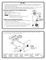
Hardware Included in the Kit
Parts Qty Application
¼ - 20 x 2 inch, pan head bolts 4 Base plate to wall installation
¼ inch toggle assembly 4 Base plate to wall installation
¼ inch metal washers (47/64 inch O.D.) 8 Base plate to wall installation
5/16 x 3 inch lag screws 4 Base plate to wall installation
5/16 inch metal washers (11/32 inch I.D., 11/16 inch O.D.) 4 Base plate to wall installation and boom arm
¼-28 x 3/4 inch screw 1 Securing boom arm (top)
¼-20 x 1/2 inch button screws 4 Securing boom arm (extension)
10-32 x 3/8 inch pan head screws 2 Securing boom arm (bottom)
10-32 x ¼ inch set screw 1 Securing projector pipe
6-32 x ¼ inch button screws 12 Securing covers for boom arm (10)
Securing device mounting plates
6-32 x ½ inch button screws 4 Securing plastic covers for enclosure
Tie wraps 4 Securing power supply wires
4-40 x ¼ inch pan head screws 4 Securing switcher to plate
Installation
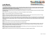
CAUTION: Risk of Personal Injury or Property Damage. Before commencing installation, the wall structure must
be examined to determine if it is suitable for the proper installation and support of this product. If needed, the
installer should reinforce the wall. Drywalls should have a minimum thickness of 1/2 inch and a maximum thickness
of 5/8 inch. Improper installation of this product could lead to serious injury.
ATTENTION : Risque de dommages corporels ou matériels. Avant de commencer l'installation, la structure du
mur doit être examinée afin de déterminer si elle est appropriée pour l'installation et la prise en charge correctes
de ce produit. Si nécessaire, l'installateur devra renforcer le mur. Les murs en plaque de plâtre doivent avoir une
épaisseur minimum de 2,54cm (1/2inch) et une épaisseur maximum de 12,7cm (5/8inch). Une installation non-
conforme de ce produit peut engendrer des blessures graves.
The location and type of wall where the USFM 100 is to be installed should be identied before starting installation. This
determines the installation method and the type of fasteners used to secure the plate to the wall.
Recommended Installation Tools
• Level (24 inch) • Ladder • Tape measure • Stud nder
• Drill and drill bits • Phillips screwdriver • Allen hex wrench (5/64 size)
1. Mount the Base Plate
NOTE: Before installation, see the user manual for the display device to determine the proper location and
placement of the mount. Take into consideration the projector lens offset, screen size, screen aspect, and
projected image throw distance. See page 8 for the dimensions of the USFM 100 (with the projector pipe and
UPB 125 attached) to aid in this determination.
a. At the desired site, use an edge-to-edge stud nder to locate the center of the wall studs (wood or steel). Mark
each stud location. Minimum stud size should be 2 inches by 4 inches.
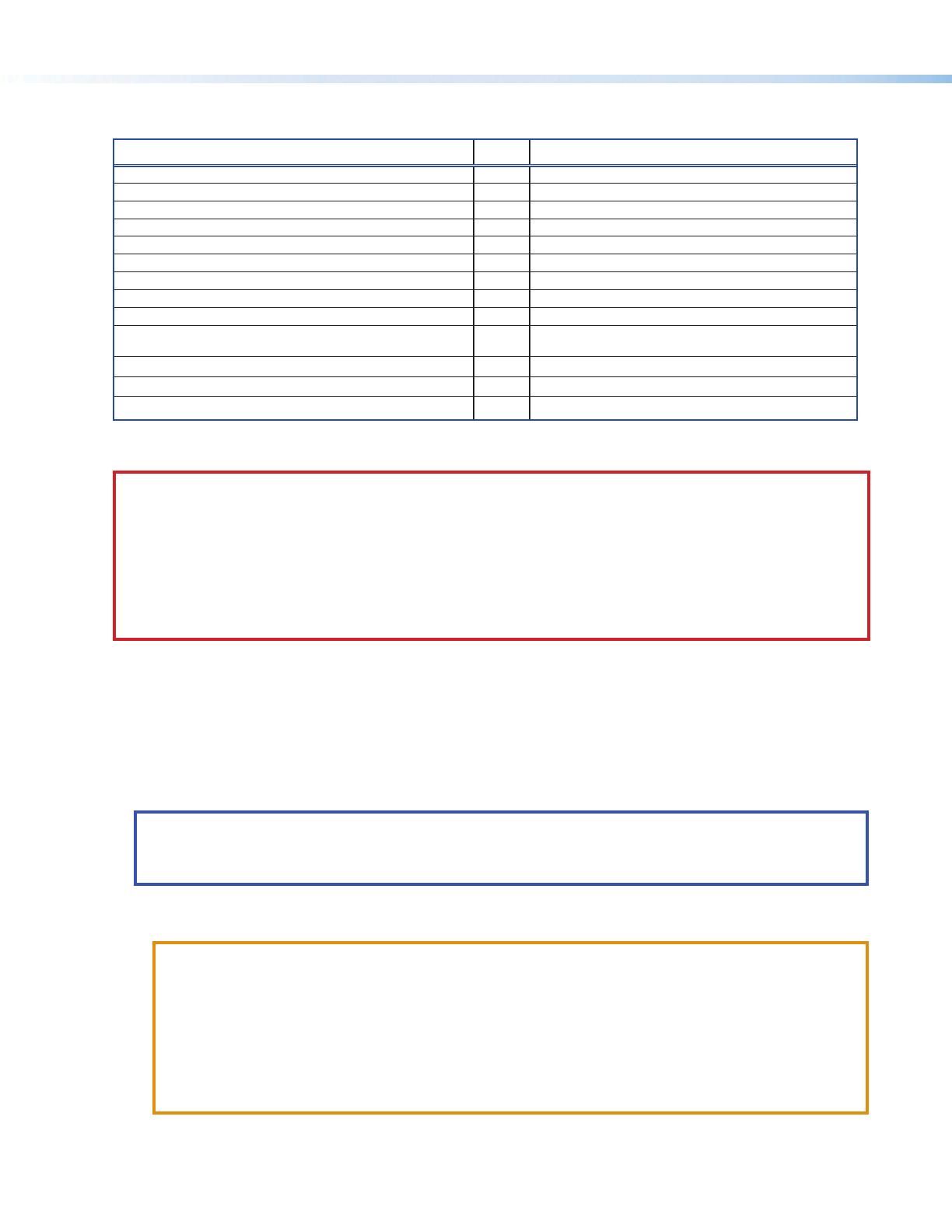
ATTENTION:
Potential Damage to Property. For secure installation, it is required to attach the base plate to two
wall studs, using a minimum of four securing points. Drywall toggles can be used for holes that are
not aligned with studs (see figure 3 on next page). This product is not intended to be mounted solely to
drywall.
Possibles dégâts matériels: Afin de sécuriser l’installation, il est nécessaire de fixer la base a deux
poteaux muraux en utilisant au moins 4 points de fixation. Des chevilles à bascules adaptées à la cloison
peuvent être utilisées si les percements ne sont pas alignés sur le support (vior figure 3» en page
suivante). Ce produit n’est pas conçu pour être monté directement sur une cloison sèche.
b. Hold and level the base plate against the wall. Mark a minimum of four positions (two top, two bottom) using either
the mounting slots or the keyholes (slots uppermost) that are on the stud lines (see the + marks in figure 2 on next
page). Where applicable, mark the mounting holes on the wall for drywall toggles.
3
Level
Cutout for
Signal Cable
Access
Marker for
Pilot Hole
USFM 100
Base Plate
Mounting
Holes
Signal Cables
Exiting from
Cutout
Figure 2. Wall Mounting Features
c. If the cables are to be run behind the wall to the USFM 100 location, mark the cutout area on the wall large enough
for signal cables (see inset in gure 2).
d. Remove the base plate and set it aside. Cut out the marked area for cable access.
For drywall with wood studs
i. Drill ¼ inch (6.35 mm) pilot holes at the marked stud locations.
ii. Align the base plate mounting holes over the pilot holes and lightly secure with 5/16 inch lag screws and washers.
NOTE: If using toggle screws for assembly, follow the installation method (steps A through D) shown in
figure3.
A. Grasp plastic handle, collapse
toggle and insert into wall.
B. Slide plastic washer
down into pilot hole.
C. Cut off plastic handle close
to wall.
D. Hand screw in pan head bolt
until 1/8 inch gap remains.
Figure 3. Steps for Toggle Assembly Installation
iii. Verify level and position, and fully tighten down all the screws to secure the plate ush to the wall.
For drywall with steel studs
i. Drill a ½ inch (13 mm) hole through the stud at each of the locations (four recommended).
ii. Insert the supplied toggles through the studs and lightly secure the plate using the four supplied
(¼-20 x 2 inch) bolts and washers.
iii. Verify level and position, and fully tighten down all the bolts to secure the plate ush to the wall.
figure 2
A. Grasp plastic handle, collapse
toggle and insert into wall.
B. Slide plastic washer
down into pilot hole.
C. Cut off plastic handle close
to wall.
D. Hand screw in pan head bolt
until 1/8 inch gap remains.
4
2. Mount the Switcher
a. Place the mounting plate at on the switcher base with the two small raised tabs on top, and the small securing
tab over the front panel. Align the two mounting holes in the switcher base with the corresponding holes on the
mounting plate. Secure the plate to the switcher using the two 4-40 x ¼ inch pan head screws.
b. Secure the mounting plate (and switcher) to the base plate by aligning the two small tabs on the back of the
mounting plate over the corresponding tabs on the base plate (see gure 4, inset). Slide the mounting plate (and
switcher) down into place. Secure it to the base plate by passing a 6-32x¼ inch screw up through the securing tab
(see gure 4). Tighten down the screw.
(1) 6-32 x 1/4"
Screw
(2) 4-40 x 1/4"
Screws
Mounting Plate
Securing
Tab
USFM 100 Base Plate
LAN 1 LAN 3
LAN 2 LAN 4
L R
DO NOT
GROUND
OR SHORT
SPEAKER
OUTPUTS
4/8
Ω
- - A MAX
POWER
12V
HDMI
HDMI
1/2
SIG
LINK SIG LINK
3/4
5
6
INPUTS
OUTPUT
AUDIO OUT
PVS 407D
AMPLIFIED AUDIO OUT
PAGING
SENSOR
PVT IN
PVT IN
L
R
AUX
OVER PVT
REMOTE
VOICELIFT
LAN
INPUT 7
+V
L
R
RS-232
Tx Rx
IR
S GG
CLASS 2 WIRING
LAN
PVS 407D
Switcher
Figure 4. Attach Switcher to Mounting Plate and Secure to Base Plate
3. Run Cables
NOTE: All cable installation should be performed in accordance with local and national building codes, fire and
safety codes, and local and national electrical codes.
Run signal cables from the PoleVault input wallplates, control device location, and the speakers to the USFM 100
location. Cables can be routed behind the walls, through a surface raceway (such as Wiremold 700 or 2400), or
through conduit directly to the USFM 100.
If running cable behind the walls:
a. Run all the cables from all the locations to the USFM 100 and through the access hole (cut in step 1d).
b. Proceed to step 4.
If using a surface raceway or conduit:
a. Turn over the left or right USFM cover as needed, and from the inside, cut the most suitable marked raceway or
conduit knockout for the cable to enter the USFM 100. Remove the knockout.
b. Run the raceway or conduit from all locations to the marked entrance and attach to the baseplate.
c. Run the cables through the raceway or conduit to the USFM 100.
USFM 100 • Installation Guide (Continued)
Device
Rear Panel
USFM 100 Base Plate
(Side View)
Mounting Plate
Tabs
5
LAN 1 LAN 3
LAN 2 LAN 4
L R
DO NOT
GROUND
OR SHORT
SPEAKER
OUTPUTS
4/8
Ω
- - A MAX
POWER
12V
HDMI
HDMI
1/2
SIG
LINK SIG LINK
3/4
5
6
INPUTS
OUTPUT
AUDIO OUT
PVS 407D
AMPLIFIED AUDIO OUT
PAGING
SENSOR
PVT IN
PVT IN
L
R
AUX
OVER PVT
REMOTE
VOICELIFT
LAN
INPUT 7
+V
L
R
RS-232
TxRx
IR
S GG
CLASS 2 WIRING
LAN
2400
Raceway Option
V700
Conduit Option
Signal Cable Access
Cutout Option
Figure 5. Cabling Run Options
4. Cable the Switcher
Connect the cables from the PoleVault wallplates, control device (MediaLink
®
Controller), speakers, and optional
accessories (VoiceLift, Page Sensor Kit) to the rear ports of the switcher. See the PVS407D Setup Guide for
connection details.
NOTE: If using a device other than a PVS 407D, refer to the specific device guide for details.
5. Attach the Boom Arm, Power Supply, and Projector
a. Hook the boom arm over the top rail on the base plate so that the tab on the arm (see gure 6, inset) is against the
rail. Secure the arm at the bottom with the two supplied (10-32 x 3/8 inch) pan head screws and washers, and at
the top with the single ¼-28 x ¾ inch screw.
Phillips
Pan Head Screws
Screw
Set Screw
Screws
and Washers
Figure 6. Hook Boom Arm Over Rail and Secure
Rail
Boom Arm
(side view)
Ta b
6
b. Depending on the power supply used, either:
• Using the two 4-40 x ¼ inch pan head screws, secure the power supply to the second device mounting bracket.
Secure the mounting plate (and power supply) to the base plate by aligning the two small tabs on the back of
the mounting plate over the corresponding tabs on the base plate above the installed switcher (see gure 7, right
image). Slide the mounting plate up into place. Secure it to the base plate with a 6-32x¼ inch screw through the
securing tab. Tighten down the screw.
OR
• Secure the power supply within the support end of the boom arm. To do this, pass the tie wraps through the
holes on one side of the arm and then around the power supply (see gure 7, left image). Tighten the tie wraps.
The cables should then be easily and safely routed to the electrical outlet and to the switcher.
RGB
L R
L R
L R
AUX AUDIO
INPUT 5
LINE OUT
VOICELIFT
RECEIVER
PAGING
SENSOR
DO NOT
GROUND
OR SHORT
SPEAKER
OUTPUTS
RS-232 MLC/IR
2/4/8
Ohms
CLASS 2 WIRING
AMPLIFIED AUDIO OUT
VOL/MUTE
TxRx IR 12V
10V 50mA
US
LISTED
17TT
AUDIO/VIDEO
APPARATUS
CONTROL
Figure 7. Secure the Power Supply in the Boom Arm or the Mounting Bracket
c. Extend the boom arm to the appropriate projector throw distance and secure in the applicable slots with the four
supplied (¼-20 x ½ inch) screws and washers.
NOTE: Do not overtighten the screws.
d. Loosen the set screw (located in the lower hole on the boom arm end), and screw the threaded pipe up into
the end of the arm. A minimum of three turns is needed to safely secure the pipe in place. Lock it in place by
tightening down the set screw.
NOTE: The upper hole on the boom arm end is for attaching an optional seismic/support wire.
e. Run the cables from the switcher to the projector through the boom arm so that they exit down the projector
mounting pipe.
NOTE: Provide sufficient cable slack within the boom arm to allow for future arm length adjustment.
f. Referring to the UPB 125 Installation Guide, screw the UPB 125 upper mounting plate onto the threaded pipe and
attach the projector to the UPB 125 projector bracket.
g. Attach the projector bracket (with projector installed) onto the UPB 125 mounting plate and secure it.
h. Connect the output cables from the switcher, any MLC control cables, and the power cable to the projector.
CAUTION: Electrical Shock That May Result in Injury. Do not thread the projector power cable through the
boom arm or mounting pipe. Threading it through the arm or the pipe violates national electrical regulations.
ATTENTION : Choc électrique qui peut causer des blessures. N'enfilez pas le câble d'alimentation du
projecteur sur le support flexible ou le tuyau de montage. L'enfiler sur le support ou le tuyau enfreint les
réglementations électriques nationales.
6. Complete the Installation
a. Switch on the display device, control device, and signal sources, and congure the system. Adjust the position
and length of the boom arm as needed, adjusting the UPB 125 to center the image. When satised with the
adjustment, secure the arm and tighten down all the UPB 125 locking screws.
b. Place the covers (see figure 1) over the installed USFM base plate and boom arm, and secure with supplied
screws.
For full conguration and setup details, see the MLC 104 Plus Series Reference Manual and the PVS 407D User
Manual, available online at www.extron.com.
USFM 100 • Installation Guide (Continued)
Mounting
Brackets
Power Supply
PoleVault
Switcher
7
34.40"
(874 mm)
2.20"
(56 mm)
31.80"
(80.77 cm)
3.60"
(9.14 cm)
3.85"
(9.77 cm)
11.82"
(30.02 cm)
1.25"
(3.18 cm)
Base Plate (front view)
Boom Arm (side view)
Boom Arm (top view)
21.65"
(54.99 cm)
12.50" (min.)
(31.75 cm)
21.65"
(54.99 cm)
11.14"
(283 mm)
31.80" (max.)
(80.77 cm)
30.00" (max.)
(76.20 cm)
Base Plate with Plastic Covers
2.74"
(70 mm)
36.29"
(922 mm)
12.94"
(329 mm)
31.80"
(808 mm)
3.60"
(91 mm)
3.85"
(98 mm)
1.25"
(32 mm)
Boom Arm (top view)
21.65"
(550 mm)
12.50" (min.)
(317 mm)
21.65"
(550 mm)
31.80" (max.)
(808 mm)
30.00" (max.)
(762 mm)
To Wall
To Wall
Boom Arm (side view)
12.54"
(319 mm)
Boom Arm (bottom view)
USFM 100 Dimensions
8
USFM 100 • Installation Guide (Continued)
68-1838-01
Rev F
08 19
31.80" (max)
(808 mm)
30.00" (max)
(762 mm)
3.71"
(94 mm)
3.22” - 5.22"
(82 - 133 mm)
4.42” - 6.42"
(112 - 163 mm)
Center of UPB
0.0” - 2.0"
(0 - 51 mm)
6.25"
(159 mm)
8.90"
(226 mm)
34.40"
(874 mm)
12.15"
(309 mm)
12.15"
(309 mm)
5.60"
(142 mm)
2.25"
(57 mm)
12.54"
(319 mm)
Base Plate
Mounting Holes
0.20”
(5 mm)
Underside of
Boom Arm
10.15"
(258 mm)
Underside of
Boom Arm
USFM 100 (side view)
USFM 100 (front view)
Aligning the Projector
When aligning the projector to the screen or wall display, consult the projector manual for the relevant throw lengths. See
the images below for the dimensions of USFM 100 with the UPB 125 installed.
Page 7 shows the basic USFM 100 unit dimensions and the diagram below shows the installed unit dimensions.
For information on safety guidelines, regulatory compliances, EMI/EMF compatibility, accessibility, and related topics, see
the Extron Safety and Regulatory Compliance Guide on the Extron website.
© 2014-2019 Extron Electronics — All rights reserved. www.extron.com
All trademarks mentioned are the property of their respective owners.
Worldwide Headquarters: Extron USA West, 1025 E. Ball Road, Anaheim, CA 92805, 800.633.9876
  • Page 1 1
  • Page 2 2
  • Page 3 3
  • Page 4 4
  • Page 5 5
  • Page 6 6
  • Page 7 7
  • Page 8 8

Extron USFM 100 User manual

Category
Projector mounts
Type
User manual
This manual is also suitable for

Ask a question and I''ll find the answer in the document

Finding information in a document is now easier with AI

in other languages