Page is loading ...

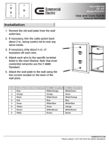
1. Run the A/V input cables (CAT 5/5e/6) from the PoleVault switcher along the raceway or behind
the wall to the desired junction box location.
N Two cables (A and B) are needed for the RGB signals, one for composite video.
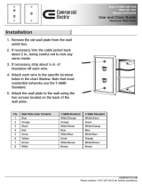
2. Thread the cables through the back of the junction box and out of the front.
3. Carefully cut off the terminating RJ-45 connector from each cable.
4. Strip the insulator of each cable wire back approximately 0.4" (1.1 cm).
5. Following the wiring diagram and table below, use a Tweeker to press down the spring switch,
and insert each wire into its correct location in the connector on the rear panel of the applicable
PVT. Release the spring to hold the wire securely in place.
PVT RGB CV MK and PVT RGB MK Installation Guide
The PVT RGB CV MK (2 -gang) and PVT RGB MK (1-gang) A/V wall plates for PoleVault
™
Systems can
be installed in MK junction boxes.
To install either of the devices,
Strip the insulator
0.4" (1.1 cm).
Press to hold the spring open.
Insert the wires according to
the table.
Release to close the spring.
Step 4
Step 5
1
2
3
4 5 6 7 8
5
Pin
1
Red +
2
Red –
3
H. sync +
Green –
6H. sync –
7
Blue +
8
Blue –
4
Wire Color
White-green
Green
White-orange
White-blue
Orange
White-brown
Brown
568A
Cable B
Green +
Blue
Cable A
V. sync +
V. sync –
+ 5 VDC
Audio L –
GND
Audio R +
Audio R –
Audio L +
Composite
Video Signals
Video +
Video –
+ 5 VDC
Audio L –
GND
Audio R +
Audio R –
Audio L +
RGB Signals
Top of
device
1
1&2
3&64&5
7&8
2345678
Cut off the
RJ-45 connector.
Twisted
Pairs
Step 3
Wire Color
568B
White-green
Green
White-orange
White-blue
Orange
White-brown
Brown
Blue
Cut below
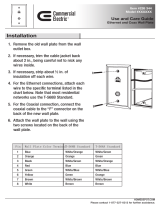
6. Where applicable, connect an IR cable from the MediaLink Controller to the rear IR connector
by inserting the signal wire into the hole marked “S”, and the ground wire into the
hole marked “G” (see inset, step 6).
7. Tighten down the screws.
8. Push all excess wiring into the box.
9. Using the supplied screws, attach the wall plate directly to the junction box.
10. Connect the applicable input device and, where applicable, an IR emitter to the PVT.
11. Power on the input device and the Polevault switcher.
N
The PVT wall plate is powered by the PoleVault switcher.
Refer to the “PoleVault System Installation Guide” to complete system installation and setup.
UTP Cable
Double Wide
Dry Lining Box
IR O
UT
S G
PVT
RGB
CV
MK
3.5 x 30 mm
Screw
Extron
PVT RGB CV MK
RGB and Composite
Line Driver
Extron Electronics, USA
800.633.9876 714.491.1500
FAX 714.491.1517
Extron Electronics, Europe
+800.3987.6673 +31.33.453.4040
FAX +31.33.453.4050
Extron Electronics, Asia
+800.7339.8766 +65.6383.4400
FAX +65.6383.4664
Extron Electronics, Japan
+81.3.3511.7655
FAX +81.3.3511.7656
www. extron.com
68-1526-01
Rev A
03 08
PVT RGB CV MK and PVT RGB MK Installation Guide, cont’d
Step 6
/