Atdec TH-3270-UFM Installation guide

Category
Flat panel wall mounts
Type
Installation guide

Atdec TH-3270-UFM is a full-motion flat-screen TV wall mount designed for displays ranging from 150 to 805mm wide and 140mm to 500mm high, with a maximum load capacity of 50kg. It features a sturdy construction and allows for smooth and easy adjustment of the TV's position, including tilt, swivel, and rotation, providing optimal viewing angles from different locations in the room. Cable management clips and covers are included to keep cables organized and concealed, ensuring a clean and clutter-free installation.

Atdec TH-3270-UFM is a full-motion flat-screen TV wall mount designed for displays ranging from 150 to 805mm wide and 140mm to 500mm high, with a maximum load capacity of 50kg. It features a sturdy construction and allows for smooth and easy adjustment of the TV's position, including tilt, swivel, and rotation, providing optimal viewing angles from different locations in the room. Cable management clips and covers are included to keep cables organized and concealed, ensuring a clean and clutter-free installation.

TM
TIGHTEN
FIRMLY
Flat Screen Wall Mount | Full Motion
Installation Instructions
Component Checklist
Hardware
IMPORTANT INFORMATION
! IMPORTANT - Install Telehook Wall Mount as per Installation Instructions.
! Telehook Wall Mount has a universal mounting hole pattern that suits a broad range of TVs:
from150 to 805mm wide (6” to 31¾”) and 140mm to 500mm high (5½” to 19¾”).
! Maximum Load: 50kg (110lbs)
! The Manufacturer accepts no responsibility for incorrect installation.
Step 1. Check Components
Check you have received all parts against the Component Checklist and Hardware above.
TH-3270-UFM
Step 2. Locate Drilling Position
WALL
Double-sided
tape (x2)
Drilling Guide
BACK
Un-fold the Drilling Guide and
open the Dust Collector.
Peel away the backing from the
double-sided adhesive tape.
Position the Drilling Guide vertically
onto the wall using a spirit level.
Choose the location of your Telehook Wall Mount, ensuring that the wall is structurally sound (for a timber stud
wall, locate the stud using a stud detection device). Use the Drilling Guide to mark out the hole centres.
Dust Collector
Drilling Guide
FRONT
Mounting Rail
Articulated Arm
Concrete
Anchor (x3)
5mm/6mm
Allen Key
M5 Washer
(x4)
M6 Washer
(x4)
M8x30mm / M8x50mm (x4 each)
M5x30mm / M5x45mm (x4 each)
M6x30mm / M6x45mm (x4 each)
M10 Coach
Screw (x3)
Mounting Screws
M4/5 Spacer
Bush (x4)
M6/8 Spacer
Bush (x4)
Drilling Guide
TOOLS REQUIRED:
• Power Drill
• Phillips Head Screwdriver
• Flat Blade Screwdriver
• Spirit Level
• 7mm (
9
/
32
”) Drill Bit
• 12mm (½”) Masonry Drill Bit
• 16mm (
5
/
8
”) Socket Wrench or Shifter
Step 8. Cable Management
Connect cables to your Display and
route through Cable Clips.
Step 9. Final Adjustment
Remove Cable Covers using a Phillips Head Screwdriver, and route
the cables along the length of the arms. Reattach the Cable Covers
to hold the Cables in place.
TIP: Leave slack in the
cables to allow full
movement at the joints.
Loosen screw with 5mm Allen key
and tilt the Display as desired.
Tighten screw with 5mm allen key
to lock the Display in desired position.
Tilt Down
Tilt Up
Top
M10 Washer
(x3)
M8 Washer
(x4)
Mounting
Bracket (x2)
Cable Covers
Cable Clip
Cables
TIP: The 5mm and 6mm
Allen Keys can be stored
in the Mounting Rail End
Caps.
End Cap
TIP: Use a Spirit Level to
check the Display is level.
Nylon
Washer
Mount Head
Screw
5mm Allen key
Step 7. Mounting the Display onto the Articulated Arm
( required)
Lower the Display so that the Hook
Plate locates with the Mounting
Head.
Mounting
Head
Hook
Plate
If necessary, adjust the horizontal
angle of the Mounting Rail so that
the Display is level.
Fix the Display in position using the
Mount Head Screw and Nylon
Washer supplied (see hardware).
Mount
Head Screw
+/-5°
Adjustment
5mm
Allen Key
Nylon
Washer
TIGHTEN
LOOSEN
No portion of this document or any artwork contained herein should be reproduced in any way without
the express written consent of Atdec Pty Ltd. Due to continuing product development, the manufacturer
reserves the right to alter specifications without notice. ©20200311A
Installation Complete
TIGHTEN
FIRMLY
ROTATE 90°
ROTATE
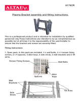
Step 3. Attaching the Articulated Arm to the Wall
Timber Stud Wall
- Using the Drilling Guide, drill three 7mm (
9
/
32
”)
diameter holes, 60mm (2
3
/
8
”) deep.
- Secure the Mouting Plate to the wall using the Coach
Screw and Washers supplied.
Masonry Wall
- Using the Drilling Guide, drill three 12mm (½”)
diameter holes, 60mm (2
3
/
8
”) deep.
- Secure the Mouting Plate to the wall using the Coach
Screw, Washers and Anchors supplied.
Remove the Telehook Arm from
the packaging and open fully.
Un-clip the Wall Plate
Cover and slide down the arm.
Wall Plate Cover
Coach Screw
M10 (x3)
Coach Bolt
M10 (x3)
Masonry
Wall
Timber
Stud
Concrete
Anchor (x3)
Step 4. Attaching the Mounting Brackets to your Display
Top of
Display
Back of Display
Choose appropriate Mounting Screws and Washers
from the Hardware supplied to suit your Display.
Mounting Screws (x4)
Washers (x4)
Mounting
Bracket
Recessed Mounting Holes or
Display with a Curved Rear Panel
Mounting
Screw
Spacer
Bush
Mounting
Hole
Washer
Step 6. Attaching the Mounting Rail to the Mounting Brackets
Slide the Mounting Rail under
both Mounting Brackets.
Centralise the Mounting Rail on
the Display, then reinstall the
Locking Plates to clamp the
Mounting Rail in position.
If the Mounting Holes are recessed
into the back of the Display, or the
Display has a curved rear panel, use
the appropriate Spacer Bushes
supplied to pack the Mounting Holes.
NOTE: Ensure the Mounting Bracket
is securely fixed to the Display.
Mounting
Hole
Coach Washer
M10 (x3)
Coach Washer
M10 (x3)
TIP: Secure the Mounting Bracket to the Display
through the top hole first, then the bottom slot.
Remove the Locking Plate from
each Mounting Bracket using the
5mm Allen Key supplied.
Locking
Plate
LOOSEN
5mm
Allen Key
Mounting
Bracket
CENTRE
Mounting
Rail
Mounting
Bracket
Locking
Plate
5mm
Allen Key
Mounting
Bracket
TIGHTEN
FIRMLY
Step 5. Landscape or Portrait Setup
NOTE: The Mounting Rail is factory set to mount the Display in a landscape position.
If you wish to mount the Display in a portrait position, please carry out the following instructions (if not, skip to Step 6).
Remove the:
• Cover Plate.
• Two Button Head Screws using the
5mm Allen Key supplied.
TIP: Use a small Flat Blade
Screwdriver to help prise the
Cover Plate loose.
LOOSEN
5mm
Allen Key
Cover
Plate
Loosen, but do not remove the
Centre Pin using the 6mm Allen Key
supplied.
Rotate the Hook Plate 90°,
then re-tighten the Centre Pin.
LOOSEN
TIGHTEN
Centre
Pin
Hook
Plate
6mm Allen Key
Remove the lower Cable Clip.
Then reinstall the two Button Head
Screws and Cover Plate.
PUSH
PUSH
Cable Clip
OR
  • Page 1 1
  • Page 2 2

Atdec TH-3270-UFM Installation guide

Category
Flat panel wall mounts
Type
Installation guide

Atdec TH-3270-UFM is a full-motion flat-screen TV wall mount designed for displays ranging from 150 to 805mm wide and 140mm to 500mm high, with a maximum load capacity of 50kg. It features a sturdy construction and allows for smooth and easy adjustment of the TV's position, including tilt, swivel, and rotation, providing optimal viewing angles from different locations in the room. Cable management clips and covers are included to keep cables organized and concealed, ensuring a clean and clutter-free installation.

Ask a question and I''ll find the answer in the document

Finding information in a document is now easier with AI