Page is loading ...

Catalog Number 61780-18
8362 sc High Purity Water Panel
USER MANUAL
May 2005 Edition 2
©Hach Company, 2005. All rights reserved. Printed in the U.S.A.
eac/kt

Visit http://www.hach.com

3
Table of Contents
Section 1 Specifications......................................................................................................................................... 5
Section 2 General Information............................................................................................................................... 7
2.1 Safety Information............................................................................................................................................... 7
2.2 Precautionary Labels .......................................................................................................................................... 7
2.3 General Product Overview.................................................................................................................................. 8
2.3.1 Measurement Principle.............................................................................................................................. 8
Section 3 Installation............................................................................................................................................ 11
3.1 Mounting the Panel ........................................................................................................................................... 11
3.2 Preparing for System Measurement ................................................................................................................. 12
3.3 Sample Connections......................................................................................................................................... 13
3.4 Flow Rate and Pressure.................................................................................................................................... 13
3.5 Connecting to the Controller ............................................................................................................................. 13
3.6 Wiring the Probe to the Junction Box................................................................................................................ 13
Section 4 sc100 Operation ................................................................................................................................... 17
4.1 Using the sc100 Controller................................................................................................................................ 17
4.1.1 sc100 Display Features ........................................................................................................................... 18
4.1.2 Important Key Presses ............................................................................................................................ 18
4.2 Sensor Setup .................................................................................................................................................... 19
4.2.1 Changing the Sensor Name.................................................................................................................... 19
4.3 Sensor Data Logging ........................................................................................................................................ 19
4.3.1 Sensor or Temperature Data Logging ..................................................................................................... 19
4.4 Sensor Diagnostics Menu................................................................................................................................. 20
4.5 pH Sensor Setup Menu..................................................................................................................................... 20
4.6 ORP Sensor Setup Menu.................................................................................................................................. 21
4.7 pH Calibration ................................................................................................................................................... 23
4.7.1 pH Calibration Procedure ........................................................................................................................ 23
4.7.2 Buffer Solutions (pH) ............................................................................................................................... 24
4.7.3 Two Point Automatic Calibration Method ................................................................................................. 25
4.7.4 One Point Automatic Calibration Method (optional)................................................................................. 26
4.7.5 Two Point Manual Calibration Method ..................................................................................................... 27
4.7.6 One Point Manual Calibration Method (optional)..................................................................................... 28
4.8 ORP Calibration................................................................................................................................................ 29
4.8.1 ORP Calibration Procedure..................................................................................................................... 29
4.8.2 One-point Manual Calibration.................................................................................................................. 30
4.9 Overflow Sample Method (ASTM Method) Procedure...................................................................................... 30
4.10 Concurrent Calibration of Two Sensors for pH and ORP................................................................................ 32
4.11 Adjusting the Temperature.............................................................................................................................. 32
4.11.1 Adjusting the Temperature Procedure................................................................................................... 32
Section 5 sc1000 Operation................................................................................................................................. 33
5.1 Using the sc1000 Controller.............................................................................................................................. 33
5.1.1 Display Features...................................................................................................................................... 33
5.1.1.1 Using the Pop-up Toolbar.............................................................................................................. 33
5.1.1.2 Using the Menu Windows .............................................................................................................. 33
5.1.1.3 Navigating the Menu Windows....................................................................................................... 34
5.2 Sensor Setup .................................................................................................................................................... 36
5.3 Sensor Data Logging ........................................................................................................................................ 37
5.4 Sensor Diagnostics Menu for pH and ORP....................................................................................................... 37
5.5 pH Sensor Setup Menu..................................................................................................................................... 37

4
Table of Contents
5.6 ORP Sensor Setup Menu..................................................................................................................................39
5.7 pH Calibration....................................................................................................................................................41
5.7.1 pH Calibration Procedure.........................................................................................................................41
5.7.1.1 Buffer Solutions (pH) ......................................................................................................................42
5.7.2 Two Point Automatic Calibration Method..................................................................................................43
5.7.3 One Point Automatic Calibration (optional) ..............................................................................................43
5.7.4 Two Point Manual Calibration Method......................................................................................................44
5.7.5 One Point Manual Calibration Method .....................................................................................................44
5.8 ORP Calibration.................................................................................................................................................45
5.8.1 ORP Calibration Procedure......................................................................................................................45
5.8.2 One-point Manual Calibration Method .....................................................................................................45
5.9 Overflow Sample Method (ASTM Method) Procedure ......................................................................................46
5.10 Concurrent Calibration of Two Sensors for pH and ORP.................................................................................48
5.11 Adjusting the Temperature...............................................................................................................................48
Section 6 Maintenance..........................................................................................................................................49
6.1 Cleaning the Instrument ....................................................................................................................................49
6.2 Sensor/Electrode Maintenance .........................................................................................................................49
Section 7 Troubleshooting....................................................................................................................................51
Section 8 Replacement Parts and Accessories..................................................................................................53
Section 9 How to Order.........................................................................................................................................55
Section 10 Repair Service.....................................................................................................................................56
Section 11 Limited Warranty ................................................................................................................................57

5
Section 1 Specifications
Specifications are subject to change without notice.
General
Components 316 SS back panel with pH or ORP sensor, flowmeter, and junction box
Measurement Range
(pH)
2 to 12 pH at 0 to 80 °C (32 to 176 °F)
Measurement Range
(ORP)
–1500 to +1500 mV at 0 to 50 °C (32 to 122 °F)
Temperature Range 0 to 80 °C (32 to 176 °F)
Accuracy < 0.1 pH or ± 5 mV for ultra pure water
Repeatability 0.01 pH/24 hours
Flow Rate 100 to 300 mL/min (100 to 300 cc/min)
Maximum Pressure 4 bar @ 25 °C (58 psi)
Temperature Probe Pt100
Dimensions 304.8 x 384.4 x 165.1 mm (12 x 15.13 x 6.5 in.)
Weight 3.6 kg (8 lb)
Cable Length 7.7 m (25 ft) supplied
Operating Conditions
Ambient Temperature 0 to 60 °C (32 to 140 °F)
Ambient Humidity 0 to 100% non-condensing

Visit us at www.hach.com

7
Section 2 General Information
2.1 Safety Information
Please read this entire manual before unpacking, setting up, or operating this equipment.
Pay attention to all danger and caution statements. Failure to do so could result in serious
injury to the operator or damage to the equipment.
To ensure that the protection provided by this equipment is not impaired, do not use or
install this equipment in any manner other than that specified in this manual.
Use of Hazard Information
DANGER
Indicates a potentially or imminently hazardous situation which, if not avoided,
could result in death or serious injury.
CAUTION
Indicates a potentially hazardous situation that may result in minor or moderate
injury.
Important Note: Information that requires special emphasis.
Note: Information that requires special emphasis.
2.2 Precautionary Labels
Read all labels and tags attached to the instrument. Personal injury or damage to the
instrument could occur if not observed
.
This symbol, if noted on the instrument, references the instruction manual for operation and/or safety information.
Electrical equipment marked with this symbol may not be disposed of in European public disposal systems after 12
August of 2005. In conformity with European local and national regulations (EU Directive 2002/96/EC), European
electrical equipment users must now return old or end-of life equipment to the Producer for disposal at no charge to
the user.
Note: For all electrical products (marked or unmarked) which are supplied or produced by Hach-Lange, please
contact the local Hach-Lange sales office for instructions for proper disposal.
This symbol, if noted on the product, indicates the need for protective eye wear.
This symbol, when noted on the product, identifies the location of the connection for Protective Earth (ground).

8
General Information
2.3 General Product Overview
DANGER
The 8362 sc High Purity Water pH or ORP sensor is not approved for hazardous
locations.
The 8362 sc High Purity Water pH/ORP panel is preplumbed and includes the 8362 sc
High Purity Water Sensor (Figure 1), digital electronics junction box, flow meter, and
mounting assembly. The 8362 sc High Purity Water pH/ORP Sensor contains two
electrodes; one for pH or ORP and the other for temperature.
The water runs through the 8362 sc High Purity Water Sensor then through a flow meter,
finally exiting the panel. The flow meter adjusts the sample stream from 0–300 mL/min
(0–300 cc/min.). The sensor then sends a mV signal and a temperature signal through
separate cords to a junction box which translates the analog pH/ORP and temperature
signal from the sensor into a digital signal to be read by the digital controller. Refer to
Specifications on page 5.
The 8362 sc High Purity Water panel is a manufactured panel to simplify and enhance the
connection between sensor and controller. It uses a self-pressurizing reference electrode
that introduces a constant flow of electrolyte into the sample stream. This constant flow of
electrolyte reduces the effects of electrolyte oscillations that cause reference junction
potential phase shifts that are found in other measuring systems. In addition, the
electrodes are housed in a special stainless steel housing and unique conductive flow
chamber to greatly reduce the effects of streaming currents that cause pH or ORP
measurements in high purity water to drift.
2.3.1 Measurement Principle
This 8362 sc High Purity Water pH/ORP system is specially designed for continuous
measurement of pure and ultra-pure water. It uses a reference electrode similar to the
measuring electrode to minimize the impedance of the measurement. The body is made
of 316 L stainless steel, which protects the measurements from electrostatic and magnetic
disturbances. The circulation chamber was designed without a retention zone to avoid
interference from CO
2
dissolution, air bubble accumulation, or insoluble deposits
accumulation (iron oxide, residues salted out by resins, etc.).

9
General Information
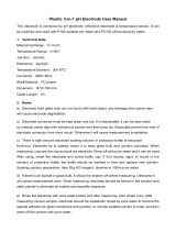
Figure 1 8362 Probe Components
1. pH or ORP cable assembly (Cat. No. 359016,10110) 9. Mounting bracket
2. pH (Cat. No. 08362=A=0000) electrode or
ORP (Cat. No. 08362=A=1111) electrode
10. M6 x 10 mm and M6 lock washer screw (2)
3. Electrode support 11. Temperature sensor (Cat. No. 08362=A=1001)
4. Earth ground connection 12. Temperature sensor retaining nut
5. Measurement chamber retaining nut 13. To digital electronics junction box
6. Protective cap 14. Temperature cable assembly
(Cat. No. 08362=A=3001)
7. Measurement chamber 15. To digital electronics junction box
8. Ground screw

Visit us at www.hach.com

11
Section 3 Installation
DANGER
Only qualified personnel should perform the installation tasks described in this
section of the manual.
The panel comes pre-assembled with all the components attached. See Section 5 on
page 15 for replacement parts and accessories.
After unpacking, it is recommended to save the shipping carton and packing materials in
case the instrument must be stored or reshipped. Inspect the equipment and packing
materials for signs of shipping damage. If there is any evidence of damage, notify the
transit carrier immediately.
3.1 Mounting the Panel
1. The panel is mounted to a wall or other hard and stable surface. Choose a convenient
location to read the flow meter and to run cables from the controller to the panel and
the junction box. Extension cables are available through Hach, refer to Replacement
Parts and Accessories on page 53.
2. Mount the panel by using the four holes at the corners of the panel. Be sure that the
panel is securely fastened to avoid injury to persons and equipment. Refer to Figure 2
for mounting dimensions.
3. Earth ground the panel to protect it from electrical noise by grounding to the panel or
bring ground to the ground screw on the flow chamber.
Note: The digital controller and panel need to be earth ground to the same source.

12
Installation
Figure 2 Panel Mounting Dimension
3.2 Preparing for System Measurement
1. Remove the measurement chamber (see Figure 1 on page 9).
2. Remove the protective cap covering the electrode bulb and rinse with demineralized
water or pH buffer for pH measurement or ORP standard solution for ORP
measurement. Save the protective cap if the electrode will be stored for long
periods of time.
3. Replace the measurement chamber.

13
Installation
3.3 Sample Connections
1. Connect the sample stream flow to the sample-in port.
2. Connect a drain tube to the sample-out port.
Note: It is not recommended to run the sample stream back into the main flow stream.
3. Introduce the sample and visually check the measurement chamber for bubbles that
could disturb the measurement.
4. Adjust the flow to between 100–300 mL/min (100–300 cc/min) for best results.
3.4 Flow Rate and Pressure
Observe the following for optimum operation:
• Keep the flow constant at a rate between 100–300 mL/min (100–300 cc/min) at a
maximum pressure of 4 bar (58 psi) for best operation.
• Keep the drain line as short as possible to avoid back-pressure.
• Earth ground the flow chamber to protect it from external electrical noise
(Figure 3).
• Do not allow the flow chamber to become empty. Keep the glass electrode bulb in
water to avoid electrode damage.
• Use the protective cap filled with KCl (3 M) on the pH or ORP electrode for storage
of up to one year. Never store your electrode in air even if it is in the flow chamber.
3.5 Connecting to the Controller
Connect the extension cable from the controller to the panel with the quick-connection
fitting on the side of the junction box (Figure 3). See the controller user manual for detailed
information on configuring and using the controller.
3.6 Wiring the Probe to the Junction Box
Refer to Figure 4 and Table 1 on page 15 when installing new cables from the pH/ORP
electrode or temperature sensor to the junction box.

14
Installation
Figure 3 Measurement System Electrical Connection to Digital Gateway

15
Installation
Figure 4 Junction Box Wiring
Table 1 Junction Box Wiring Information
pH/ORP Electrode Temperature Sensor
Black–Rigid (center) wire = measuring pH or ORP Brown and white wire = Pt100
Green–Copper internal shield = reference
Green–Copper external shield= connect to the ground plane of the
transmitter

Visit us at www.hach.com

17
Section 4 sc100 Operation
4.1 Using the sc100 Controller
The front of the controller is shown in Figure 5. The keypad consists of the eight keys
described in Table 2.
Figure 5 Front of the Controller
1. Instrument display 5. IrDA Port
2.
BACK key 6. HOME key
3.
MENU key 7. ENTER key
4.
RIGHT, LEFT, UP, and DOWN keys
Table 2 Controller Key Functions/Features
Number Key Function
2 Moves back one level in the menu structure.
3
Moves to the main menu from other menus. This key is not active in menus where a selection or
other input must be made.
4 Navigates through the menus, changes settings, and increments and decrements digits.
6
Moves to the Main Measurement screen from any other screen. This key is not active in menus
where a selection or other input must be made.
7 Accepts an input value, updates, or accepts displayed menu options.
sc100
1
2
6
5
3
7
4

18
sc100 Operation
4.1.1 sc100 Display Features
When a sensor is connected and the controller is in measurement mode, the controller
automatically identifies the connected sensors and displays associated measurements.
The display will flash on startup, when a sensor error has occurred, and when a sensor is
being calibrated.
An active system warning will cause the warning icon (a triangle with an exclamation point
inside) to be displayed on the right side of the display. See Figure 6.
Figure 6 Display
4.1.2 Important Key Presses
Note: The following are examples and may not represent exactly what is shown on the screen.
• Press HOME then the RIGHT or LEFT key to display two readings when two sensors
are connected. Continue to press the
RIGHT or LEFT key to toggle through the
available display options as shown below.
• Press the
UP and DOWN keys to toggle the status bar at the bottom of the
measurement display to display the secondary measurement (temperature) and
output information.
• When in Menu mode, an arrow may appear on the right side of the display to indicate
that more menus are available. Press the
UP or DOWN key (corresponding to the
arrow direction) to display additional menus.
1. Status bar. Indicates the sensor name and status of relays. The relay
letter is displayed when the relay is energized.
4. Parameter
2. Main measurement 5. Warning icon area
3. Secondary measurement (if applicable) 6. Measurement units
7.00
SENSOR NAME:
pH
TEMP: 23.0°C
1
2
3
6
5
4
pH pHpH
7.00
SENSOR NAME:
TEMP: 23.0°C
7.00
SENSOR NAME:
OUTPUT1: 12.00 mA
pH
7.00
SENSOR NAME:
OUTPUT2: 12.00 mV
pHpH
SENSOR DIAG
SENSOR SETUP
TEST/MAINT
MAIN MENU
SYSTEM SETUP
OUTPUT SETUP
SYSTEM SETUP
NETWORK SETUP
RELAY SETUP
DISPLAY SETUP
DISPLAY SETUP
SYSTEM SETUP
LOG SETUP
SECURITY SETUP
CALCULATION
SECURITY SETUP
SYSTEM SETUP
CALCULATION
LOG SETUP
ERROR HOLD MODE

19
sc100 Operation
4.2 Sensor Setup
When a sensor is initially installed, the serial number of the sensor will be displayed as the
sensor name. To change the sensor name refer to the following instructions:
4.3 Sensor Data Logging
The data logs store the measurement data at selected intervals. The event log stores a
variety of events that occur on the devices such as configuration changes, alarms, and
warning conditions. The data logs are stored in a packed binary format and the event logs
are stored in a CSV format. The logs can be downloaded through the digital network port,
service port, or the IrDA port. DataCom is needed for downloading logs to a computer.
4.2.1 Changing the Sensor Name
Step Select Menu Level/Instructions Confirm
1 MAIN MENU —
2 SENSOR SETUP
3 Highlight the appropriate sensor if more than one sensor is attached.
4 CONFIGURE
5 — EDIT NAME
6
Select the character to edit. —
Choose the appropriate digit.
4.3.1 Sensor or Temperature Data Logging
Step Select Menu Level/Instructions Confirm
1 MAIN MENU —
2 SENSOR SETUP
3 Highlight the appropriate sensor if more than one sensor is attached
4 CONFIGURE
5 LOG SETUP
6 Select SENSOR INTERVAL or TEMP INTERVAL
7 Choose from the displayed options.

20
sc100 Operation
4.4 Sensor Diagnostics Menu
SELECT SENSOR
ERROR LIST–See section 7.1 on page 45.
WARNING LIST–See section 7.2 on page 45.
4.5 pH Sensor Setup Menu
SELECT SENSOR (if more than one sensor is attached)
CALIBRATE
1 POINT AUTO
Calibration with a single buffer — normally pH 7.
2 POINT AUTO
Calibration with two buffers — normally pH 7 and pH 4 or 10.
1 POINT MANUAL
Calibration against a single known sample.
2 POINT MANUAL
Calibration against two samples, both with a known pH.
TEMP ADJUST
Adjust the displayed temperature by up to ± 15 °C.
DEFAULT SETUP
Restores the system to the original factory calibration.
CONFIGURE
EDIT NAME
Enter up to a 10-digit name in any combination of symbols and alpha or numeric characters.
SELECT MEASURE
Select the appropriate measurement units to display.
DISPLAY FORMAT
Select the measurement resolution (xx.xx pH or xx.x pH).
TEMP UNITS
Choose from the displayed options (°C or °F).
LOG SETUP
Choose SENSOR INTERVAL to set sensor log interval or select TEMP INTERVAL to set temperature log interval.
REJECT FREQ
Choose 50 or 60 Hz depending on the power line frequency for optimal noise rejection. Default is 60 Hz.
FILTER
Select 0–60 second signal averaging time.
TEMP ELEMENT
Select type of temperature element from the displayed choices.
SELECT BUFFER
Select the buffer type (standard 4, 7, 10 or DIN 19267) from the displayed choices.
PURE H20 COMP
Allows the user to specify that ammonia, morpholine, or other user-defined electrolyte is being used in the application,
allowing a temperature-dependent linear slope factor to be applied to the measured pH.
/