Page is loading ...

DOC023.97.80089
pHD Sensor
07/2016, Edition 3
User Manual
Manuel d'utilisation
Manual del usuario
Manual do Usuário
用户手册
取扱説明書
사용 설명서

English..............................................................................................................................3
Français......................................................................................................................... 20
Español.......................................................................................................................... 38
Português...................................................................................................................... 56
中文................................................................................................................................. 74
日本語............................................................................................................................. 91
한글............................................................................................................................... 109
2

Specifications
Specifications are subject to change without notice.
Specification Details
Measurement range (pH) 2.5 to 12.5 pH
Measurement range (temperature) -5 to 95 °C (23 to 203 °F)
Resolution 0.01 or 0.1 pH
Temperature compensation 300 ohm NTC thermistor
Stability (analyzer only) 0.03 pH per 24 hours, non-cumulative
Sensitivity Less than 0.005 pH
Maximum probe immersion depth/
pressure
6.9 bar at 105 °C (100 psi at 221 °F)
Maximum flow rate 3 m (10 ft) per second
Power requirements 5 VDC, 1 mA (supplied by controller)
Operating temperature -5 to 95 °C (23 to 203 °F)
Cable lengths/type 6 m (20 ft), 5 conductor (plus two isolated shields) cable with XLPE
(cross-linked polyethylene) jacket; rated to 150 °C (302 °F)
Maximum transmission distance 914 m (3000 ft)
Calibration methods Initial 2-point calibration using 2 buffers and then option to use 1-point or
2-point (slope) calibration using samples or buffers
Interfaces Modbus from gateway
Material Ryton
®
(PVDF) body, salt bridge of matching material with Kynar
®
junction, glass process electrode, titanium ground electrode, and Viton
®
O-ring seals
General Information
In no event will the manufacturer be liable for direct, indirect, special, incidental or consequential
damages resulting from any defect or omission in this manual. The manufacturer reserves the right to
make changes in this manual and the products it describes at any time, without notice or obligation.
Revised editions are found on the manufacturer’s website.
Safety information
Please read this entire manual before unpacking, setting up or operating this equipment. Pay
attention to all danger and caution statements. Failure to do so could result in serious injury to the
operator or damage to the equipment.
Make sure that the protection provided by this equipment is not impaired, do not use or install this
equipment in any manner other than that specified in this manual.
Use of hazard information
D A N G E R
Indicates a potentially or imminently hazardous situation which, if not avoided, will result in death or serious injury.
W A R N I N G
Indicates a potentially or imminently hazardous situation which, if not avoided, could result in death or serious
injury.
English 3

C A U T I O N
Indicates a potentially hazardous situation that may result in minor or moderate injury.
N O T I C E
Indicates a situation which, if not avoided, may cause damage to the instrument. Information that requires special
emphasis.
Precautionary labels
Read all labels and tags attached to the instrument. Personal injury or damage to the instrument
could occur if not observed. A symbol on the instrument is referenced in the manual with a
precautionary statement.
This is the safety alert symbol. Obey all safety messages that follow this symbol to avoid potential
injury. If on the instrument, refer to the instruction manual for operation or safety information.
This symbol indicates that a risk of electrical shock and/or electrocution exists.
This symbol indicates the presence of devices sensitive to Electro-static Discharge (ESD) and
indicates that care must be taken to prevent damage with the equipment.
Electrical equipment marked with this symbol may not be disposed of in European public disposal
systems after 12 August of 2005. In conformity with European local and national regulations (EU
Directive 2002/96/EC), European electrical equipment users must now return old or end-of-life
equipment to the Producer for disposal at no charge to the user.
Product overview
This sensor is designed to work with the digital gateway for the CLF10sc and CLT10sc Reagentless
Chlorine Analyzer and one of the sc series controllers for data collection and operation.
This sensor has an internal temperature sensor (thermistor). The temperature measurement signal is
used internally by the sensor for automatic temperature compensation and is shown on the
controller.
Theory of operation
pH is the negative logarithm of the hydrogen ion activity and a measure of the acidity or alkalinity of a
solution.
pH is normally measured with a glass electrode and a reference electrode. The glass electrode acts
as a transducer which converts chemical energy (the hydrogen ion activity) into an electrical energy
(measured in millivolts). The reaction is balanced and the electrical circuit is completed by the flow of
ions from the reference solution to the solution under test.
The electrode and reference solution together develop a voltage (emf) whose magnitude depends on
the type of reference electrode, the internal construction of the glass electrode, the pH of the solution
and the temperature of the solution.
Product components
Refer to Figure 1 to make sure that all components have been received. If any of these items are
missing or damaged, contact the manufacturer or a sales representative immediately.
4
English

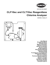
Figure 1 Sensor components
1 pHD sensor 2 Sealing hub for pH flow cell
Installation
C A U T I O N
Personal injury hazard. Only qualified personnel should conduct the tasks described in this section of the manual.
Install the sensor
The pH sensor must be installed in the flow cell, connected to the gateway and calibrated before use.
The sensor does not need to be conditioned. To install the sensor, refer to the illustrated steps.
English
5

1 2
3 4
6 English

Connect the sensor to the gateway
D A N G E R
Electrocution Hazard. High voltage wiring for the controller is conducted behind the high voltage barrier in the
controller enclosure. The barrier must remain in place except when installing modules, or when a qualified
installation technician is wiring for power, relays or analog and network cards.
W A R N I N G
Potential Electrocution Hazard. Always disconnect power to the instrument when making electrical
connections.
N O T I C E
Potential Instrument Damage. Delicate internal electronic components can be damaged by static
electricity, resulting in degraded performance or eventual failure.
Pre-requisites: Make sure the sensor cable is routed through the sealing hub and then the lock ring
for the pH flow cell before doing this procedure. Refer to Install the sensor on page 5 for the
illustrated steps.
To connect the sensor to the gateway, refer to the illustrated steps and Table 1.
Table 1 pHD sensor wire connections
Connector Pin Signal Sensor wire
J4 WHT -5 VDC White
SHLD Solution ground Clear (2 wires)
BLK Temp – Black
YEL Temp + Yellow
GRN (TB1) 1 Reference Green
2 Reference —
RED (TB2) 1 Active/Measuring —
2 Active/Measuring Red
English 7

1
2 3
8 English

4
5 6
English 9

Operation
Guidelines for operation
C A U T I O N
Personal injury hazard. If the pH process electrode breaks, handle the sensor very carefully to prevent injury.
• Before the pH sensor is placed in operation, remove the protective cap to expose the process
electrode and salt bridge. Save the protective cap for future use.
• The process electrode at the pH sensor tip has a glass bulb, which can break. Do not subject this
electrode to abrupt impact or other mechanical abuse.
• For short-term storage (when the sensor is out of the process for more than one hour), fill the
protective cap with pH 4 buffer or distilled water and put the cap back on the sensor. Keep the
process electrode and salt bridge moist to avoid slow response when the sensor is returned to
operation.
• For extended storage, repeat the short-term storage procedure every 2 to 4 weeks, depending on
the environmental conditions.
User navigation
Refer to the controller documentation for keypad description and navigation information.
Configure the sensor
Use the Configure menu to enter identification information and display options for the sensor and to
change options for data handling and storage.
1. Push the MENU key and select Sensor Setup, Configure.
Option Description
EDIT NAME Changes the name that corresponds to the sensor on the top of the measure screen.
The name is limited to 10 characters in any combination of letters, numbers, spaces or
punctuation. The default name is the serial number of the sensor.
SELECT PARAM. Customizes the options for sensor data handling and storage. Refer to Select
temperature parameters on page 10 and Select pH parameters on page 11.
RESET DEFAULTS Sets the configuration menu to the default settings. All sensor information is lost.
Select temperature parameters
1. Select the type of chlorine sensor used - Total CL2 or Free CL2.
2. Select Yes.
3. Select DIFF PH.
4. Select Temperature.
5. Customize the options:
Option Description
SELECT UNITS Sets the units for the temperature measurements-°C (default) or °F.
FILTER Sets a time constant to increase signal stability. The time constant calculates the average
value during a specified time-0 (no effect, default) to 60 seconds (average of signal value
for 60 seconds). The filter increases the time for the sensor signal to respond to actual
changes in the process.
LOG SETUP Sets the time interval for data storage in the data log-10, 30 seconds, 1, 5, 15 (default),
60 minutes.
10 English

Select pH parameters
1. Select the type of chlorine sensor used - Total CL2 or Free CL2.
2. Select Yes.
3. Select DIFF PH.
4. Select pH.
5. Customize the options:
Option Description
DISPLAY
FORMAT
Sets the number of decimal places that are shown on the measure screen-XX.XX or
XX.X
FILTER Sets a time constant to increase signal stability. The time constant calculates the
average value during a specified time-0 (no effect, default) to 60 seconds (average of
signal value for 60 seconds). The filter increases the time for the sensor signal to
respond to actual changes in the process.
LOG SETUP Sets the time interval for data logging-10, 30 seconds, 1,5, 15 (default), 60 minutes.
Calibrate the sensor
About sensor calibration
The sensor characteristics slowly shift over time and cause the sensor to lose accuracy. The sensor
must be calibrated regularly to maintain accuracy. The calibration frequency varies with the
application and is best determined by experience.
Recalibrate the sensor whenever disconnected from power and removed from water.
Temperature calibration procedure
One measurement is required for temperature calibration of this sensor. The measurement is made
with the pH sensor in a beaker that contains a sample or reference solution or with the pH sensor
installed in the flow cell.
1. To calibrate the temperature with the pH sensor in a beaker:
a. Put the sensor in the sample or reference solution.
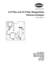
b. Make sure that the sensor is at least half immersed in the liquid (Figure 2 on page 12).
c. Stir the sensor to remove bubbles.
d. Wait for the sensor and solution temperature to equalize. This can take 30 minutes or more.
2. To calibrate the temperature with the pH sensor in the flow cell, install the pH sensor in the flow
cell and turn on the flow. Wait at least 30 minutes after flow is started for the temperature
readings of the pH sensor to stabilize.
3. Push the MENU key and select Sensor Setup, Calibrate, Temperature, Temp Cal.
4. If the passcode is enabled in the security menu for the controller, enter the passcode.
The controller shows "Stabilizing" until the temperature measurement stabilizes and then shows a
temperature measurement.
5. Select the option for the output signal during calibration:
Option Description
ACTIVE The instrument sends the current measured output value during the calibration procedure.
HOLD The sensor output value is held at the current measured value during the calibration procedure.
TRANSFER A preset output value is sent during calibration. Refer to the controller user manual to change
the preset value.
6. Measure the temperature of the sample or reference solution with a secondary verification
instrument (such as an NIST traceable thermometer).
7. Use the arrow keys to enter the measured value and push ENTER.
English
11

8. Review the calibration result:
• Passed—the sensor is calibrated and ready to measure samples. The offset value is shown.
• Failed—the calibration offset is outside of accepted limits. Refer to Troubleshooting
on page 16 for more information.
9. If the calibration passed, push ENTER to continue.
10. If the option for operator ID is set to Yes in the Calibration Options menu, enter an operator ID.
Refer to Change the calibration options on page 14.
11. On the New Sensor screen, select whether the sensor is new:
Option Description
YES The sensor was not calibrated previously with this instrument. The days of operation and previous
calibration curves for the sensor are reset.
NO The sensor was calibrated previously with this instrument.
12. Return the sensor to the process and push ENTER.
The output signal returns to the active state and the measured sample value is shown on the
measure screen.
Note: If the output mode is set to hold or transfer, select the delay time when the outputs return to the active
state.
pH calibration procedure
Pre-requisites: Do a temperature calibration before doing a pH calibration. The accuracy of the pH
measurement depends on the accuracy of the temperature measurement.
One or two measurements are required for pH calibration of this sensor. Measurements are made
with the pH sensor in a beaker that contains a sample or reference solution or with the pH sensor
installed in the flow cell.
Note: The pH sensor should first be calibrated with a reference solution(s) in a beaker. Then the pH sensor can be
calibrated with a sample(s) in a beaker or in the flow cell.
The pH can be calibrated with 1 or 2 reference solutions or samples (1-point or 2-point calibration).
Calibration adjusts the sensor reading to match the value of a reference solution(s) or sample(s).
A calibration is done by putting the pH sensor in a reference solution or sample with a known pH
value and then entering that known value into the controller. A buffer calibration identifies the buffer
table corresponding to the chosen buffer and automatically calibrates the probe after it stabilizes.
1. To calibrate the pH sensor in a beaker:
a. Put the sensor in the reference solution or sample.
b. Make sure that the sensor is at least half immersed in the liquid (Figure 2).
c. Stir the sensor to remove bubbles.
d. Wait for the sensor and solution temperature to equalize. This can take up to 30 minutes.
Figure 2 Sensor in reference solution or sample
2. To calibrate the pH sensor in the flow cell, install the pH sensor in the flow cell and turn on the
flow.
12
English

3. Push the MENU key and select Sensor Setup, Calibrate, pH.
4. Select the type of calibration:
Option Description
2 POINT
BUFFER
Use 2 buffers for calibration, for example pH 7 and pH 4 (recommended method). The
buffers must be from the buffer set that is specified in the Cal Options menu (refer to
Change the calibration options on page 14).
1 POINT
BUFFER
Use 1 buffer for calibration, for example pH 7. The buffer must be from the buffer set that
is specified in the Cal Options menu (refer to Change the calibration options
on page 14).
2 POINT
SAMPLE
Use 2 samples of known pH value for calibration. Determine the pH value of samples with
a different instrument.
1 POINT
SAMPLE
Use 1 sample of known pH value for calibration. Determine the pH value of sample with a
different instrument.
5. If the passcode is enabled in the security menu for the controller, enter the passcode.
6. Select the option for the output signal during calibration:
Option Description
ACTIVE The instrument sends the current measured output value during the calibration procedure.
HOLD The sensor output value is held at the current measured value during the calibration procedure.
TRANSFER A preset output value is sent during calibration. Refer to the controller user manual to change
the preset value.
7. With the sensor in the first reference solution or sample, push ENTER.
The measured pH and temperature value is shown.
8. Wait for the value to stabilize and push ENTER
1
.
9. If using a sample, measure the pH value with a secondary verification instrument. Use the arrow
keys to enter the measured value and push ENTER.
Note: If a pH buffer not listed in the Cal Options menu is used, refer to the buffer bottle to find the pH value that
corresponds to the temperature of the buffer.
10. For a 2-point calibration:
a. If using a reference solution, remove the sensor from the first solution and rinse with clean
water.
b. Put the sensor in the next reference solution or sample and push ENTER.
The measured pH and temperature value is shown.
c. Wait for the value to stabilize. Push ENTER
1
.
d. If the solution is a sample, measure the pH value with a secondary verification instrument.
Use the arrow keys to enter the measured value and push ENTER.
Note: If a pH buffer not listed in the Cal Options menu is used, refer to the buffer bottle to find the pH value
that corresponds to the temperature of the buffer.
11. Review the calibration result:
• Passed—the sensor is calibrated and ready to measure samples. The slope and/or offset
values are shown.
• Failed—the calibration slope or offset is outside of accepted limits. Repeat the calibration with
fresh reference or sample solution. Refer to Troubleshooting on page 16 for more
information.
12. If the calibration passed, push ENTER to continue.
1
If the option for Auto Stab (auto stabilization) is set to Yes in the Calibration Options menu, the
screen will advance to the next step automatically. Refer to Change the calibration options
on page 14.
English 13

13. If the option for operator ID is set to Yes in the Calibration Options menu, enter an operator ID.
Refer to Change the calibration options on page 14.
14. On the New Sensor screen, select whether the sensor is new:
Option Description
YES The sensor was not calibrated previously with this instrument. The days of operation and previous
calibration curves for the sensor are reset.
NO The sensor was calibrated previously with this instrument.
15. Return the sensor to the process and push ENTER.
The output signal returns to the active state and the measured sample value is shown on the
measure screen.
Note: If the output mode is set to hold or transfer, select the delay time when the outputs return to the active
state.
Reset calibration to defaults
To remove a bad calibration, replace the user calibration settings with the default calibration settings
using the Calibrate menu. Then recalibrate the sensor when needed.
1. Push the MENU key and select Sensor Setup, Calibrate, [Select Sensor], Reset Defaults.
2. If the passcode is enabled in the security menu for the controller, enter the passcode.
3. Select Yes and push Enter.
Change the calibration options
The user can select buffer solutions for pH calibrations, set a calibration reminder, enable auto
stabilization during calibrations or include an operator ID with calibration data from the Cal Options
menu.
1. Push the MENU key and select Sensor Setup, Calibrate, [Select Sensor], Cal Options.
2. Customize the options:
Option Description
SELECT BUFFER For pH only-changes the set of buffer solutions that are recognized for calibration to pH
4.00, 7.00, 10.00 (default set) or DIN 19267 (pH 1.09, 4.65, 6.79, 9.23, 12.75)
Note: Other buffers can be used if the 1 point sample or 2 point sample option is
selected during calibration.
AUTO STAB For pH only-enables the system to accept measurement signal values during calibrations
and advance to the next step of the calibration when the system determines the
measurement signal has stabilized-On or Off (default). Enter a stabilization range-0.01 to
0.1 pH unit.
CAL REMINDER Sets a reminder for the next calibration in days, months or years.
OP ID ON CAL Includes an operator ID with calibration data—Yes or No (default). The ID is entered
during the calibration.
Data log
The controller provides one data log for each sensor. The data log stores the measurement data at
selected intervals (user configurable). The data log can be read out in a CSV format. For instructions
on downloading the logs, please refer to the controller user manual.
Refer to Select temperature parameters on page 10 and Select pH parameters on page 11 for
information about setting time intervals for data storage in the data log.
Modbus registers
A list of Modbus registers is available for network communication. Refer to the CD for more
information.
14
English

Maintenance
C A U T I O N
Personal injury hazard. Only qualified personnel should conduct the tasks described in this section of the manual.
Maintenance schedule
Maintenance task Frequency
Clean and inspect the sensor 90 days
(The pH sensor may need to be cleaned more often
depending on water quality.)
Replace the standard cell solution and salt bridge 3 to 6 months
Replace the sensor 4-5 years
Clean the sensor
W A R N I N G
Chemical hazard. Always wear personal safety protection in accordance with the Material Safety Data Sheet for
the chemical that is used.
Examine the sensor periodically for debris and deposits. Clean the sensor when there is a buildup of
deposits or when performance has degraded.
Pre-requisites: Prepare a mild soap solution with a non-abrasive dishwashing detergent that does
not contain lanolin. Lanolin leaves a film on the electrode surface that can degrade the sensor
performance.
1. Turn off the flow.
2. Loosen the lock ring and remove the pH sensor from the flow cell.
3. Rinse the sensor with a stream of clean, warm water. If debris remains, carefully wipe the entire
measuring end of the sensor with a clean, soft cloth to remove the loose contaminate buildup.
Then rinse with clean water.
4. Soak the sensor for 2 to 3 minutes in the soap solution.
5. Use a soft bristle brush and scrub the entire measuring end of the sensor, thoroughly cleaning the
electrode and salt bridge surfaces.
6. If surface deposits remain, soak the measuring end of the sensor in dilute acid, such as muriatic
acid (or other dilute acid), for a maximum of 5 minutes.
Note: The acid should be as dilute as possible, not stronger than 3% HCL. Experience will determine which
acid to use and the appropriate dilution ratio. Some stubborn coatings may require a different cleaning agent.
Contact technical support.
7. Rinse the sensor with water and return to the soap solution for 2 to 3 minutes to neutralize any
remaining acid.
8. Rinse the sensor with clean water.
9. Calibrate the sensor in a beaker using a reference solution(s).
10. Install the pH sensor in the flow cell and tighten the lock ring.
English
15

Troubleshooting
Test the sensor
Pre-requisites: Two pH buffers (pH 7 and pH 4 or pH 10) and a multimeter.
Note: If a calibration fails, clean the sensor and replace the salt bridge and standard cell solution, and then repeat
the calibration. Only test the sensor if the problem is not corrected by maintenance.
1. Put the sensor in a pH 7 buffer solution and wait for the temperature of the sensor and buffer to
reach room temperature.
2. Disconnect the yellow and black sensor wires from the gateway.
3. Measure the resistance between the yellow and black wires to verify the operation of the
temperature element. The resistance should be between 250 and 350 ohms at approximately
25 ºC.
If the temperature element is good, reconnect the wires to the gateway.
4. Push the MENU key and select Sensor Setup, Diag/Test, Signals. The pH reading should be
between –50 and + 50 mV.
5. Rinse the sensor with water and put in a pH 4 or pH 10 buffer solution. Wait for the temperature
of the sensor and buffer to reach room temperature.
6. Compare the mV reading in the pH 4 or 10 buffer to the reading in the pH 7 buffer. The reading
should differ by approximately 160 mV.
If the difference is less than 160 mV, call technical support.
Diagnostic and test menu
The diagnostic and test menu shows current and historical information about the chlorine analyzer.
Refer to Table 2. To access the diagnostic and test menu, push the MENU key and select Sensor
Setup, Diag/Test.
Table 2 DIAG/TEST menu
Option Description
GATEWAY INFO Shows the firmware version, driver version, serial number and boot version for the
controller and the types of sensors connected to the controller.
CAL DAYS Shows the number of days since the sensor was last calibrated.
CAL HISTORY Shows a list of the times when the sensor was calibrated. Push ENTER to scroll
through the entries and view a summary of the calibration data.
RST CAL HISTORY Resets the sensor calibration history. Requires passcode.
SIGNALS Shows the sensor measurement signal value in mV.
SENSOR DAYS Shows the number of days the sensor has been in operation.
RST SENSORS Resets the sensor days and calibration days to default. Requires passcode.
CALIBRATION Shows the slope and offset values for chlorine and pH. Shows the offset value for
the temperature.
16 English

Error list
Errors may occur for various reasons. The sensor reading on the measurement screen flashes. All
outputs are held when specified in the controller menu. To show the sensor errors, push the MENU
key and select Sensor Diag, Error List. A list of possible errors is shown.
Table 3 Error list for the sensor
Error Description Resolution
CL CAL REQD A chlorine calibration and/or pH calibration is
required
The chlorine and/or pH measurement has
changed enough to cause a Cal Watch alarm
to occur. Refer to the chlorine sensor manual
for information on Cal Watch alarms.
Calibrate the chlorine sensor and/or pH
sensor.
PH TOO LOW The pH value is less than 0 pH Calibrate or replace the pH sensor.
PH TOO HIGH The pH value is more than 14 pH
PH SLOPE FAIL The slope is outside of the -45 to -65 mV/pH
range
Clean the pH sensor, then repeat the
calibration with a fresh buffer or sample, or
replace the sensor.
PH OFFSET FAIL The offset is outside of ±60 mV Clean the pH sensor and replace the salt
bridge and standard cell solution and then
repeat the calibration with a fresh buffer or
sample, or replace the sensor.
TEMP TOO LOW The temperature is less than 0 °C Calibrate the temperature or replace the pH
sensor.
TEMP TOO HIGH The temperature is more than 100 °C
TEMP FAIL The offset is higher than 5.0 °C or lower than
-5.0 °C
Calibrate the temperature or replace the pH
sensor.
Warning list
A warning does not affect the operation of menus, relays and outputs. A warning icon flashes and a
message is shown on the bottom of the measurement screen. To show the sensor warnings, push
the MENU key and select Sensor Diag, Warning List. A list of possible warnings is shown in Table 4.
Table 4 Warning list for the sensor
Warning Description Resolution
CL CAL RECD A chlorine and/or pH calibration is recommended
The chlorine and/or pH measurement has changed
enough to cause a Cal Watch warning alarm to occur.
Refer to the chlorine sensor manual for information on
Cal Watch alarms.
Calibrate the chlorine sensor
and/or pH sensor.
PH CAL RECD A pH calibration is recommended
pH calibration data is not available (sensor with default
calibration data)
Calibrate the pH sensor.
TEMP CAL RECD A temperature calibration is recommended
Temperature calibration data is not available (sensor
with default calibration data)
Calibrate the temperature.
PH CAL TO DO The Sensor Days value for the pH sensor is greater
than the Cal Reminder value
Calibrate the pH sensor.
TEMP CAL TO DO The Sensor Days value for the temperature sensor is
greater than the Cal Reminder value
Calibrate the temperature.
English 17

Table 4 Warning list for the sensor (continued)
Warning Description Resolution
PH MAINT RECD pH sensor maintenance is recommended
The slope is outside of the -50 to -61 mV/pH range
Clean the pH sensor, then repeat
the calibration with a fresh buffer
or sample, or replace the sensor.
PH MAINT RECD pH sensor maintenance is recommended
The offset is outside of ±45 mV but within ±60 mV
Clean the sensor and replace the
salt bridge and standard cell
solution and then repeat the
calibration, or replace the sensor.
T MAINT RECD The temperature offset is outside of ±3 °C but within
±5 °C
Calibrate the temperature.
Event log
The controller provides one event log for each sensor. The event log stores a variety of events that
occur on the devices such as calibrations done, calibration options changed, etc. A list of possible
events is shown in Table 5. The event log can be read out in a CSV format. For instructions on
downloading the logs, refer to the controller user manual.
Table 5 Event log
Event Description
Power On The power was turned on
Flash Failure The external flash has failed or is corrupted
1pointpHCalibration_Start Start of one-point sample calibration for pH
1pointpHCalibration_End End of one-point sample calibration for pH
2pointpHCalibration_Start Start of two-point sample calibration for pH
2pointpHCalibration_End End of two-point sample calibration for pH
1pointBufferpHCalibration_Start Start of one-point buffer calibration for pH
1pointBufferpHCalibration_End End of one-point buffer calibration for pH
2pointBufferpHCalibration_Start Start of two-point buffer calibration for pH
2pointBufferpHCalibration_End End of two-point buffer calibration for pH
TempCalibration_Start Start of temperature calibration
TempCalibration_End End of temperature calibration
pHCalSetDefault The pH calibration data was reset to the default
TempCalSetDefault The temperature calibration data was reset to the default
AllCalSetDefault All sensor calibration data was reset to the default
pHCalOptionChanged The pH calibration option was changed
TempCalOptionChanged The temperature calibration option was changed
SensorConfChanged The sensor configuration was changed
ResetpH CalHist The pH calibration history was reset
ResetTemp CalHist The temperature calibration history was reset
ResetAllSensorsCalHist All sensor calibration history was reset
ResetpHSensor The pH calibration data (sensor days, calibration history and calibration data)
was reset to the default
18 English

Table 5 Event log (continued)
Event Description
ResetTempSensor The temperature calibration data (sensor days, calibration history and
calibration data) was reset to the default
ResetAllSensors All sensor calibration data (sensor days, calibration history and calibration data)
was reset to the default
Replacement parts
Note: Product and Article numbers may vary for some selling regions. Contact the appropriate distributor or refer to
the company website for contact information.
Table 6
Description Quantity Item no.
Sensor, pHD
2
1 9181500
Sensor, protective cap for pH
3
1 1000F3374-001
Standard cell solution 500 mL 25M1A1025-115
Gel powder (mixed with the standard cell solution for high temperature
applications)
2 grams 25M8A1002-101
Salt bridge (includes O-ring) 1 SB-R1SV
Buffer solution, pH 4 500 mL 2283449
Buffer solution, pH 7 500 mL 2283549
Buffer solution, pH 10 500 mL 2283649
2
Includes sealing hub for the pH flow cell.
3
Includes sponge to keep pH glass bulb wet during storage.
English 19

Caractéristiques techniques
Les caractéristiques techniques peuvent être modifiées sans préavis.
Caractéristiques Détails
Plage de mesure (pH) pH 2,5 à 12,5
Plage de mesure (température) -5 à 95 °C (23 à 203 °F)
Résolution 0,01 ou 0,1 pH
Compensation en température Thermistance NTC 300 ohm
Stabilité (chloromètre uniquement) 0,03 pH toutes les 24 heures, non cumulée
Sensibilité Inférieure à 0,005 pH
Pression et profondeur d'immersion
maximales de la sonde
6,9 bars à 105 °C (100 psi à 221 °F)
Débit maximal 3 m (10 pi) par seconde
Alimentation électrique 5 Vcc, 1 mA maximum (fournie par le transmetteur)
Températures de fonctionnement -5 à 95 °C (23 à 203 °F)
Longueur et type de câble 6 m (20 pieds), câble à 5 conducteurs (plus deux blindages isolés)
avec prise XLPE (polyéthylène réticulé) ; testé jusqu'à 150 °C
(302 °F)
Portée de transmission maximale 914 m (3 000 pieds)
Méthodes de calibrage Etalonnage initial en 2 points à l'aide de 2 tampons, puis possibilité
d'utiliser l'étalonnage en 1 point ou en 2 points (pente) à l'aide
d'échantillons ou de tampons
Interfaces Modbus de la passerelle
Matériaux Structure Ryton
®
(PVDF), pont salin dans le même matériau que la
jonction Kynar
®
, électrode de processus en verre, électrode de
référence en titane et joints toriques Viton
®
Généralités
En aucun cas le constructeur ne saurait être responsable des dommages directs, indirects, spéciaux,
accessoires ou consécutifs résultant d'un défaut ou d'une omission dans ce manuel. Le constructeur
se réserve le droit d'apporter des modifications à ce manuel et aux produits décrits à tout moment,
sans avertissement ni obligation. Les éditions révisées se trouvent sur le site Internet du fabricant.
Consignes de sécurité
Veuillez lire l'ensemble du manuel avant le déballage, la configuration ou la mise en fonctionnement
de cet appareil. Respectez toutes les déclarations de prudence et d'attention. Le non-respect de
cette procédure peut conduire à des blessures graves de l'opérateur ou à des dégâts sur le matériel.
Assurez-vous que la protection fournie avec cet appareil ne soit pas compromise, n'utilisez pas ou
n'installez pas cet appareil d'une autre façon que celle décrite dans ce manuel.
Interprétation des indications de risques
D A N G E R
Indique une situation de danger potentiel ou imminent qui, si elle n'est pas évitée, peut entraîner la mort ou des
blessures graves.
20 Français
/