Page is loading ...

Installation Manual

2 of 11Surface 40/80 Speakers | 009-1656-01 | 180731
Copyright 2018 Savant Systems, LLC
45 Perseverance Way, Hyannis, MA 02601
Savant.com | 508.683.2500
Specifications Pre Construction Bracket Install
BOX CONTENTS
ADDITIONAL ACCESSORIES
Environmental
Temperature 5° to 122° F (-15° to 50° C)
Humidity 10% to 90% Relative Humidity (non-condensing)
Recommended Power
Surface 40 40 watts maximum
(overload protection built-in)
Surface 80 80 watts maximum
Dimensions and Weights
Height 23.0 in (58.42 cm)
Width 9.75 in (24.77 cm)
Depth
(Speaker) 3.125 in (7.94 cm)
(Mounting Cavity) 3.125 (7.94 cm)
Weight
Speaker: 7.2 lb (3.27 kg)
Shipping 11.0 lb (5.00 kg)
Nominal Impedance
8 Ohms
Cabinet / Finish
Acoustically tuned engineered aluminum enclosure. Aluminum honeycomb core, doped paper skin,
composite acoustic panel.
Regulatory
RoHS Compliant
Dispersion Angle
180° x 180° (H x V) Full Spectrum within 2dB
Sensitivity
86 dB @ 1 meter/1W with .079 in (2 mm) plaster skim coat
(1) Sound Surface 40 or Sound Surface 80 Invisible Speaker (SURFACE-40-00, SURFACE-80-00)
(6) M5 x 45 mm flathead screws (075-0216-xx)
(1) Sound Surface Spacer Kit (015-0229-xx) - (6 spacers of various widths)
(1) Surface Speaker 40 and 80 Cut-Out Template (009-0585-xx)
(1) Installation Handle (169-0202-00)
(1) Product Documentation Notice Insert (009-1683-00)
– Sound Surface Pre-Construction Bracket (SURFACE-1PCB-xx)
– Installation Handle (SURFACE-1IH-xx)
Frequency Response
80 Hz - 20 kHz +/- 2 db

3 of 11Surface 40/80 Speakers | 009-1656-01 | 180731
Copyright 2018 Savant Systems, LLC
45 Perseverance Way, Hyannis, MA 02601
Savant.com | 508.683.2500
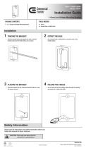
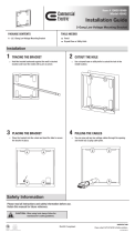
Pre Construction Bracket Install
– The pre-construction bracket is installed onto existing studs and will reserve an opening during the
rough stage so the drywall can be installed around it.
– Pre-construction brackets (sold separately) are available for stud and joist openings that are either 12
or 16 inch on center.
– With the use of the Pre-construction bracket, a smaller cavity can be used. The clearances required
for this installation are: (9
/4 in x 23 /2 in x 3 /8 in) (248 mm x 597 mm x 80 mm) deep.
– The pre-construction bracket can be used for installations that include either inch or ⅝ inch
drywall. With rubber spacers installed, ⅝ inch drywall can be used. With spacers removed, ½ inch
drywall can be used.
Figure 1.
1) Pre-Construction Bracket Installation
A Sound Surface Pre-construction bracket (SURFACE-1PCB-00) is available for installs where the wall
board is not installed.
Follow instructions below to install Pre-construction bracket:
1. When ½ inch drywall is being installed, remove the
rubber spacers from the rear of the bracket.
When ⅝ inch wall board is being installed, leave the
rubber spacers intact.
HELPFUL! The face of the bracket should be slightly
inset from the edge of the drywall. This allows for
joint compound to be spread over bracket to cre-
ate a level surface.
2. Attach the bracket to the wall studs or ceiling
joists using the (5) pre-drilled countersunk holes
positioned along the outside edge of the bracket.
See Figure 1.
TIP! Use mounting screws (not provided) appropriate
for the stud or joist type: wood, metal, etc.
3. After bracket is installed, proceed to section 4 -
Attach Handle. Skip the retrofit instructions on page
4 if this is new construction.
– For NEW CONSTRUCTION, follow the steps in section 1 - Pre Construction Bracket Installation. After pre-
construction bracket is installed, skip to section 4 Attach Handle
– For RETROFIT INSTALLATIONS, skip section 1 and start with section 2 - Mark the Wall/Ceiling
The Artison Sound Surface 40 and Sound Surface 80 speakers are designed to be installed into a wall
or ceiling. Once installed, the face of the speaker is then sheetrock mudded so the complete speaker is
embedded into the wall and can't be seen. Installation of the speaker varies slightly depending on whether
the install is done during initial construction or retrofitted after the drywall is already hung. Both installations
are described below:

4 of 11Surface 40/80 Speakers | 009-1656-01 | 180731
Copyright 2018 Savant Systems, LLC
45 Perseverance Way, Hyannis, MA 02601
Savant.com | 508.683.2500
2) Mark the Wall/Ceiling
3) Cut the Drywall
1. Use a stud locator instrument or other approach to mark the location of studs and other items that
may obstruct the installation of the speaker. See Figure 2 below.
2. The following clearances are required to install the speaker (with no obstruction from studs or other
wall fixtures): (9
/4 in x 26 /2 in x 3 /8 in) (248 mm x 675 mm x 80 mm). See Figure 3 below.
1. Place the Drywall Scoring Template onto the wall or ceiling where the speaker will be installed. As
described in step 2 above, ensure no studs or other obstructions are directly behind the wall where
the cuts will be made (Figure 3 above shows the clearances required).
2. Trace a thin line along the two longest sides of the template. The template incorporates a pencil
illustration
where the lines need to be made. See Figure 4 below.
3. Trace a thin line along the two slits at the top and bottom of template. These slits are also referenced
with a pencil illustration .
IMPORTANT! Do not mark a line along the top and bottom edges of the template. The cut line should be
made using the slits at the top and bottom of template.
4. Mark the six speaker mounting holes located at the top and bottom of template.
5. Remove template.
6. With a utility knife and straight edge ruler, score lines made in steps 2 and 3 above. Use care to cut
through the PAPER LAYER only.
7. With a drywall saw, cut the drywall on the INSIDE of the utility knife cut made in step 6 above. This
ensures the clean, sharp edge of the cut made with the utility knife is maintained. See Figure 5 below.
8. Insert the face of the speaker into the hole cut in step 7 above (dry fit). There should be about .079 in
(2 mm) of clearance around the perimeter of the speaker. Set speaker aside.
9. Drill a
/16 inch hole for each speaker mounting hole made in step 4 above.
Figure 2.
Figure 5.Figure 4.
26 ½ in
Clearances required
from obstructions
in wall
3 ⅛ in
9 ¾ in
Speaker
Figure 3.
Installation - Retrofit
Cut INSIDE the
utility knife cut
line with drywall saw
Pencil Line

5 of 11Surface 40/80 Speakers | 009-1656-01 | 180731
Copyright 2018 Savant Systems, LLC
45 Perseverance Way, Hyannis, MA 02601
Savant.com | 508.683.2500
To ease speaker installation, a Z-shaped handle and screws are
included with each speaker. This handle attaches to the front panel
of the speaker and is used to help install the speaker into the wall or
ceiling.
To ensure the face of the speaker is inset
/16 inch (1.5 mm) from the face of the drywall, spacers need to
be added to the speaker. Follow steps below to determine which spacers are needed and then install.
1. Place handle onto face of speaker as shown in Figure 6 and line
up the four holes.
2. Install the (4) pan head screws supplied with the handle. Tighten
the screws until they are snug. Take care to not overtighten.
NOTE: The handle will be removed after speaker is mounted.
Installation
1. Measure the thickness of the drywall present at the
mounting location.
2. Refer to the chart below to determine which spacer or
spacers are needed so the front of the speaker is recessed
/
16
in (1.5 mm) from the finished side of the drywall.
3. Using the double sided tape, adhere the spacers to the
front side of the speaker as shown in Figure 7. Use the
speaker installation screws to line up holes.
4. Place a spare piece of drywall onto the spacer. Verify the
face of the speaker is inset /16 in from face of the drywall
cutout.
Spacers Required (Top and Bottom)
Drywall Thickness
Spacer
5
/16 in (8 mm)
Spacer
1
/4 in (6.5 mm)
Spacer
1
/8 in (3.1 mm)
1
/4 in -
5
/16 in
(
6.5 mm - 8 mm)
1 1 1
3
/8 in -
7
/16 in
(
9.5 mm - 11 mm)
1 1 0
1
/2 in -
9
/16 in
(
12.5 mm - 14.5 mm)
1 0 1
9
/16 in -
5
/8 in
(
14.5 mm - 16 mm)
0 1 1
5
/8 in -
11
/16 in
(
16 mm - 17.5 mm)
1 0 0
11
/16 in -
3
/4 in
(
17.5 mm - 19 mm)
0 1 0
13
/16 in -
7
/8 in
(
20.5 mm - 22 mm)
0 0 1
15
/16 in - 1.0 in
(
23.5 mm - 25.5 mm)
0 0 0
NOTE: The chart below is provided as a guide only. Test fit
speaker with spacers before securing to wall.
4) Attach Handle (Optional)
5) Install Spacers
Figure 6.
Figure 7.
Spacers

6 of 11Surface 40/80 Speakers | 009-1656-01 | 180731
Copyright 2018 Savant Systems, LLC
45 Perseverance Way, Hyannis, MA 02601
Savant.com | 508.683.2500
Installation
IMPORTANT: Read items below before making speak-
er connections:
– Observe polarity when attaching speaker wires.
Connect the positive speaker wire to the side of
connector with the red stripe. Note: The connector
must be removed from speaker to see the stripe.
– Twist the bare portion of each wire before installing
to ensure no exposed copper strands are sticking
out that could short to other wires.
– To reduce the chance of wires shorting, no more
than
1
/8 inch of bare wire should protrude from the
rear of each connection.
– Do not solder the cable to the connector.
– Do not tin the strands of the wire with solder.
– Screw the connector to its mating side on the
speaker. This ensures the connector doesn't unplug
when mounting speaker into wall.
– Secure the speaker wire to the relief strap. See
Figure 9.
1. Unplug the phoenix connector from the speaker.
2. Strip
/8 inch of the jacketing from speaker wires
coming out of the wall.
3. Slide wires into connector as shown in Figure 8.
4. Twist each screw on the top of the connector
clockwise (CW) until the silver crimps tighten around
each wire. Tug on wire a bit to verify they are secure.
See Figure 8.
5. Route the speaker wires through the strain relief
strap and tighten strap to secure wires to speaker.
6. Plug the connector back into the speaker. Secure
the connector to the speaker by tightening the
two screws on the front of the connector. Verify
connector is secured to the speaker by pulling on it a
bit to ensure it won't pull out.
7. With the speaker wires connected, turn the audio
source on and verify the speakers work.
1. With the wire secured to the strain relief strap,
insert all loose wiring into the wall cavity.
2. Grasp the installation handle mounted on the
speaker and insert the speaker into wall. Slide
speaker up into wall until bottom of speaker can be
inserted into cut out hole. See Figure 10.
Figure 10.
6) Connect Wires
7) Mount Speaker into Wall
Before installing the speaker into wall or ceiling, the
speaker wire connections must be made. Read the
IMPORTANT items before making connections. Follow
steps below to make these connections:
⅜
in
(9.5 mm)
Figure 8.
Figure 9.
Relief Strap
Slide Speaker
Up into Wall

7 of 11Surface 40/80 Speakers | 009-1656-01 | 180731
Copyright 2018 Savant Systems, LLC
45 Perseverance Way, Hyannis, MA 02601
Savant.com | 508.683.2500
Installation
3. Slide speaker down wall until the speaker face
aligns with cut out hole opening. Pull speaker
outward so the speaker face rests into the cut
out.
4. Insert the (6) speaker mounting screws to secure
the speaker to the wall or ceiling. See Figure 11.
IMPORTANT!
– When installing screws, tighten all screws in small
increments until the speakers front face is inset
1
/16
in (1.5 mm) from the wall board face.
– Using a #2 screwdriver, tighten screws until they
are slightly recessed and create a small dimple
without breaking the paper. Using a screw gun to
tighten screws is NOT recommended.
5. Ensure the speaker is not recessed into the wall
too deeply as sound performance will be aected.
The maximum depth between the speaker face
and the front of the drywall is
1.5 mm or
1
/16 inch. See Figure 12.
6. Remove the installation handle and set aside.
7. Turn the audio source one last time to test that
the speakers work. DO NOT mud the speaker into
the wall without testing.
NOTE: Without the drywall compound covering the speaker,
it will sound ‘bright’. The application of the joint com-
pound will dampen the sounding board of the speaker.
Max Inset
/ inch
Wall Board
Surface
Speaker Face
Figure 11.
Figure 12.

8 of 11Surface 40/80 Speakers | 009-1656-01 | 180731
Copyright 2018 Savant Systems, LLC
45 Perseverance Way, Hyannis, MA 02601
Savant.com | 508.683.2500
Finishing
– Joint taping compound is stronger than topping
compounds, and should be used for the first coat to
minimize the chances of cracking.
– Topping compound is easier to work to a smooth finish
and will form a lighter coating with less SPL (sound
volume) dampening.
– All-purpose compound can be used but is not as strong as
a finishing compound due to its poor level of finish.
Pre-mixed and Setting Compounds
– Pre-mixed provides a convenient form for both taping and
topping compounds.
– Setting compounds have the potential to speed up the
installation with multiple coats in one day.
Tapes
– Paper or fiberglass tapes should be used in accordance
with the manufacturers instructions.
IMPORTANT! Savant recommends using minimal taping
compound over the sound board of the speaker. The
strength and density of the tape decreases the SPL
(sound volume) of the speaker.
9) First coat and tape
1. Apply a thin coat of high quality primer to the speaker
surface and area around the cut-out.
2. Fill in any gaps between the speaker and drywall edge
with drywall compound.
3. Apply tape over the seams. See Figure 13.
4. Spread the drywall compound over the tape in a manner
that requires minimal sanding. See Figure 14.
5. Skim drywall compound over mounting screw heads.
6. Apply a thin coat over the sound board of the speaker to
create a flat surface with the surrounding drywall.
8) Choosing the Materials
The following below describes which type of joint compound
should be used when mudding the speakers into the wall.
Figure 13.
Figure 14.

9 of 11Surface 40/80 Speakers | 009-1656-01 | 180731
Copyright 2018 Savant Systems, LLC
45 Perseverance Way, Hyannis, MA 02601
Savant.com | 508.683.2500
Finishing
10) Intermediate and final coats
11) Painting and wallpapering
Follow manufacturers directions when applying intermediate and finishing coats for jointing and
patching plasterboard/drywall.
Finish the wall with paint or wallpaper in the usual manner.
Broadknife
Fiberglass
Tape
Sanding Float
Finish Coat
Second Coat
Taping Coat
Under Coat
Figure 15.
Figure 16.


/