Page is loading ...

ISSC-D Data Sheet (NZ348) Page 1Texmate, Inc. Tel. (760) 598-9899 • www.texmate.com
16-BIT LOAD CELL/DUAL STATUS INPUT
LOAD-CELL
PRESSURE
INPUTS
Now available in Texmate's family of intelligent load cell input modules is the ISSC 50 Hz and the ISSD 60
Hz input module. With additional dual status inputs, standard weighing tasks can now utilize external
control signals. When combined with the Tiger 320 Series controller, a versatile and interactive control
system is now possible. For example, a continuous belt weigher with an encoder speed sensor.
High performance load cell controller with dual status inputs.
Hardware Module Specifications
Software Module Features
Some Relevant Tiger 320 Series Operating System Features
D1 and D2 Configured as frequency inputs
on CH1 & CH2 respectively.
Excitation Voltage +24 V to power external sensors.
Voltage transitions 6 to 24 V.
Inputs Open-collector configuration available
(10 K pull-up resistors.)
Excitation +5 V DC, 130 mA maximum.
Input Range Software selectable 1 mV/V to 20 mV/V.
Input Sensitivity 0.08 µV/count maximum.
Zero Drift ± 40 nV/°C of full scale maximum.
Span Drift ± 5 ppm/°C of full scale maximum.
Non-linearity ± 0.003% of full scale maximum.
Input Noise 160 nV pp typical at 1 Hz output rate.
Signal Processing Rate 50 Hz maximum, 1 Hz minimum.
Frequency Ranges D1 (CH1), choice of 7 ranges. (0.01 Hz to 655.35 kHz).
D2 (CH2), choice of 4 ranges. (0.01 Hz to 500 kHz).
Dual Output Rates Rapid and average response outputs.
Peak & Valley Outputs Monitoring over and undershoots.
Capture Output Hardwire signal capture.
Rate of Change Output Useful for fine tuning reaction times.
Line Frequency Rejection 50/60 Hz selectable.
Auto-zero maintenance.
Set TARE, reset TARE.
Setpoint timer functions.
Setpoint register reset and trigger functions.
On-demand calibration.
Dual Status Inputs
Dual Status Inputs
Load cell
On CH3 / CH4
Load Cell
Fits Tiger 320 Series
ISSC (50 Hz Rejection)
ISSD (60 Hz Rejection)
Input Module
Order Code Suffix
Interface to Tiger Meter.
Ultra low-noise 16-bit SD Dual
Channel ATD.
Approaching 19-bit performance
with additional software filtering.
On-board Digital Signal Processor.
Provides 6 output functions.
Bridge Header.
6-wire or 4-wire selectable.
On-board Excitation.
+5VDC, (120mA).
11-pin Input Connector.
Load cell bridge and 2 status
inputs.
Crystal Controlled Line
Frequency Rejection.
Optional Excitation
Header Status Inputs.
State-of-the-art Electromagnetic
Noise Suppression Circuitry.
Ensures signal integrity even in harsh
EMC environments.

Texmate, Inc. Tel. (760) 598-9899 • www.texmate.comPage 2 ISSC-D Data Sheet (NZ348)
4 W
6
W
PIN 1
PIN 2
PIN 3
PIN 4
PIN 5
PIN 6
PIN 7
PIN 8
PIN 9
PIN 10
PIN 11
+ SIGNAL
SIGNAL
EXC
+ EXC
GUARD
N/C +24 V
GND
D1
D2
+ SENSE
LIMIT
SWITCHES
LOAD CELL
Load Cell Header set for 6-wire.
SENSE
368A
D1
D2
Status Excitation Headers D1 & D2.
Connector Pinouts
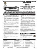
Figure 1 – ISSC / ISSD Configured f or 6-wire Load Cell and Two Status Inputs
ISSC / ISSD input module showing 6-wire load cell configu-
ration and two status inputs connected to limit s witches.
Note:
Both status excitation headers are in the ON position to pro-
vide voltage transition from +24 V to 0 V on switch closure.
Load cell header selected for 6-wire load cell.
Programming Quick Start Guide
Table 1: ISSC / ISSD 11-pin I/O Connector
Pin Description Function
1
2
3
4
5
6
7
8
9
10
11
–Sense
+EXC
+Sense
+Signal
–Signal
–EXC
Shield
+24 V
D1
D2
GND
Bridge – sense volts
Bridge + volts excitation
Bridge + sense volts
Bridge + signal output
Bridge – signal output
Bridge – volt excitation
Cable shield (+2.5 volt)
Not connected
Status input D1 (CH1)
Status input D2 (CH2)
Common ground
4 W
6
W
PIN 1
PIN 2
PIN 3
PIN 4
PIN 5
PIN 6
PIN 7
PIN 8
PIN 9
PIN 10
PIN 11
INPUT HI
INPUT LOW
EXC
+ EXC
GUARD
+ 24 V
GND
D1
N/C D2
+ SENSE
+ SUPPLY
SUPPLY
SIGNAL
PROXIMITY SWITCH POWERED BY INPUT MODULE.
(OPEN - COLLECTOR NPN TRANSISTOR OUTPUT)
N / C SENSE
368
A
D1
D2
Load Cell Header set for 4-wire.
Status Excitation Headers D1 & D2.
LOAD CELL
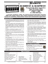
Figure 2 – ISSC / ISSD Configured f or 4-wire Load Cell and One Status Input
ISSC / ISSD input module sho wing 4-wire load cell config-
uration and one status input connected to a pro ximity
switch.
Status input D1 is the signal from an open collector NPN
transistor output in a pro ximity detector. Status e xcitation
header D2 must be in the ON position f or the tr ansistor to
provide +24 V to GND voltage transitions.
D2 is not connected.
Table 1: ISSC / ISSD 11-pin I/O Connector
Pin Description Function
1
2
3
4
5
6
7
8
9
10
11
–Sense
+EXC
+Sense
Input High
Input Low
–EXC
Shield
+ 24 V
D1
D2
GND
Not connected
Bridge + volts excitation
Bridge + sense volts
Bridge + signal output
Bridge – signal output
Bridge – volt excitation
Cable shield (+2.5 volt)
+ 24 V excitation
Status input D1 (CH1)
Not connected
Common ground

ISSC-D Data Sheet (NZ348) Page 3Texmate, Inc. Tel. (760) 598-9899 • www.texmate.com
Figure 3 – ISSC / ISSD Signal Flo w Diagram
-
S
EN
SE
+ EXC
+
S
EN
SE
+
S
I
G
NA
L
- EX
C
-
S
I
G
NA
L
Input Module ISSC / ISSD
PCB 368
2C
CH3
CH4
Low-noise
+5 V (130 mA)
Bridge Excitation
Di
g
ita
l
Si
g
na
l
Pr
o
cess
or
+24 V
GND
+5 V
Load
Cell
CH1
TIGER 320
SERIES
METER
D1
CH2
D2
Status Inputs
16-bi
t
Ra
t
i
o
me
t
ri
c
A
/
D Converte
r
Technical Description
Load Cell
Input Signal
CODE 2 SMART REGISTER 1 SETUP OUTPUT REGISTER MAP
Enter Code 2.
Select smart register 1
setup [X77].
SMT1 allows you to enter the
smart register 1 setup and
select for the load cell sensor:
•Line Frequency.
•Sensor Input.
•Output Rate.
The output register
map allo ws y ou to
choose a selection of
processed output sig-
nals from the load cell
input to either CH1 or
CH2.
CH3
CH4
Figure 4 – ISSC / ISSD Smar t Setup Register Operational Flow Diagram
Smart Setup Registers
SMART REGISTER 3 SETUP
Not required.
SMART REGISTER 2 SETUP
Not required.
The Tiger meter uses three smar t setup registers to configure all smar t input modules . ISSC / ISSD
requires only smart register 1 (SMT1) to be configured. See Figure 4.
SMT1 configures the load cell input signal for line frequency rejection, input signal range in mV/V, and out-
put rate. SMT1 produces the following six output registers from the load cell input:
•Averaged signal.
•Rapid response signal*.
•Peak signal*.
•Valley signal*.
•Capture signal**.
•Rate-of-change signal.
One of these registers can be tr ansferred to Channel 3 (CH3) via Code 2, the same or another register to
CH4 via Code 6.
Note:
* Signal output at the A/D sampling rate.
** Hardware initiated from meter CAPTURE pin.
The load cell input signal is processed in the input module ’s 16-bit A/D converter and digital signal proces-
sor from where it can be fed to either channel 3 (CH3) or channel 4 (CH4) or both. Status input D1 is inter-
nally assigned to channel 1 (CH1) and status input D2 is inter nally assigned to channel 2 (CH2).
CH1 is configured f or frequency measurement f or D1 in Code 2. CH2 is configured f or frequency meas-
urement for D2 in Code 4. Selecting the load cell output f or CH3 is configured in Code 5 and f or CH4 in
Code 6.
The line frequency rejection setting, sensor input r ange in mV/V, and the output rate are all selected in the
smart register 1 (SMT1) menu in Code 2.

Texmate, Inc. Tel. (760) 598-9899 • www.texmate.comPage 4 ISSC-D Data Sheet (NZ348)
Programming Procedures
2
1
MEASUREMENT TASK
0 Voltage, Current
1 TC (3rd digit selects type of TC)
2 RTD 3-wire (3rd digit selects type
of RTD)
3 RTD 2- or 4-wire (3rd digit selects
type of RTD)
4 Frequency
5Period
6 Counter
7 Smart Input Module
SECOND DIGITFIRST DIGIT
This setting enters the smart register 1 code
setup menu.
Press the and buttons at the same time to enter the main programming mode.
P
Press the button three times to enter Code 2. Set Code 2 to [X77].
P
OUTPUT REGISTER MAP
0 Average Signal
1 Rapid Response Signal*
2 Peak Signal*
3 Valley Signal*
4 Capture Signal**
5 Rate of Change Signal
6-
7 Smart input module register 1
code setup
THIRD DIGIT
0 10 Hz
1 10 Hz
2 100 Hz
3 100 Hz
TIGER PROCESSING RATE
Note the output registers in the 3rd digit
are specific to the ISSC / ISSD input mod-
ule. These registers vary for each different
smart input module.
Note:
* Signal output at the A/D sampling rate.
** Hardware initiated from meter CAPTURE pin.
3
SENSOR INPUT mV/V
0 1 mV/V
1 2 mV/V
2 3 mV/V
3 20 mV/V
4-
5-
6-
7-
SECOND DIGIT
OUTPUT RATE
0 1 Hz average, 50/60 Hz rapid response
1 10 Hz average, 50/60 Hz rapid response
2-
3 50/60 Hz average, 800/960 Hz rapid response
4-
5-
6-
7-
THIRD DIGIT
FIRST DIGIT
0 60 Hz rejection
1 -
2 50 Hz rejection
3 -
This menu provides settings unique
to smart register 1 of input module
ISSC/ISSD.
Press the button to enter SMT1.
P
Using the buttons,
select:
1st Digit:50 Hz line frequency rejection for 50 Hz power supply areas, or 60 Hz line frequency
rejection for 60 Hz power supply areas.
2nd Digit: The sensor input range.
3rd Digit: The output rate.
4
LINE FREQUENCY SELECT
5Press the button. The display returns to [Cod_2] [X77].
P
6Using the button, reset the 3rd digit to z ero [X70] to leave the smart register 1 menu.
Note, leaving the 3rd digit as 7 means the displa y constantly cycles between [Cod_2] and [SMt1].
Press the buttons to return to the operational display.
7
The f ollowing prog ramming procedures co ver all the steps required to configure smar t input module
ISSC/ISSD:
Steps 1 to 7: Code 2 – SMT1 –1) Line frequency rejection.
2) Signal range in mV/V.
3) Output rate.
Steps 8 to 9: Code 2 – CH1 –Frequency range for status input D1.
Steps 10 to 12: Code 4 – CH2 –Frequency range for status input D2.
Steps 13 to 14: Code 5 – CH3 –Output register for load cell input.
Steps 15 to 16: Code 6 – CH4 –Output register for load cell input.
SMT1 Setup
Enter Code 2 and then enter SMT1 to configure line frequency rejection, signal r ange , and output rate settings.

ISSC-D Data Sheet (NZ348) Page 5Texmate, Inc. Tel. (760) 598-9899 • www.texmate.com
Channel Setup Configure the required channel for each input signal type
Status Input D1: Set up CH1 in Code 2.
Status Input D2: Set up CH2 in Code 4.
Load Cell Input: Set up CH3 in Code 5 or CH4 in Code 6.
Status Input D1
Enter Code 2 and select the frequency r ange for CH1.
CH2
Set Code 4 to [3X0] to configure status input D2 on CH2.
1st Digit: Select 3to enter the second digital input men u.
2nd Digit: Select the frequency range for digital input D2.
3rd Digit: Select 0to apply No user defined linearization on CH2 .
MEASUREMENT TASK
0 Voltage, Current
1 TC (type as per 2nd digit)
2 RTD (type as per 2nd digit)
3 Second Digital Input
Channel (type as per 2nd
digit)
FIRST DIGIT
DIGITAL INPUT FREQUENCY RANGE
0 99.999 Hz range from 0.001 Hz
1 999.99 Hz range from 0.01 Hz
2 99.999 kHz range from 1 Hz (1 s gate)
3 500 kHz range from 10 Hz (0.1 s gate)
4-
5-
6-
7-
SECOND DIGIT
CH1 FREQUENCY RANGE SELECTION
0 99.999 Hz range from 0.010 Hz
1 99.999 Hz range from 2.000 Hz
2 999.99 Hz range from 0.01 Hz
3 999.99 Hz range from 2.00 Hz
4 9999.9 Hz range from 0.1 Hz
5 9999.9 Hz range from 2.0 Hz
6 99 kHz range from 1 Hz (1 s gate)
7 655.35 kHz range from 10 Hz (0.1 s gate)
THIRD DIGIT
FIRST DIGIT
0 10 Hz
1 10 Hz
2 100 Hz
3 100 Hz
TIGER PROCESSING RATE
Press the and buttons at the same time again to re-enter the main
programming mode, then press the button three times to enter Code 2.
P
P
Press the button twice to enter Code 4.
P
8
9
MEASUREMENT TASK
0 Voltage, Current
1 TC (3rd digit selects type of TC)
2 RTD 3-wire (3rd digit selects type
of RTD)
3 RTD 2- or 4-wire (3rd digit selects
type of RTD)
4 Frequency
5Period
6 Counter
7 Smart Input Module
SECOND DIGIT
Status Input D2
Enter Code 4 and select the digital input f or CH2.
10
11
12
32-POINT LINEARIZATION FOR CH2
THIRD DIGIT
0 No user defined Linearization on
CH2
1 32-point Linear ization on CH2 using
Ta bl e 1
2 32-point Linear ization on CH2 using
Table 2. See Note 5
3 32-point Linear ization on CH2 using
Table 3. See Note 5
4 32-point Linear ization on CH2 using
Table 4. See Note 5
5 125-point Linearization on CH2 (Tables
1 to 4 cascaded). See Note 5
6 –
7 –
Press the button to exit Code 4 and enter Code 5.
P
Set Code 2 to [X4X] to configure status input D1 on CH1.
1st Digit: Not relevant digital input D1.
2nd Digit: Select 4to enter the frequency range menu for digital input D1.
3rd Digit: Select the required frequency r ange setting for digital input D1.

Texmate, Inc. Tel. (760) 598-9899 • www.texmate.comPage 6 ISSC-D Data Sheet (NZ348)
MEASUREMENT TASK
0 No Function
1 Voltage, Current
2 TC (3rd digit selects type of TC)
3 RTD/Resistance (3rd digit selects type)
4 Real-time Cloc k & Timer (3rd digit
selects type)
5-
6-
7 Smart Input Module
SECOND DIGITFIRST DIGIT
OUTPUT REGISTER MAP
0 Average Signal
1 Rapid Response Signal*
2 Peak Signal*
3 Valley Signal*
4 Capture Signal**
5 Rate of Change Signal
6-
7 Smart input module register 1 code
setup
THIRD DIGIT
0 Direct Displa y of Input (no
processing)
1 Square Root of Channel 3
2 Inverse of Channel 3
3Meters with 4 kB memor y
NO Linearization
Meters with 32 kB memory
32-point Linear ization of
CH3 using Table 3
Note:
All linear ization tab les are
set up in the Calibr ation
Mode [24X].
TIGER PROCESSING RATE
Note, the output registers in the 3rd
digit are specific to the ISSC / ISSD
input module. These registers vary for
each different smart input module.
Load Cell Input
The load cell input can be selected f or CH3 via Code 5 or CH4 via Code 6.
Set Code 5 to [07X] and select the required load cell output register f or CH3 in the 3rd digit.
1st Digit: Set to 0to select Direct Display of Input.
2nd Digit: Select 7to enter the output register map for the load cell signal.
3rd Digit: Select the required output register setting f or the load cell signal.
14
13
CH3
Press the button to exit Code 5 and enter Code 6.
P
Press the and buttons at the same time to retur n to the operational display.
P
Press the button to save the settings.
P
CH4
16
17
If a load cell output is required on CH4 set Code 6 to [07X] and select the required load cell output register f or
CH4 in the 3rd digit.
1st Digit: Set to 0to select Direct Display of Input.
2nd Digit: Select 7to enter the output register map for the load cell signal.
3rd Digit: Select the required output register setting f or the load cell signal.
MEASUREMENT TASK
0 No Function
1 Voltage, Current
2 TC (3rd digit selects type of TC)
3 RTD/Resistance (3rd digit selects type)
4 Real-time Cloc k & Timer (3rd digit
selects type)
5-
6-
7 Smart Input Module
SECOND DIGITFIRST DIGIT
OUTPUT REGISTER MAP
0 Average Signal
1 Rapid Response Signal*
2 Peak Signal*
3 Valley Signal*
4 Capture Signal**
5 Rate of Change Signal
6-
7 Smart input module register 1 code
setup
THIRD DIGIT
0 Direct Displa y of Input (no
processing)
1 Square Root of Channel 3
2 Inverse of Channel 3
3Meters with 4 kB memor y
NO Linearization
Meters with 32 kB memory
32-point Linear ization of
CH3 using Table 3
Note:
All linear ization tab les are
set up in the Calibr ation
Mode [24X].
TIGER PROCESSING RATE
Note, the output registers in the 3rd
digit are specific to the ISSC / ISSD
input module. These registers vary for
each different smart input module.
15

ISSC-D Data Sheet (NZ348) Page 7Texmate, Inc. Tel. (760) 598-9899 • www.texmate.com
CODE 2
Example Setup Procedure
In our example, a hopper fills boxes travelling along a conveyor belt. A rotary encoder monitors the conveyor
speed and a light beam sensor indicates when the bo x to be filled is in position belo w the hopper. A load cell
under the conveyor weighs the box.
The rotary encoder is connected to status input D1 and assigned to CH1. The light beam sensor is connected
to status input D2 and assigned to CH2. The load cell is configured for 3 mV/V input with 50 Hz line frequency
rejection. As the boxes are filled relatively quickly, the averaged output rate is set to 10 Hz on CH3.
The frequency output from the encoder is in the 0 to 1 kHz r ange (360 pulse/revolution). The light sensor has its
beam broken at a much slower rate.
1Set up smart register 1 (SMT1) for 50 Hz line rejection, a 3 mV/V range, and 10 Hz averaged output rate:
In select X77 then press the button.
P
SMt1 000
Set 231
Display toggles between
SMt1 to
CODE 2
2Select the 1 kHz frequency range for the encoder on CH1:
In reset to X42 then press the button twice.
P
3
SP1 SP2 SP3 SP4 SP5 SP6
Prog.
kg
DI-50 TIGER 320 SERIES
Light
Sensor
Load Cell
Rotary encoder
feedback for
motor speed
control
Speed
Controller
Relay Outputs
D1 (CH1)
Weight
CH3 or CH4
D2 (CH2)
Hopper Gate
CODE 4
Select the slowest frequency range for the light sensor on CH2:
In select 30X then press the button.
P
Figure 5 – Load Cell with Dual Status Inputs
4
CODE 5
Select the averaged load cell signal for CH3:
In select X70 then press the button.
P
Press the and buttons at the same time to enter the main prog ramming mode. Press the
button three times to enter Code 2.
P
P
Press the and buttons at the same time to retur n the main programming mode.
P

Texmate, Inc. Tel. (760) 598-9899 • www.texmate.comPage 8 ISSC-D Data Sheet (NZ348)
Customer Configuration Settings:
1st Digit 2nd Digit 3rd Digit
1st Digit 2nd Digit 3rd Digit
CH3
CH4
CH2
1st Digit 2nd Digit 3rd Digit
1st Digit 2nd Digit 3rd Digit
1st Digit 2nd Digit 3rd Digit
CH1
7
7
4
30
0
0
WARRANTY
Texmate warrants that its products are free from def ects in mater ial and w orkmanship under
normal use and ser vice for a per iod of one y ear from date of shipment. Texmate’s obligations
under this warranty are limited to replacement or repair, at its option, at its factory, of any of the
products which shall, within the applicable period after shipment, be returned to Texmate’s facil-
ity, tr ansportation charges pre-paid, and which are , after e xamination, disclosed to the satis-
faction of Texmate to be thus def ective. The warranty shall not apply to an y equipment which
shall have been repaired or altered, except by Texmate, or which shall have been subjected to
misuse, negligence , or accident. In no case shall Texmate’s liability e xceed the or iginal pur-
chase price. The aforementioned provisions do not e xtend the or iginal warranty period of any
product which has been either repaired or replaced b y Texmate.
USER’S RESPONSIBILITY
We are pleased to offer suggestions on the use of our v arious products either by way of print-
ed matter or through direct contact with our sales/application engineering staff. However, since
we ha ve no control o ver the use of our products once the y are shipped, NO WARRANTY
WHETHER OF MERCHANT ABILITY, FITNESS FOR PURPOSE, OR O THERWISE is made
beyond the repair, replacement, or refund of purchase pr ice at the sole discretion of Texmate.
Users shall deter mine the suitability of the product f or the intended application bef ore using,
and the users assume all risk and liability whatsoever in connection therewith, regardless of any
of our suggestions or statements as to application or constr uction. In no event shall Texmate’s
liability, in law or otherwise, be in excess of the purchase pr ice of the product.
Texmate cannot assume responsibility for any circuitry described. No circuit patent or software
licenses are implied. Texmate reserves the right to change circuitry, operating software, speci-
fications, and prices without notice at any time.
For product details visit www.texmate.com
Tel: 1-760-598-9899 • USA 1-800-839-6283 • That’s 1-800-TEXMATE
Email: [email protected] • Web: www.texmate.com
1934 Kellogg Ave. • Carlsbad, CA 92008
/