Page is loading ...
PRODUCT DATA
66-1171-03
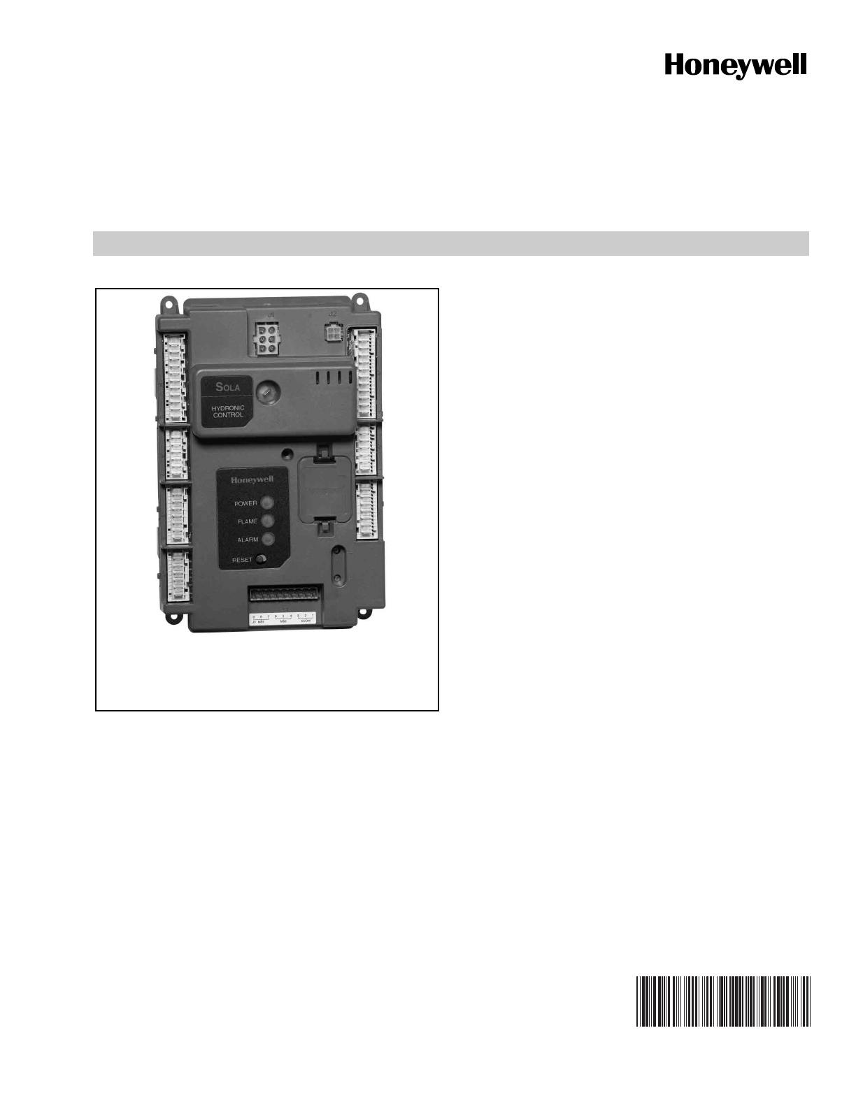
R7910A SOLA HC (Hydronic Control)
R7911 SOLA SC (Steam Control)
APPLICATION
The R7910A SOLA HC is a hydronic boiler control system and
the R7911 SOLA SC is a Steam Control system that provide
heat control, flame supervision, circulation pump control, fan
control, boiler control sequencing, and electric ignition
function. It will also provide boiler status and error reporting.
Multiple boilers can be joined together to heat a system
instead of a single, larger burner or boiler. Using boilers in
parallel is more efficient, costs less, reduces emissions,
improves load control, and is more flexible than the traditional
large boiler.
R7910A Hydronic Control shown.
For R7911, “Steam Control” would replace
“Hydronic Control” on label.
SOLA HC/SC System may Consist of:
R7910/R7911 Control Device
S7999B Touchscreen Display—required for setup and ModBus communication but not required for the system to operate once
the R7910A/R7911 is programmed.
S7999C Local Operator Interface, which can setup and monitor the R7910/R7911.
S7910A Local Keyboard Display Module
Flame Rod or UV flame detector (C7027, C7035, or C7044)
Temperature Sensor, NTC Type 10KΩ at 77°F (25°C) or 12KΩ at 77°F (25°C)
Limit Sensor, NTC Type 10KΩ at 77°F (25°C)
Fans (VFD)
R7911 uses a Steam Sensor, 0-15 or 0-150 psi - 4-20mA source type

R7910A SOLA HC (HYDRONIC CONTROL) R7911 SOLA SC (STEAM CONTROL)
66-1171—03 2
FEATURES
Safety and Boiler Protection
R7910 Hydronic Control
• Frost Protection, Slow Start, Anti-condensate, Boiler
Delta-T, Stack Limit, Boiler Limit, DHW Limit, Outlet T-
Rise Limit
R7911 Steam Control
• Slow Start, Stack Limit
Integrated Control Functions
• Primary Flame Safeguard Control
• Internal or external spark generator
• Algorithm Prioritization
• Firing Rate Limiting
• R7910 Hydronic Control
• Anti-Condensate, Stack Limit, Boiler
Delta-T,
• Boiler Slow Start, Outlet Limit
• R7911 Steam Control
• Stack Limit
• PID Load Control
• R7910 Hydronic Control
• CH (Central Heat)
• DHW (Domestic Hot Water)
• R7911 Steam Control
•Steam
• Remote Reset
• TOD (Time of Day)
• PWM for Variable Frequency Drives
• Auxiliary Output Control
• R7910 Hydronic Control for Pumps
• 3 outputs, 5 different programmable
features)
• R7911 Steam Control
• 3 programmable output features
• Burner Demand sources
• R7910 Hydronic Control
• CH, DHW and Frost Protection
• R7911 Steam Control
• Steam sensor
• Loops of Control
• R7910 Hydronic Control has two loops of
Control
•CH
• DHW
• R7911 Steam Control has One loop of Control
•Steam
• High Limit and Control (Meets UL 353)
• R7910 Hydronic Control
• CH, DHW and Stack
• R7911 Steam Control
• Stack
• Fifteen Item Fault Code History including equipment
status at time of lockout
• Fifteen Item Alert Code Status including equipment
status at time of internal alerts
• 24Vac Device Power
• R7910: 24 or 120Vac Digital I/O models available.
• R7911: 120Vac Digital I/O
• Flame Signal test jacks (Vdc)
• Three Status LEDs
•Power
•Flame
•Alarm
• Flame Sensing
• Ultraviolet (C7027, C7035, C7044 Sensors)
•Flame Rod
• Single Element (Internal spark generator
and flame sense using the same element)
• Dual Element (separate elements for
ignition spark and flame sense)
Inputs
• Analog Inputs
• NTC Sensor Inputs (10kohm or 12kohm)
NOTE:12kohm and 10kohm single sensors cannot
be used for Limit Application functions
(10kohm dual sensors only).
• R7910 Hydronic Control
• Outlet Limit And Temperature
• DHW Limit and Temperature
• Stack Limit and Temperature
• Inlet Temperature
• Outdoor Temperature
• R7911 Steam Control
• Stack Limit and Temperature
• Other Analog Inputs
• PWM Feedback
• Flame Signal from either a Flame Rod or
Ultraviolet Detector
• R7910 and R7911: 4-20mA Control Input,
Remote Setpoint, Remote Firing Rate
• R7911: 4-20mA Steam Input Pressure (15
or 150 psi)
• Digital Inputs
• Pre Ignition Interlock (Programmable)
• LCI (Load [or Limit] Control Input)
(Programmable)
• Interlock (Programmable)
• Annunciation (8 Programmable) (6
Programmable plus High Fire and Low Fire
Switch Interlocks—model specific)
• Remote Reset
• TOD (Time of Day)
Outputs
• Analog Outputs
• Modulation
•4-20mA
•0-10 Vdc
• PWM for Variable Frequency Drives
• Digital Outputs
• Auxiliary Output Control
• R7910 Hydronic Control for Pumps
3 outputs, 5 different programmable
features)
• R7911 Steam Control
3 programmable output features
• Combustion Blower
• External Ignition
• Pilot Valve
•Main Valve
•Alarm
R7910A SOLA HC (HYDRONIC CONTROL) R7911 SOLA SC (STEAM CONTROL)
366-1171—03
Models Available:
* Contains built in anticipation for Low Voltage Stat Input
Table 1. SOLA HC/SC Models Available.
Model Hydronic/Steam Digital I/O Modulation Output
Flame
Detection HFS/LFS Inputs
R7910A1001 Hydronic 24V PWM 4-20mA 0-10V FR/UV
R7910A1019 Hydronic 120V PWM 4-20mA 0-10V FR/UV BOTH
R7910A1027 Hydronic 120V PWM 4-20mA 0-10V FR/UV
R7910A1084* Hydronic 24V PWM 4-20mA 0-10V FR *
R7911A1000 Steam 120V PWM 4-20mA 0-10V FR/UV
R7911A1026 Steam 120V PWM 4-20mA 0-10V FR/UV BOTH

R7910A SOLA HC (HYDRONIC CONTROL) R7911 SOLA SC (STEAM CONTROL)
66-1171—03 4
TABLE OF CONTENTS
Application ......................................................................................................................................................... 1
Features ............................................................................................................................................................. 2
Overview ............................................................................................................................................................ 9
Installation .......................................................................................................................................................... 11
Wiring ................................................................................................................................................................. 12
Startup ................................................................................................................................................................ 19
Parameter Control Blocks (PCB) ....................................................................................................................... 19
Programming Safety Parameters ....................................................................................................................... 20
Annunciator ........................................................................................................................................................ 62
Functional Sub Systems .................................................................................................................................... 20
Demand and Rate ....................................................................................................................................... 23
CH Hydronic Loop Demand and Rate ........................................................................................................ 25
DHW Loop Demand and Rate (Hydronic only) ........................................................................................... 34
Frost Protection (Hydronic only) ................................................................................................................. 41
Rate Limits and Override ............................................................................................................................ 44
Anticondensation (Hydronic Control) .......................................................................................................... 51
The Burner Control Uses: ........................................................................................................................... 57
Modulation Output ...................................................................................................................................... 51
Pump Control .............................................................................................................................................. 54
Fault Handling .................................................................................................................................................... 64
Lockouts and Alerts .................................................................................................................................... 64
Alarms for Alerts ......................................................................................................................................... 64
Burner Control Operation ................................................................................................................................... 65
Safety Shutdown of Burner Control Functions ............................................................................................ 65
Operational Sequence ................................................................................................................................ 65
Appendix A: Parameter Glossary ....................................................................................................................... 91
Appendix B: Hydronic Device Parameter Worksheet Example .......................................................................... 102
R7910A Lockout and Hold Codes. ..................................................................................................................... 107
PREFACE
This Product Data sheet is intended to provide a general
overview of the R7910 SOLA HC and R7911 SOLA SC. The
chosen set of parameters for a certain boiler type needs to be
functionally tested for correct operation.
This document is a textbook version of the parameters. The
glossary beginning on page 91 provides an abbreviated
parameter explanation along with a reference page for a more
in-depth explanation.
The actual setup of the R7910 or R7911 is accomplished using
the S7999B System Operator Interface, the DSP3944 Setup
Tool, or the S7999C Local Operator Interface. Refer to form
66-1170 for the S7999B or 65-0303 for the S7999C operation
and setup screens. This document will assist in understanding
the parameters being setup.
Appendix B is a worksheet example of a R7910 device
parameters and how they might be setup to provide a system
function.
Note that this sheet (like the S7999B System Operator
Interface and S7999C Local Operator Interface) shows most
available parameters. The actual product may have
parameters made invisible or read-only by the OEM, as they
apply for their product.
The chosen set of parameters for a certain boiler type MUST
be functionally tested for correct operation.

R7910A SOLA HC (HYDRONIC CONTROL) R7911 SOLA SC (STEAM CONTROL)
566-1171—03
FEATURES, continued
Access codes through the display allow for different levels of
setup.
— The OEM level allows for equipment to operate within
guidelines that they feel necessary for safe and effi-
cient operation of their equipment. The OEM makes
available the parameters that the installing contractor
needs for installation adjustments of the equipment.
— The installer setup information is customized by the
OEM. The access code for the installer level must be
obtained from the OEM.
— The User level allows for non critical adjustments for
the individual piece of equipment. These would include
but not limited to:
• Read the error log from R7910A/R7911.
• Monitor the input and output variables of the
controller.
• Read parameters from R7910A/R7911.
• CH and DHW setpoint adjustment.
Operational Features
Self Test
The Safety Processor performs Dynamic Self Checks that
supervise microcomputer performance to ensure proper
operation. The microcomputer tests itself and its associated
hardware with comprehensive safety routines. Any malfunction
will be detected by the microcomputer to cause a safety
shutdown and cause the Dynamic Safety Relay to de-energize
all safety-critical loads.
Initialization
The R7910A/R7911 will start up in either the configured or
unconfigured condition. In the Configured condition it is ready
to operate a burner.
The R7910A/R7911 is in the unconfigured condition whenever
a safety parameter requires editing (Commissioning). The
R7910A/R7911 remains unconfigured and will not operate a
burner until all safety parameters have been reviewed and
confirmed.
Safety Lockout
The R7910A/R7911 can be set up to maintain a lockout
condition on power interruption or to reset the lockout on a
power interruption.
Reset
Pressing and releasing the reset button (or the remote reset
input) causes a lockout condition to be cleared, and the
microcomputer that operates the burner control part of the
R7910A/R7911 to reinitialize and restart.
A safety lockout can also be reset through a writable
parameter from the system display through Modbus.
Fault Handling
The R7910A/R7911 implements two kinds of faults: lockouts
and alerts.
Lockout messages are stored in the R7910/R7911 non-volatile
memory (File and lockout remain with power interruption) and
Alerts are stored in the volatile memory (file clears on power
interruption).
•Lockout causes the burner control to shutdown and
requires manual or remote reset to clear the lockout.
• It always causes the alarm contact to close.
• Gets logged into the 15 item lockout history.
•Alerts include every other kind of problem that does not
shut the burner down. Examples of alerts are faults from
non–safety functions or abnormal events that are relevant
to an operator or end user.
• Alerts never require manual intervention to reset
them (an alert is not a condition, it is an event).
• Whether the alarm contact closes or not is
programmable by the OEM for each alert.
• Alerts are logged in the 15 item alert history and
sorted in chronological order. Only one instance of
each alert fault code occurs in the history,
corresponding to the most recent occurrence of the
alert.
Sensor Select
Inputs for Header or Outdoor temperature sensors might be
available from various sources, so parameters are provided to
select the input source. These parameters determine:
• how temperatures are obtained;
• if/where temperature information is stored;
• where a control loop gets its data.
Sensor Signal Conditioning
The analog sensors signal includes filtering to reduce the effect
of noise and spurious read events. This filter includes
averaging to smooth sensor output and reject occasional
spurious values to prevent them from affecting the average.
Sensors won’t cause a fault condition unless the value is
requested for control purposes. Thus it is not a fault for a
sensor to be absent or otherwise non-operational unless it is
used for something (i.e. outdoor temperature).
If its value is requested and a sensor fault exists, then an alert
condition is triggered by the requestor in response to the fault
status, unless this is either a normal operating condition (e.g.,
the DHW sensor used as a switch) or causes a lockout (e.g., a
failed high limit sensor).
Safety sensors include the comparison of redundant sensors.
If a safety sensor mismatch occurs this is reported to the caller
as a fault (which will cause the operator to take an appropriate
action).
Sensor faults will include:
• out-of-range: low
•out-of-range: high—distinguishing low vs. high is
important when sensor inputs are being used as digital on/
off inputs; in this case these out-of-range values are not
faults.
•mismatch—applies to safety sensors, where two sensors
are compared.

R7910A SOLA HC (HYDRONIC CONTROL) R7911 SOLA SC (STEAM CONTROL)
66-1171—03 6
Non-Volatile Memory
The R7910A/R7911 will store the following items in non-volatile
memory (Information remains in control on power interruption):
• Factory configuration data
• Parameter Control Blocks (for example, Read only and
Password Settings)
• All configuration parameters
• The 15 item lockout history
• Cycle and Time history
Lockout History
The lockout history contains 15 records. Each record is a
snapshot of the following values as they existed at the time of
the lockout.
•Burner Lockout/Hold identifies the cause of the lockout.
•Burner State identifies the state of the burner control (e.g.
standby, purge, run).
•Burner Displayed Time: mm:ss is the displayed timer
used by the Burner Control at the time of lockout (e.g.
prepurge time, ignition time, etc.).
•Annunciator First-out is the first-out code for the lockout.
•Burner Run Time is the elapsed time of burner operation.
•Burner Cycle Count is the number of burner cycles (based
on the main valve being turned on).
• All analog sensor values (Inlet, Header, Outlet, Outdoor,
DHW, Stack, or Steam)
Cycle and Time History
The non-volatile memory contains the following parameters
and status values related to cycle counts and elapsed
operation time:
• Burner Run Time: hhhhhh:mm
• Burner cycle count: 0-999,999
• CH cycle count: 0-999,999
• DHW cycle count: 0-999,999
• Boiler pump cycle count: 0-999,999
• Auxiliary pump cycle count: 0-999,999
• System pump cycle count: 0-999,999
These are writable parameters so they may be altered if the
R7910A/R7911 is moved, the burner is replaced or some
component is replaced.
There are also two non-writable counters:
• Controller Run Time: hhhhhh:mm
• Control cycle count: 0-999,999
Flame Signal Processing
The flame signal processing will monitor either a flame rod or a
UV flame sensor. The flame signal voltage at the test jacks or
on the bar graph on the display is the measured voltage in the
range from 0V to 15V. The display could show stronger
numerical data.
The incoming flame signals are filtered to eliminate transient
and spurious events.
The Flame failure response time (FFRT) is 4 seconds.
Flame sensitivity is set by the Flame Threshold parameter,
which will provide the ON/OFF threshold specified in volts or
microamps (1 volt is equivalent to 1 microamp).
Temperature Settings
All parameters that provide a temperature have a possible
value of “None.”
This value is a special code that is not a legal temperature. If
the R7910/R7911 Control is configured with a “none”
temperature, then this setting must be set up by the installer
before the control will operate.
Modbus/ECOM Event Handling
The Modbus and ECOM communication system responds to
queries and can write new values to the parameters. See
Product Data Sheet 65-0310 for software interface
specifications (ModBus).
WARNING
Explosion Hazard.
Improper configuration can cause fuel buildup and
explosion.
Improper user operation may result in property loss,
physical injury, or death.
The S7999B1026 System Operator Interface or
S7999C Local Operator Interface used to change
Safety Configuration Parameters is to be done only by
experienced and/or licensed burner/boiler
operators and mechanics.
Response to Writing:
• Safety parameters will cause a lockout and must be
reviewed and verified before the control will operate again.
• Non-safety parameters may be written at any time and will
become effective within a short time; however, any behavior
that is seeded by the parameter value and is currently in-
progress (e.g. a delay time) may not respond to the change
until the next time this behavior is initiated.
Required Components (not supplied)
Dual Element Sensor contains Sensor plus Limit (10kohm,
Beta = 3950). Note: 12kohm sensors with Beta of 3750 may
be used as sensors, but not as safety limits.
• 50001464-006 6” with Molex splice connector
• 50001464-007 42” without connector
Single Element Sensor only (10 kohm, Beta = 3950)
• 198799Z 42" leads without connector
• 32003971-002 6" leads with Molex Splice Connector
• 32003971-003 CONTAINS:
(1) 198799Z sensor with 42" leads
(2) 118826 ANCHORS;
(3) 199624AB MTG. SCREWS;
(2) 121958 WIRE NUTS;
(1) 32002217-002 SENSOR CLIP;
(2) 291125 TIE STRAP
• UV Flame Sensor - C7027, C7035, or C7044
• Flame Rods - C7007, 8, 9
• Pilot Burner Assemblies - Q179A, C, C7005
• External Ignition Transformer - Q624A1014, Q652B1006
• Gas Valves - Solenoid V8295 (24Vac),
V4295/7 (120Vac)
Fluid Power V4055 (120 Vac) with
V5055 or V5097
V4730/V4734/V8730 Premix valves
with Venturi
• Modulation Motor - M7294 (4-20 ma or 0-10Vdc)

R7910A SOLA HC (HYDRONIC CONTROL) R7911 SOLA SC (STEAM CONTROL)
766-1171—03
• Transformer (for powering R7910/R7911 40va minimum) -
AT72D (40VA) AT88 (75VA)
• R7911 - Pressure Sensor (15 or 150) 4-20mA source type
• 50032893 - 001 Bag of connectors
Required but purchased outside Honeywell:
• Circulating Pumps 24 or 120 Vac
• Blower Motor, on/off or VFD

R7910A SOLA HC (HYDRONIC CONTROL) R7911 SOLA SC (STEAM CONTROL)
66-1171—03 8
Connectors for field wiring: May be obtained separately outside Honeywell. See list below.
Accessories:
• S7910A Local Keyboard Display Module
• S7999B System Operator Interface
• DSP3944 System Display for system Setup when S7999B or S7999C not required.
• PM7910 Program Module - Storage module for the R7910 non-safety setup parameters, may be written to for storage or used
for configuration of replacement controls or multiple systems, Commands given from any display interface through the R7910.
• S7999C1008 Local Operator Interface
• 50031353-001 Software Configuration Tool
ICP Device Mates with …
Plug # Description Manf. Part Number
J1 Flame Detection
Interface
Molex 0050841060 (Shell), 0002081002 (Pin, 14-20 AWG)
J2 PWM Combustion
Blower Interface
Molex 0039012040 (Shell), 0039000059 (Pin, 18-24 AWG)
J3 Comm. Interface OST EDZ1100/9 (SCREW)
J4 Line Voltage I/O Lumberg 3623 06 K129 (IDC, Pins 1 - 6) 3615-1 06 K129 (SCREW, Pins 1 - 6)
3623 06 K130 (IDC, Pins 7 - 12) 3615-1 06 K130 (SCREW, Pins 7 - 12)
J5 Line Voltage I/O Lumberg 3623 07 K01 (IDC) 3615-1 07 K01 (SCREW)
J6 Line Voltage I/O Lumberg 3623 08 K43 (IDC) 3615-1 04 K185 (SCREW, Pins 1- 4)
3615-1 04 K188 (SCREW, Pins 5- 8)
J7 Line Voltage I/O Lumberg 3623 07 K48 (IDC) 3615-1 07 K48 (SCREW)
J8 Low Voltage I/O Lumberg 3623 06 K127 (IDC, Pins 1 - 6) 3615-1 06 K127 (SCREW, Pins 1 - 6)
3623 06 K128 (IDC, Pins 7 - 12) 3615-1 06 K128 (SCREW, Pins 7 - 12)
J9 Low Voltage I/O Lumberg 3623 07 K59 (IDC) 3615-1 07 K59 (SCREW)
J10 High Voltage I/O Lumberg 3623 08 K64 (IDC) 3615-1 04 K187 (SCREW, Pins 1- 4)
3615-1 04 K186 (SCREW, Pins 5- 8)
J11 High Voltage I/O Lumberg 3623 07 K30 (IDC) 3615-1 07 K30 (SCREW)
R7910A SOLA HC (HYDRONIC CONTROL) R7911 SOLA SC (STEAM CONTROL)
966-1171—03
OVERVIEW
Functions provided by the R7910A/R7911 include automatic
boiler sequencing, flame supervision, system status indication,
firing rate control, load control, CH/DHW control, limit control,
system or self-diagnostics and troubleshooting.
The R7910 maximum version of the controller offers:
• NTC-temperature sensor for:
• Outlet Limit And Temperature
• DHW (Domestic Hot Water) Limit and Temperature
• Stack Temperature Limit and Temperature
• Inlet Temperature
• Outdoor Temperature (R7910 only)
• Modulating output PWM-driven rotation speed controlled
DC-fan for optimal modulation control.
• Three Pump Outputs with 5 selectable operation modes
• 24Vac or 120Vac (model specific) offer:
• Output control of gas valve (Pilot and Main) and
External Ignition Transformer
• Digital inputs for room limit control, high limit control,
Air pressure switch, Gas pressure switch, low water
cutoff, valve proof of closure switch.
• Optional switches:
• Time of Day switch
• Burner switch
• Remote Reset
• Easy modification of the parameters on three levels:
• End-user
• Installer / Service engineer
• Manufacturer
• Integrated spark transformer
• Optional external spark transformer
• Optional combined ignition and flame sensing
• Test jacks for flame signal measurement from either a flame
rod or UV flame sensor.
• Alarm Output
Fig. 1. General R7910 hydronic boiler schematic.
Fig. 1 shows two loops of heat control: Central Heating (CH),
and an optional second loop for Domestic Hot Water (DHW)
can be configured on each R7910A. The DHW loop transfers
heat from the boiler outlet to hot water appliances in
conjunction with the primary system heat loop. Priority
assignment to each heat loop can be configured to specify
which loop gets serviced first.
COMMUNICATIONS AND
DISPLAYS
Three modes of communications are available to the R7910.
• ECOM is used for the S7910 Local Keyboard display for
R7910/R7911 monitoring and changing setpoints. Some
equipment setup and checkout is available using the S7910
along with remote reset of a lockout on the R7910/R7911.
• The R7910/R7911 has two RS485 communication ports for
ModBus that allows for interfacing to one or all R7910/
R7911s of a system and presents them individually to the
user. The S7999B System Operator interface and S7999C
Local Operator interface are color touchscreen displays
used for configuration and monitoring of the R7910A/
R7911. Control Operation and display status in both test
and graphical modes can be shown along with the ability to
setup. The R7910/R7911 can also be remotely reset
through the S7999B/C display.
R7910
HEAT
LOAD
LOCAL
DISPLAY
T
OUTDOOR
TEMP
T
HEADER
TEMP
IGNITOR
FAN
ALARM
STACK
T
T
BOILER
OUTLET
T
T
INLET
FLAME SIGNAL
INTERLOCK(S)
PII
LIMIT(S)
A
NNUNCIATION (8)
REMOTE RESET
TOD
STAT
PILOT
VALVE
MAIN VALVE(S)
DOMESTIC
HOT WATER
TANK
BOILER
MIX
LOOP
DHW
LOOP
M27058
BUILDING
AUTOMATION
SYSTEM
WATER
OUTPUTS
INPUTS
KEY
COMMUNICATION
SYSTEM
DISPLAY
CH
LOOP

R7910A SOLA HC (HYDRONIC CONTROL) R7911 SOLA SC (STEAM CONTROL)
66-1171—03 10
• Either ModBus RS485 communication port can be used to
allow configuration and status data to be read and written to
the R7910/R7911. Support a Master S7999B or a Building
Automation master to control the R7910 or R7911 to
respond to a single ModBus address to service the requests
of the ModBus master in a Lead/Lag arrangement.
The local S7910 Keyboard display, the S7999B System
Operator interface, and the S7999C Local Operator Interface
are optional components.
The S7999B (or the DSP3944 which is a portable S7999B) or
the S7999C is required configuration of the parameters of the
R7910/R7911 but is not needed for the operation of the system
once configured.
SPECIFICATIONS
Electrical Ratings:
Operating voltage
24Vac (20 to 30 Vac, 60 Hz ±5%)
Connected Load for Valve and annunciator functions:
24Vac, 60Hz
120Vac (+10%/-15%), 60Hz (±5%)
Model Specific
Corrosion:
R7910A/R7911 should not be used in a corrosive environment.
Operating Temperature: -4°F to 150°F (-20°C to 66°C)
Storage/Shipping Temperature: -40°F to 150°F
(-40°C to 66°C).
Humidity:
Up to 95% Relative Humidity, noncondensing at 104°F for 14
days. Condensing moisture may cause safety shutdown.
Vibration: 0.0 to 0.5g Continuous (V2 level)
Enclosure: Nema 1/IP40.
Approvals:
Underwriters Laboratories, Inc. (UL)(cUL): Component Recog-
nized: File No. MP268 (MCCZ)
R7910 and R7911 are certified as UL372 Primary Safety
Controls.
The R7910 is certified as UL353 Limit Rated device when
using part number 50001464 dual element limit rated NTC
sensors.
CSD-1 Acceptable.
Meets CSD-1 section CF-300 requirements as a Primary
Safety Control.
Meets CSD-1 section CW-400 requirements as a Temperature
Operation control.
Meets CSD-1 section CW-400 requirements as a Temperature
High Limit Control when configured for use with 10kohm
NTC sensors.
Federal Communications Commission, Part 15,
Class B.Emissions.
Dimensions: See Fig. 2.

R7910A SOLA HC (HYDRONIC CONTROL) R7911 SOLA SC (STEAM CONTROL)
11 66-1171—03
Fig. 2. R7910A/R7911 dimensions in in. (mm).
* All sensors attached to the R7910 MUST be all 12K or 10K
sensors (don't mix and match).
INSTALLATION
WARNING
Fire or Explosion Hazard.
Can cause property damage, severe injury,
or death.
To prevent possible hazardous boiler operation, verify
safety requirements each time a control is installed on
a boiler.
WARNING
Electrical Shock Hazard.
Can cause severe injury, death or property damage.
Disconnect the power supply before beginning
installation to prevent electrical shock and equipment
damage. More than one power supply disconnect can
be involved.
[2] 5-19/64 (135)
9-21/64
(237) MAX
[4] Ø 3/16 (5) MAX
2-19/32 (66)
6-21/64 (161)
[2] 8-21/32
(220)
M27063
Table 2. NTC Sensors (temperature versus resistance).
Temp C (F)
12K NTC (kOhm)*
Beta of 3750
10K NTC (kOhm)*
Beta of 3950
-30 (-22) 171.70 176.08
-20 (-4) 98.82 96.81
-10 (14) 58.82 55.25
0 (32) 36.10 32.64
10 (50) 22.79 19.90
20 (68) 14.77 12.49
25 (77) 12.00 10.00
30 (86) 9.81 8.06
40 (104) 6.65 5.32
50 (122) 4.61 3.60
60 (140) 3.25 2.49
70 (158) 2.34 1.75
80 (176) 1.71 1.26
90 (194) 1.27 0.92
100 (212) 0.95 0.68
110 (230) 0.73 0.51
120 (248) 0.56 0.39

R7910A SOLA HC (HYDRONIC CONTROL) R7911 SOLA SC (STEAM CONTROL)
66-1171—03 12
When Installing This Product…
1. Read these instructions carefully. Failure to follow them
could damage the product or cause a hazardous condi-
tion.
2. Refer to the wiring diagram provided as part of the appli-
ance or refer to Fig. 3.
3. Check the ratings given in the instructions and on the
product to make sure that the product is suitable for your
application.
4. Installer must be a trained, experienced combustion ser-
vice technician.
5. Disconnect the power supply before beginning installa-
tion to prevent electrical shock and equipment damage.
More than one disconnect may be involved.
6. All wiring must comply with applicable local electrical
codes, ordinances and regulations.
7. After installation is complete, check out product opera-
tion as provided in these instructions.
Vibration
Do not install the relay module where it could be subjected to
vibration in excess of 0.5G continuous maximum vibration.
Weather
The relay module is not designed to be weather-tight. When
installed outdoors, protect the relay module using an approved
weather-tight enclosure.
Mounting The R7910/R7911
1. Select a location on a wall, burner or electrical panel.
The R7910/R7911 can be mounted directly in the control
cabinet. Be sure to allow adequate clearance for servic-
ing.
2. Use the R7910/R7911 as a template to mark the four
screw locations. Drill the pilot holes.
3. Securely mount the R7910/R7911 using four no. 6
screws.
NOTE: The device can be removed and replaced in the field
without rewiring.
WIRING
WARNING
Electrical Shock Hazard.
Can cause serious injury, death or property
damage.
Disconnect power supply before beginning wiring to
prevent electrical shock and equipment damage. More
than one disconnect may be involved.
Ground Connection
The ground connection on the controller must not be used as a
central ground connection for the 120 Vac connections.
1. Use the common ground terminal next to the controller,
close to connector J4 terminal 12.
2. Connect the central ground terminal with the connection
contact of the controller (connector J4 terminal 12).
3. Connect the ground wire of the main power connector,
the CH pump, the DHW pump (if present) and the igni-
tion wire to the central ground terminal.
Electrical Connections
1. Refer to Table 5 for terminal contact ratings.
2. Use 18 AWG or larger wires.
3. Wire according to specifications, following all local ordi-
nances and requirements.
Device Power Supply, 24Vac
1. 24Vac Supply to connector J8 terminal 1.
2. 24Vac Return to connector J8 terminal 2.
3. Ground to central ground terminal, not to Ground on
J4 terminal 12.
Limit String and Annunciator inputs and
Safety Load Outputs
1. Wiring to connectors J4, J5, J6 and J7.
2. Line Voltage (120Vac) or Low Voltage (24Vac) by model
number.
Dry Contacts available for:
1. Pump A: Connector J4 terminal 6 & 7.
2. Pump B: Connector J4 terminal 4 & 5.
3. Pump C: Connector J4 terminal 2 & 3.
4. Blower: Connector J5 terminal 6 & 7.
5. Alarm: Connector J6 terminal 7 & 8.
Wiring Connectors J2, J8, J9, and J10
Low Voltage Connections
(includes NTC Sensor Inputs, 4 to 20 mA
Input, PWM Combustion Blower Motor
output, combustion blower speed
(tachometer) input, Remote and TOD reset,
current and voltage outputs)
1. Wire according to specifications, following all local ordi-
nances and requirements.
2. Do not bundle the low voltage wires with the ignition
cable, 120 Vac wires, CH Pump or DHW Pump.
3. Bundle the wires for the fan and join them with the other
24V low-voltage wires.
4. Bundle the wires for the NTC sensors and the PWM
combustion blower control separately.
High Voltage Cable
1. Always use a grommet when placing the high voltage
cable through a sheet metal panel.
2. Never join the high voltage cable with other wires.
• Be sure that there is a good electrical return path between
the R7910A/R7911 and sparking electrode (ground
connection).
• A short ignition wire normally leads to lower levels of
radiated electromagnetic fields.
• Use a Spark cable (32004766 or R1298020) or equivalent.
• Heat-resistant up to 248°F (120°C).
• Isolation voltage up to 25 kV DC.

R7910A SOLA HC (HYDRONIC CONTROL) R7911 SOLA SC (STEAM CONTROL)
13 66-1171—03
Note that the high voltage ignition spark, the high voltage
ignition lead and the return path of the current that flows during
sparking is an important source of electromagnetic
interference.
A ground return wire is required in the appliance to reduce the
high frequency components of the actual return current.
Communications: Connector J3
1. Connect the S7910A Keyboard Display only to the
ECOM port, connectors J3 terminal 1, J3 terminal 2, J3
terminal 3. Do not connect the S7999 display to these
connectors.
2. Connect the S7999B/C Display to either J3 Modbus port
(MB1 or MB2), connectors a, b, c.
Flame Signal: Connector J1
1. Flame Rod: Single Element
a. Connect the Flame rod for both ignition spark and
flame sense to the ignition transformer terminal.
b. Connect the Flame rod ground to connector J1 termi-
nal 3.
c. Install a jumper between connector J1 terminal 1 and
terminal 2.
2. Flame Rod: Dual Element (separate elements for ignition
spark and flame sense)
a. Connect the Flame rod sense lead to connector J1
terminal
2.
b. Connect the Flame rod ground to connector J1 termi-
nal 3.
c. Do not route the Flame rod sense lead wire or
ground wire near the ignition spark high-voltage
cable or other line voltage wiring.
UV Flame Detection
1. Connect the UV Flame detector sense lead (blue wire) to
connector J1 terminal 4.
2. Connect the UV Flame detector ground lead (white wire)
to connector J1 terminal 6.
3. Do not route the UV Flame detector wiring near the igni-
tion spark high-voltage cable or other line voltage wiring.
Final Wiring Check
1. Check the power supply circuit. The voltage and fre-
quency tolerance must match those of the R7910A/
R7911. A separate power supply circuit may be required
for the R7910A/R7911. Add the required disconnect
means and overload protection.
2. Check all wiring circuits.
3. Install all electrical connectors.
4. Restore power to the panel.
The R7910A/R7911 can be removed and replaced in the field
without requiring re-wiring.
The lengths of the wires and electrical ratings for each terminal
are specified in Table 5 on page 16.
Table 3. Wire Sizes.
Application Recommended Wire Size Recommended Part Number(s)
Maximum
Leadwire
Distance (in
feet)
Line Voltage
Terminals
14, 16, 18 AWG Copper
conductor, 600 volt
insulations, moisture-
resistance wire
TTW60C, THW75C, THHN90C 300
Remote Reset/
TOD
18 AWG two-wire twisted
pair, insulated for low voltage
Beldon 8443 or equivalent 1000
Temperature
(operating)
Sensors
18 AWG two-wire twisted
pair, insulated for low voltage
Beldon 8443 or equivalent 50
Temperature
(Limit) Sensors
18 AWG two-wire twisted pair
with ground.
Beldon 8723 shielded cable or equivalent 50
Flame Sensor
(Flame Rod/UV)
14, 16, 18 AWG Copper
conductor, 600 volt
insulations, moisture-
resistance wire
TTW60C, THW75C, THHN90C 30
Ignition Ignition Cable rated for 25kV
at 482F(250C)
32004766-001 (2') or -003 (per foot) 3
Grounding 14 AWG copper wire TTW60C, THW75C, THHN90C
R7910A SOLA HC (HYDRONIC CONTROL) R7911 SOLA SC (STEAM CONTROL)
66-1171—03 14
Fig. 3. R7910A device pin out.
3
1
4
2
FLAME
STRENGTH
MB1
A B C
MB2
A B C
POWER
FLAME
ALARM
RESET
PIM
1
2
3
4
5
6
HYDRONIC
SOLA
CONTROL
J1 J2
J3
ECOM
1 2 3
L1
L2 FOR 120VAC OR
24VAC RETURN (OPTOS)
EGND
BLOWER/HSI
EX. IGNITION
ALARM
MAIN VALVE
PILOT VALVE
ANNUN 1/IAS
ANNUN 2
ANNUN 3
ANNUN 4
ANNUN 5
ANNUN 6
PRE IGN INTLK
INTERLOCK
P
P
P
LCI
PUMP A
{
{
{
{
PUMP B
PUMP C
ANNUN 7 / HFS
ANNUN 8 / LFS
24 VAC
24 VAC RTN
(INLET)
+ 4-20 mA
REMOTE SP MODULATION
(OUTLET)
(OUTLET)
(OUTDOOR / HEADER)
(DHW)
(DHW)
(STACK )
(STACK / HEAT
EXCHANGER)
TOD
REMOTE RESET
0 - 10 VDC
MA /VDC RTN
4 TO 20 MA
V
I
BUILDING
AUTOMATION
SYSTEM
S7999
TACHOMETER
PWM OUT
FAN POWER (25 VDC)
FAN GND
MULTIPLE
APPLIANCE
CONTROLLER
ECOM
MODBUS
MODBUS
+
S3
S2
S1
S3S4
S4
S5
S6S7
S6
S7
S9
S8
S8S9
+
–
UV
BLUE
WHITE
STAT
1R7910A1084 HAS AN INTERNAL LOAD RESISTOR FOR A THERMOSTAT INPUT.
S7999C
S7910
1
2.
2
ICP DEVICE PIN OUT
PLUG CONNECTORS
J4
J5
J6
J7
J8
J9
J10
J11
12
11
10
9
8
7
6
5
4
3
2
1
7
6
5
4
3
2
1
8
7
6
5
4
3
2
1
7
6
5
4
3
2
1
1
2
3
4
5
6
7
8
9
10
11
12
1
2
3
4
5
6
7
1
2
3
4
5
6
7
8
1
2
3
4
5
6
7
M31120
FOR DIRECT BURNER IGNITION (DBI) THE MAIN VALVE IS WIRED TO J5 TERMINAL 2
R7910A SOLA HC (HYDRONIC CONTROL) R7911 SOLA SC (STEAM CONTROL)
15 66-1171—03
Fig. 4. R7911 device pin out.
3
1
4
2
FLAME
STRENGTH
MB1
A B C
MB2
A B C
POWER
FLAME
ALARM
RESET
PIM
1
2
3
4
5
6
STEAM
CONTROL
J1 J2
J3
ECOM
1 2 3
S7999C
L1
L2 FOR 120VAC OR
24VAC RETURN (OPTOS)
EGND
BLOWER/HSI
EX. IGNITION
ALARM
MAIN VALVE
PILOT VALVE
ANNUN 1/IAS
ANNUN 2
ANNUN 3
ANNUN 4
ANNUN 5
ANNUN 6
PRE IGN INTLK
INTERLOCK
P
P
P
LCI
PUMP A
{
{
{
{
PUMP B
PUMP C
ANNUN 7 / HFS
ANNUN 8 / LFS
24 VAC
24 VAC RTN
INLET PRESSURE
SENSOR
(STACK)
(STACK TEMP B)
TOD
REMOTE RESET
0 - 10 VDC
MA /VDC RTN
4 TO 20 MA
V
I
BUILDING
AUTOMATION
SYSTEM
S7999B
TACHOMETER
PWM OUT
FAN POWER (25 VDC)
FAN GND
MULTIPLE
APPLIANCE
CONTROLLER
ECOM
MODBUS
MODBUS
+
S8
S9
S8S9
+
–
UV
BLUE
WHITE
STAT
+S1
–
+S2
–
EXTERNALLY POWERED PRESSURE SENSOR (0-15 PSI OR 0-150 PSI) 4-20 mA SOURCE.
1
1
+ 4-20 mA
ICP DEVICE PIN OUT
PLUG CONNECTORS
J4
J5
J6
J7
J8
J9
J10
J11
12
11
10
9
8
7
6
5
4
3
2
1
7
6
5
4
3
2
1
8
7
6
5
4
3
2
1
7
6
5
4
3
2
1
1
2
3
4
5
6
7
8
9
10
11
12
1
2
3
4
5
6
7
1
2
3
4
5
6
7
8
1
2
3
4
5
6
7
M31119
2FOR DIRECT BURNER IGNITION (DBI) THE MAIN VALVE IS WIRED TO J5 TERMINAL 2
2
R7910A SOLA HC (HYDRONIC CONTROL) R7911 SOLA SC (STEAM CONTROL)
66-1171—03 16
Table 4. Recommended Grounding Practices.
Ground Type Recommended Practice
Earth ground 1. Earth ground must be capable of conducting enough current to blow the 20A
fuse (or breaker) in the event of an internal short circuit.
2. Use wide straps or brackets to provide minimum length, maximum surface
area ground conductors. If a leadwire must be used, use 14 AWG copper wire.
3. Make sure that mechanically tightened joints along the ground path are free of
nonconductive coatings and protected against corrosion on mating surfaces.
Signal ground Use the shield of the signal wire to ground the device to the signal ground terminals
[3(c)] of each device. Connect the shield at both ends of the chain to earth ground.
Table 5. R7910A/R7911 Contact.
Connector Term. Function Description and Rating (All Models)
J1 1
2 FLAME ROD INPUT
3 FLAME ROD COMMON
4UV
5
6 UV COMMON
J2 1 TACH Tachometer Input (Tach) Tachometer input.
2 25V Electronic Blower Motor Power (25 VDC)
3 PWM Digital modulation (PWM) Output Digital modulation signal out.
4 GND Ground pin for Fan interface and power
J3 a a Modbus MB1 RS-485 +
b b Modbus MB1 RS-485 -
c c Modbus MB1 Ground (G)
a a Modbus MB2 RS-485 +
b b Modbus MB2 RS-485 -
c c Modbus MB2 RS-485 Ground (G)
11 ECOM Data (1)
2 2 ECOM Receive (2)
33 ECOM (3)
J4 12 EARTH GROUND Earth ground
Not Used Not Used
J4 10 L2 Power Supply Neutral
Not Used Not Used
J4 8 L1 120 VAC (+ 10/15%, 50 or 60 HZ) to power UV
J4 7 PUMP A Input 120 VAC: 44.4 ALR, 7.4 Amps run
J4 6 PUMP A Output 120 VAC: 44.4 ALR, 7.4 Amps run
J4 5 PUMP B Input 120 VAC: 44.4 ALR, 7.4 Amps run
J4 4 PUMP B Output 120 VAC: 44.4 ALR, 7.4 Amps run
J4 3 PUMP C Input 120 VAC: 44.4 ALR, 7.4 Amps run
J4 2 PUMP C Output 120 VAC: 44.4 ALR, 7.4 Amps run
J4 1 Not Used
J5 7 BLOWER/HSI Input 24VAC, 120 VAC: 44.4 ALR, 7.4 Amps run
J5 6 BLOWER/HSI Output 24VAC, 120 VAC: 44.4 ALR, 7.4 Amps run
J5 5 Not Used
J5 4 EXT. IGNITION See Table 6
J5 3 MAIN VALVE See Table 6
J5 2 PILOT VALVE See Table 6

R7910A SOLA HC (HYDRONIC CONTROL) R7911 SOLA SC (STEAM CONTROL)
17 66-1171—03
J5 1 INTERLOCK Per Model Input Rating
J6 8 ALARM Input 24VAC, 120 VAC: 6.3 ALR, 0.63 Amps full load
J6 7 ALARM Output 24VAC, 120 VAC: 6.3 ALR, 0.63 Amps full load
J6 6 Not Used
J6 5 Pre-Ignition Interlock (PII) 24VAC, 120 VAC: 2 mA maximum
J6 4 Not Used
J6 3 Load/Limit Control Input (LCI) 24VAC, 120 VAC: 2 mA maximum
J6 2 Annunc1 / IAS 24VAC, 120 VAC: 2 mA maximum
J6 1 Annunc2 24VAC, 120 VAC: 2 mA maximum
J7 7 Not Used
J7 6 Annunc3 24VAC, 120 VAC: 2 mA maximum
J7 5 Annunc4 24VAC, 120 VAC: 2 mA maximum
J7 4 Annunc5 24VAC, 120 VAC: 2 mA maximum
J7 3 Annunc6 24VAC, 120 VAC: 2 mA maximum
J7 2 Annunc7/HFS 24VAC, 120 VAC: 2 mA maximum
J7 1 Annunc8/ LFS 24VAC, 120 VAC: 2 mA maximum
J8 1 24 VAC Device Power, 24 VAC, (20 VAC to 30 VAC)
J8 2 24 VAC 24VAC Return
J8 3 STAT 24 VAC, (20 VAC to 30 VAC)
J8 4 INLET TEMP (S1) (R7910) Supply for, and signal input from 10K or 12K Ohm NTC
temperature sensor.
J8 5 INLET TEMP Common (R7910) Ground reference for the Inlet Temp. Sensor
J8 4 + INPUT (R7911) + Supply from 4-20 mA Steam Pressure Sensor
J8 5 - INPUT (R7911) - Supply from 4-20 mA Steam Pressure Sensor
J8 6 + INPUT Remote SP/Mod (S2) + Supply from 4-20mA
J8 7 - INPUT - Supply from 4-20mA
J8 8 OUTLET TEMP A (S3) *a,b Supply for, and signal input from 10K or 12K Ohm NTC
temperature sensor
J8 9 OUTLET TEMP Common (S3S4) *a,b Ground reference for the Outlet Temp. Sensor
J8 10 OUTLET TEMP B (S4) *a Supply for, and signal input from 10K Ohm NTC temperature
sensor
J8 11 OUTDOOR/HEADER TEMP (S5) *a Supply for, and signal input from 10K or 12K Ohm NTC
temperature sensor
J8 12 OUTDOOR TEMP Common *a Ground reference for the Outdoor Temp. Sensor
J9 1 DHW TEMP A (S6) *a,b Supply for, and signal input from 10K or 12K Ohm NTC
temperature sensor
J9 2 DHW Common (S6S7) *a,b Ground reference for the DHW Temp. Sensor
J9 3 DHW TEMP B (S7) *a Supply for, and signal input from 10K Ohm NTC temperature
sensor
J9 4 STACK TEMP A (S8) *b Supply for, and signal input from 10K or 12K Ohm NTC
temperature sensor
J9 5 STACK Common (S8S9) *b Ground reference for the Stack Temp. Sensor
J9 6 STACK TEMP/Heat Exchanger Limit
(S9)
Supply for, and signal input from 10K Ohm NTC temperature
sensor
J9 7 Not Used
J10 1 REMOTE RESET Open/Ground Input that has functionality corresponding to
pushing/releasing the local reset.
J10 2 TOD (Time of Day) Open/Ground Input which switches operating set points.
Table 5. R7910A/R7911 Contact. (Continued)
Connector Term. Function Description and Rating (All Models)

R7910A SOLA HC (HYDRONIC CONTROL) R7911 SOLA SC (STEAM CONTROL)
66-1171—03 18
a. Not used by R7911SC b. For single sensor 10K or 12K connect to TEMP A Terminals.
aFor Direct Burner Ignition (DBI) the main valve gets connected to J5 terminal 2.
J10 3 TOD/REMOTE RESET COMMON Ground reference for time of day and remote reset inputs
J10 4 MODULATION 4 - 20mA (+) (Out) 4 to 20 mA Current modulation signal out into a 600 Ohm
J10 5 MODULATION 0 - 10 VDC (+) (Out) 0 to 10 VDC Voltage modulation signal out, 10 mA max.
J10 6 MODULATION COMMON (-) Ground reference for voltage and current modulation signals.
J10 7 Not Used
J10 8 Not Used
J11 1–7 Not Used
SPECIAL CONNECTIONS
E1 Spark 8kV minimum open circuit voltage; 2.8mJ
at the igniter
Plug In Module (PM7910)
1VCC
2CSO
3CS1
4SDA
5SCL
6GND
Flame + FS + Testpoint for Flame signal. 0 to 10 VDC
Flame - FS - Testpoint for Flame signal - Ground
reference.
Table 6. Valve Load Ratings.
Combination # Ignition Pilot Valvea Main Valvea
1 No Load 180 VA Ignition + motorized valves with 660
VA inrush, 360 VA opening, 250 VA holding
65VA pilot duty + motorized valves with 3850
VA inrush, 700 VA opening, 250 VA holding
2 No Load 50VA Pilot Duty + 4.5A Ignition 65VA pilot duty + motorized valves with 3850
VA inrush, 700 VA opening, 250 VA holding
3 4.5A Ignition 65VA pilot duty + motorized valves with 3850
VA inrush, 700 VA opening, 250 VA holding
65VA pilot duty + motorized valves with 3850
VA inrush, 700 VA opening, 250 VA holding
4 4.5A Ignition 2A Pilot Duty 65VA pilot duty + motorized valves with 3850
VA inrush, 700 VA opening, 250 VA holding
5 4.5A Ignition 2A Pilot Duty 2A Pilot Duty
Table 5. R7910A/R7911 Contact. (Continued)
Connector Term. Function Description and Rating (All Models)
R7910A SOLA HC (HYDRONIC CONTROL) R7911 SOLA SC (STEAM CONTROL)
19 66-1171—03
STARTUP
The R7910A/R7911 is shipped in the unconfigured condition,
so when power is applied, all safety loads are off and the
burner status when viewed from the S7999 Display is shown
as “Safety data setup needed.”
Once the Safety Data is configured, the R7910A/R7911 is
ready to operate a boiler.
Commissioning
Passwords
A password level of protection may be assigned to any
parameter. Three levels are shown in decreasing order of
privilege:
1. OEM password required—allows access to all parame-
ters
2. Installer password required—allows access to some
parameters
3. End User (no password)—allows access to non-pass-
word parameters
Whenever a valid password has been provided, the R7910A/
R7911 remains in the access level of that password until either
10 minutes of inactivity (no more edits) has occurred or the
command is received to exit to the normal no-password state.
The OEM and Installer passwords are given a default value
when the R7910/R7911 is shipped, but may be changed later
using the SOLA Configuration program or the S7999 system
display or using the electronic configuration tool.
Parameter Control Blocks (PCB)
The R7910/R7911 Parameters are managed using control
blocks. There are three parameter control blocks (PCB) that
may be installed into the memory of the R7910A/R7911:
1. OEM Parameter PCB—makes any parameter hidden
and/or unalterable and assigns the password level
2. OEM Alert PCB—determines which alerts are enabled
and, for those that are enabled, if the alert causes the
alarm contacts to close.
3. OEM Range PCB—limits the range of any parameter.
A parameter control block can be downloaded using a file-
transfer method that operates within the Modbus protocol. The
R7910A/R7911 Modbus (see form 65-0310) defines the format
of parameter control block data and the download procedure.
All of the OEM PCBs require the OEM password before they
can be downloaded.
The Software Configuration Tool (part number 50031353-001)
allows all available parameters to be viewed, modified, and
downloaded. This tool allows for building a device working from
a spreadsheet. Customizing can be done on this, along with
choosing to have the parameter Hidden, Read Only, or Level of
Password protection. When complete this sheet can be saved
and/or directly downloaded into the R7910 or R7911 through
the ModBus port. An example is shown in Table 50, beginning
on page 102.
OEM PARAMETER PCB:
Providing the OEM password allows downloading of a
parameter control block for OEM protected data. This block
assigns the value of these attributes for each parameter:
•Range Limit—If provided the parameter's value will be
limited.
•Hidden—This attribute prevents the parameter from
showing in the display - it is hidden.
•Read-only—This attribute prevents the parameter from
being changed.
•Password—The password attribute defines the level of
password needed to alter the item: OEM, Installer, or none.
The interaction and behavior of these settings is shown in
Table 7. (All parameters are readable via Modbus, however a
Modbus error response message is sent if an attempt is made
to write one that is marked read-only, or that requires a
password and the appropriate password level is not in-effect.)
OEM ALERT PCB
Providing the OEM password allows downloading of a
parameter control block for alerts.
• Each item in this block enables/disables the alert - a
disabled alert is never shown.
• An enabled alert has the option of closing the alarm
contacts, whenever this alert occurs.
OEM RANGE PCB
Providing the OEM password allows downloading of a
parameter control block for range limits.
• This block specifies the minimum and maximum values for
any writable parameter that accepts a numeric range, and
for parameters that are enumerated lists, it can suppress
Table 7. Interaction of OEM Parameter Settings.
Hidden Read-only Password
System Display Modbus register I/O
Shown Write Read Write
0 0 0 Yes Anytime Yes Yes
0 0 1 Yes Need Password Yes Need Password
01 x Yes No Yes No
100 NoNoYesYes
1 0 1 No No Yes Need Password
11x NoNoYesNo

R7910A SOLA HC (HYDRONIC CONTROL) R7911 SOLA SC (STEAM CONTROL)
66-1171—03 20
one or more of the items in the list. If a parameter is not
listed in this PCB, then it is restricted by the factory installed
limits.
WARNING
Explosion Hazard.
Improper configuration can cause fuel buildup and
explosion.
Improper user operation may result in property loss,
physical injury, or death.
The S7999B1026 System Operator Interface or
S7999C Local Operator Interface used to change
Safety Configuration Parameters is to be done only by
experienced and/or licensed burner/boiler
operators and mechanics.
Programming Safety Parameters
All safety parameters require either the OEM or installer
password before they can be changed.
The password level assigned by the OEM Parameter PCB
controls the minimum password level of all safety items.
However if the parameter control block indicates that no
password is required for a safety item, the Installer password
will be enforced.
The R7910A/R7911 may be in one of two conditions,
configured, and unconfigured. It will run only in the configured
condition. In the unconfigured condition, the setup of safety
data is required following the procedure below before it will run.
In the unconfigured condition, all safety loads are off and the
burner is locked out, showing “Safety data setup needed.”
To modify and confirm the safety data requires the following
steps: When complete, the R7910/R7911 will transition to the
configured condition.
To begin, the user needs to provide a valid password.
1. The user edits safety data in the enabled section. At any
time, if “exit” is chosen, the session is ended and the
R7910A/R7911 remains in an unconfigured state. In this
case the burner control status indicates “Safety data
setup needed.”
2. When the edits are complete and the user accepts
(rather than exit) the parameters the display will show
“edits done.” This causes the R7910A/R7911 to calculate
the modified section of safety data. However it is not yet
accepted and written into memory, nor does the R7910A/
R7911 leave the unconfigured state; instead it continues
with the confirmation process in the next step.
3. The R7910A/R7911 provides a parameter state and
expects the user has either confirmed the data or
rejected it. If the user rejects the data then the process
returns to step 2 and when editing again is done the con-
firmation process begins again. Once started, the confir-
mation process is successful only if each safety data
item has been confirmed, in the order provided by the
R7910A/R7911.
4. After all items are confirmed, the R7910A/R7911
requests the user to press and hold the Reset button on
the device for 3 seconds. The user must accomplish this
within 30 seconds.
5. If the reset button is pressed and held for 3 seconds (an
optional equivalent: a Reset is entered on the local dis-
play) to confirm that the programmed device is physically
the one that the operator intended to program then the
safety data and its confirmation is accepted and burned
into memory. When this is done, the R7910A/R7911 is in
the configured condition, unless some other parameter
section also needs setup. If some other section needs
setup, the R7910A/R7911 is again at step 1.
Functional Sub Systems
There are nine functional sub systems to the R7910A/R7911.
They are:
1. System Operational Settings (page 20)
2. General Configuration Settings (page 21)
3. Demand and Rate (page 23)
4. Rate Limits and Override (page 44)
5. Burner Control (page 65)
6. Modulation Output (page 51)
7. Pump Control (page 54)
8. Lead Lag (page 73)
9. Annunciation (page 62)
SYSTEM OPERATIONAL SETTINGS
System settings are those that enable or disable the R7910A/
R7911 functions in general or that alter the behavior or
availability of multiple configurable items. See Table 8.
Table 8. System Operation Settings.
Parameter Comment
CH enable Enable, Disable (R9710 only)
This parameter determines whether the CH loop is enabled or disabled.
It may be disabled to turn it off temporarily, or because the application does not use this feature.
CH Priority vs. Lead Lag CH > LL, CH < LL
Steam enable Enable, Disable (R7911 only)
This parameter determines whether the Steam input is enabled.
DHW enable Enable, Disable (R7910 only)
This parameter determines whether the DHW loop is enabled or disabled.
It may be disabled to turn it off temporarily, or because the application does not use this feature.
DHW Priority Source Disabled, DHW heat demand
DHW Priority Method Boost during priority time, drop after priority time
Warm Weather Shutdown Enable, Disable, Shutdown after demands have ended, Shutdown immediately
/