Page is loading ...

INSTALLATION INSTRUCTIONS
66-1174-13
R7910A SOLA (Hydronic Control) and
R7911 SOLA (Steam Control) Systems
APPLICATION
The R7910 SOLA hydronic boiler and the R7911 SOLA
steam control systems provide heat control, flame
supervision, circulation pump control, and fan control, as
well as status and error reporting.
FEATURES
• NTC sensors for measuring and guarding component
temperatures.
• R7911—Two 4-20mA inputs (outlet pressure sensor
and header pressure sensor):
• S1 or S2 configurable for header pressure sensor
• S2 configurable for pressure sensor or remote
control
• PWM-driven controlled dc-fan for optimal
modulation control.
• 24 Vac (R7910A only) or 120 Vac gas valve models
available.
• Pump control—3 outputs available.
• Primary flame safeguard.
• Selectable internal or external ignitor/spark
generator.
• Blower or Hot Surface Ignitor selectable output.
• First out expanded annunciator.
• Outdoor reset (R7910 only).
•Time of Day reset.
• UV or flame rod flame detection (R7910A1084,
R7910A1118, and R7910A1209 are Flame Rod only).
• Stack high limit control.
•ModBus communications.
• R7910A has two temperature loops (CH and DHW).
•PID load control.
• Easy modification of the parameters on three levels:
•End user.
• Installer or service mechanic.
• Manufacturer (OEM).
• For complete application and installation details for
the R7910 Hydronic Control and the R7911 Steam
Control, see form 66-1171.
• Remote Control (Set Point or Firing Rate) - 4-20mA
input.
• Multiple boiler lead-lag control.
• R7910A1138 provides: Flap Valve detection, Block
Condensate detection, Neighboring Burner
interaction, Stack temperature fault sharing between
neighboring burners, Control of a 3-way valve.
• R7910A1183 provides: Modbus heartbeat, DBI
(Direct Burner Ignition) with early spark termination,
Flow Switch input, Damper proving.
• R7910A1209, R7910A1217 have a fixed 1 second
FFRT (Flame Failure Response Time).
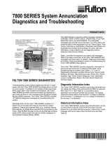
• Mounting: R7910A and R7911 models are mounted
with four number 8 screws. See the screw mounting
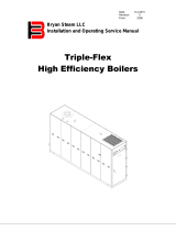
template (Fig. 1). Exception: Models R7910A1118
and R7910A1138 are snap-in mounting. See the
snap-in mounting template (Fig. 2).
SPECIFICATIONS
SEE MODEL LIST IN THE PRODUCT DATA MANUAL
FOR SPECIFIC SPECIFICATIONS.
Electrical ratings:
120 Vac, 15%/+10% (102 to 132 Vac)
24 Vac, 16.6%/+25% (20 to 30 Vac)
Line frequency: Configurable 50 Hz, 60 Hz or both, +/- 5%
(47.5 to 52.5 Hz or 57 to 63 Hz).
Corrosion:
R7910 and R7911 should not be used in a corrosive envi-
ronment. The devices meet NEMA 1 standards.
Operating Temperature: -4 to 150 °F (-20 to 66 °C)
Storage/Shipping Temperature:
-40 to 150 °F (-40 to 66 °C).
Humidity:
85% relative humidity, non-condensing. Condensing
moisture may cause safety shutdown.

R7910A SOLA (HYDRONIC CONTROL) AND R7911 SOLA (STEAM CONTROL) SYSTEMS
66-1174—13 2
Approvals:
Underwriters Laboratories (RU)(cRU):
File No. MP268 (MCCZ2, MCCZ8).
CSD-1 Acceptable.
Meets CSD-1 section CF-300 requirements as a Primary
Safety Control.
Meets CSD-1 section CW-400 requirements as a Tem-
perature Operation Control when configured for use
with 10k Ohm dual element NTC sensors. (R7910 Sola
Hydronic Control.)
Meets CSD-1 section CW-400 requirements as a Temperature
High Limit Control when configured for use with 10k
Ohm dual NTC sensors (R7910 Sola Hydronic Control).
Federal Communications Commission, Part 15,
Class B. Emissions.
INSTALLATION
When Installing This Product…
1. Read these instructions carefully. Failure to follow
them could damage the product or cause a hazard-
ous condition.
2. Refer to the installation manual and wiring diagram
provided as part of the appliance or refer to Product
Data manual, form 66-1171 for R7910 and R7911.
3. Check the ratings given in the instructions and on
the product to make sure that the product is suitable
for your application.
4. Installer must be a trained, experienced combustion
service technician.
5. Disconnect the power supply before beginning
installation to prevent electrical shock and equip-
ment damage. More than one disconnect may be
involved.
6. All wiring must comply with applicable local electri-
cal codes, ordinances and regulations.
7. After installation is complete, check out product
operation as provided in the System Checkout sec-
tion.
WARNING
Fire or Explosion Hazard. Can cause severe
injury, death, or property damage.
To prevent possible hazardous burner operation,
verify safety requirements each time a controller is
installed on a burner.
WIRING
WARNING
Electrical Shock Hazard. Can cause serious
injury, death or property damage.
Disconnect power supply before beginning wiring
to prevent electrical shock and equipment damage.
More than one disconnect may be involved.
Ground Connection
The ground connection on a R7910 or R7911 controller
must not be used as a common ground connection for the
120 Vac connections.
1. Install a common ground terminal next to the R7910
or R7911 controller, close to connector J4 terminal
12.
2. Connect the connector J4 terminal 12 of the R7910
or R7911 controller to the common ground terminal.
3. Connect the ground wires of the main power con-
nector, pumps, and other system components to the
common ground terminal.
Electrical Connections
1. Refer to Product Data Manual 66-1171 for details.
2. Use 18 AWG or larger wires.
3. Wire according to specifications, following all local
ordinances and requirements.
4. L1 input (J4 terminal 8) connect L1 (hot) through
the boiler master switch to energize the L1 input
terminal (J4 terminal 8) on both the 24 Vac and
120 Vac models. Note that this L1 input is not used
as a power source for the Sola controller but as part
of the filtering circuit to protect the Sola controller
from electrical line transients and other electrical
noise.
Device Power Supply, 24 Vac
1. 24 Vac Supply to connector J8 terminal 1.
2. 24 Vac Return to connector J8 terminal 2.
3. Ground to common ground terminal, not to Ground
on J4 terminal 12.
Limit String and Annunciator Inputs and
Safety Load Outputs
1. SOLA wiring to connectors J4, J5, J6 and J7.
2. Line voltage (120 Vac) or low voltage (24 Vac) by
model number.
Dry Contacts available for:
1. Pump A: Connector J4 terminals 6 & 7.
2. Pump B: Connector J4 terminals 4 & 5.
3. Pump C: Connector J4 terminals 2 & 3.
4. Blower: Connector J5 terminals 6 & 7.
5. Alarm: Connector J6 terminals 7 & 8.

R7910A SOLA (HYDRONIC CONTROL) AND R7911 SOLA (STEAM CONTROL) SYSTEMS
366-1174—13
SOLA Wiring Connectors J2, J8, J9,
and J10 Low Voltage Connections
(includes NTC Sensors, 4-20 mA
input[s], PWM Combustion Blower
Motor, Remote and TOD reset,
current and voltage outputs)
1. Wire according to specifications, following all local
ordinances and requirements.
2. Do not bundle the low voltage wires with the ignition
cable or 120 Vac wires.
3. Bundle the wires for the fan and join them with the
other 24V low-voltage wires.
4. Bundle the wires for the NTC sensors and the PWM
pump control separately.
High Voltage Cable
1. Always use a grommet when placing the high volt-
age cable through a sheet metal panel.
2. Never bundle the high voltage cable with other wires.
Communications: Connector J3
1. Connect the S7910A display only to the ECOM port,
connector J3, terminals 1, 2, and 3. Do not connect
the S7999B,C or S7999D display to these connec-
tors.
2. Connect the S7999B,C, D display to connector J3
ModBus, terminals MB1, or MB2 a, b, c terminals.
Flame Signal: Connector J1
1. Flame Rod: Single Element
a. Connect the flame rod for both ignition spark
and flame sense to the ignition transformer ter-
minal.
b. Install a jumper wire between connector J1, ter-
minals 1 and 2.
c. Connect the flame rod ground to connector J1
terminal 3.
2. Flame Rod: Dual Element (separate elements for
ignition spark and flame sense)
a. Connect the flame rod sense lead to connector
J1 terminal 2.
b. Connect the flame rod ground to connector J1
terminal 3.
c. Do not route the flame rod sense lead wire or
ground wire near the ignition spark high-voltage
cable or other line voltage wiring.
UV Flame Detection
1. Connect the UV Flame detector sense lead (blue
wire) to connector J1 terminal 4.
2. Connect the UV Flame detector ground lead (white
wire) to connector J1 terminal 6.
3. Do not route the UV Flame detector wiring near the
ignition spark high-voltage cable or other line volt-
age wiring.
SYSTEM CHECKOUT
This section provides general checkout and
troubleshooting procedures for the Primary Safety
function of R7910 and R7911 Sola devices.
WARNING
Explosion Hazard.
Can cause serious injury or death.
Do not allow fuel to accumulate in the combustion
chamber for longer than a few seconds without
igniting, to prevent danger of forming explosive
mixture. Close manual fuel shutoff valve(s) if flame
is not burning at end of specified time.
WARNING
Electric Shock Hazard.
Can cause serious injury or death.
Use extreme care while testing system. Line
voltage is present on most terminal connections
when power is on.
Open master switch before removing or installing the
R7910 or R7911 Sola device or Display Module connector.
Make sure all manual fuel shutoff valves are closed before
starting initial lightoff check and Pilot Turndown tests.
Do not put the system in service until you have
satisfactorily completed all applicable tests in this section
and any others recommended by the original equipment
manufacturer.
Limit trial for pilot to 10 seconds. Limit the attempt to light
main burner to 2 seconds after the fuel reaches burner
nozzle. Do not exceed manufacturer’s nominal lightoff
time.
CAUTION
Equipment Malfunction or Damage Hazard.
Each device type is unique. Using existing wiring
on a module change can cause equipment
damage. Make wiring changes when a module is
replaced with a different R7910 or R7911 Sola
device to sequence burner.
IMPORTANT
1. If the system fails to perform properly, note the
fault code, fault message, equipment status, and
sequence time on the display. Then refer to the
Fault Code section in the R7910 and R7911
Product Data Manual form 66-1171.
2. Repeat all required Checkout tests after all adjust-
ments are made. All tests must be satisfied with
the flame detector(s) in their final position.
Equipment Recommended
• S7999 Operator Interface Module.
• Volt-ohmmeter (1M ohm/volt minimum sensitivity)
with: 0-300 Vac capability. 0-6000 ohm capability.
0-10 Vdc capability.

R7910A SOLA (HYDRONIC CONTROL) AND R7911 SOLA (STEAM CONTROL) SYSTEMS
66-1174—13 4
Checkout Summary
Table 1 provides an overview of checkout steps performed
for each applicable system.
See the product data manual for location of component
parts terminal locations.
Table 1. Checkout steps and applicable systems.
Preliminary Inspection
Perform the following inspections to avoid common
problems. Make certain that:
1. Wiring connections are correct and all screws are
tight.
2. Flame detector(s) is clean, installed and positioned
properly. Consult the applicable Instructions.
3. Combination connector J1 wiring and flame
detector(s) are correctly used. See product data
manual for wiring.
4. Burner is completely installed and ready to fire;
consult equipment manufacturer’s instructions.
Fuel lines are purged of air.
5. Combustion chamber and flues are clear of fuel and
fuel vapor.
6. Power is connected to the system disconnect switch
(master switch).
7. Lockout is reset (reset button) only if the R7910 or
R7911 Sola Module is powered.
8. System is in STANDBY condition. STANDBY message
Checkout Step
Piloted
Systems
DSI
Systems
Flame
Rod
Systems
Ultraviole
t Flame
Detectors
Preliminary Inspection X X X X
Flame Signal
Measurement
XXX X
Initial Lightoff Check
for Proved Pilot
X
Initial Lightoff Check
for Direct Spark
Ignition
X
Pilot Turndown Test X
Ignition Interference
Test
X
Hot Refractory Hold-
in Test
X
Ignition Spark Pickup X
Response to Other
Ultraviolet Sources
X
Flame Signal with Hot
Combustion Chamber
XXX X
Safety Shutdown Tests X X X X
Checkout Step
Piloted
Systems
DSI
Systems
Flame
Rod
Systems
Ultraviole
t Flame
Detectors

R7910A SOLA (HYDRONIC CONTROL) AND R7911 SOLA (STEAM CONTROL) SYSTEMS
566-1174—13
INITIAL LIGHTOFF CHECKS
Proved Pilot Systems
Perform this check on all installations that use a pilot. It
should immediately follow the preliminary inspection.
NOTE: Low fuel pressure limits, if used, could be open. If
so, bypass them with jumpers during this check.
1. Open the master switch.
2. Make sure that the manual main fuel shutoff valve(s)
is closed. Open the manual pilot shutoff valve. If the
pilot takeoff is downstream from the manual main
fuel shutoff valve(s), slightly open the manual main
valve to supply pilot gas flow. Make sure the main
fuel is shut off just upstream from the burner inlet,
or disconnect power from the automatic main fuel
valve(s).
3. Close the master switch and start the system with a
call for heat by raising the setpoint of the operating
controller; see the R7910 and R7911 Sola Module
sequence. The R7910 or R7911 Sola Module should
start the INITIATE sequence.
4. Let the sequence advance to PILOT IGN (status is
displayed on the S7999 Operator Interface Module,
if used). The PILOT valve energizes, ignition spark
should occur, and the pilot flame should light. If the
pilot ignites, the FLAME LED is energized. Go to step
7.
5. If the pilot flame is not established during the PFEP
(pilot flame establishing period), safety shutdown
occurs. Let the sequence complete its cycle.
6. Push the reset pushbutton and let the system
recycle once. If the pilot flame still does not ignite,
make the following ignition/pilot adjustments:
EXTERNAL IGNITION SOURCE
a. Open the master switch and remove the R7910
and R7911 Sola Module connector J5.
b. Ensure that both the manual pilot shutoff valve
and the manual main shutoff valves are closed.
c. On connector J5, jumper power to the ignition
terminal J5 terminal 4. Disconnect the leadwire
to the pilot valve if it is connected to the same
terminal.
d. Close the master switch to energize only the
ignition transformer.
e. If the ignition spark is not strong and continuous,
open the master switch and adjust the ignition
electrode spark gap setting to the
manufacturer’s recommendation.
f. Make sure the ignition electrodes are clean.
g. Close the master switch and observe the spark.
h. After a continuous spark is obtained, open the
master switch and add a jumper on the
Connector J5 terminal 2 or reconnect the pilot
valve lead wire if it was disconnected in step b.
i. Open the manual pilot shutoff valve.
j. Close the master switch to energize both the
ignition transformer and the pilot valve.
k. If the pilot flame does not ignite and if the igni-
tion spark is still continuous, adjust the pilot gas
pressure regulator until a pilot flame is estab-
lished.
l. When the pilot flame ignites properly and stays
ignited, open the master switch and remove the
jumper(s) from the J5 terminals.
m. Check for adequate bleeding of the fuel line.
n. Reinstall the J5 connector onto the R7910 or
R7911 Sola Module, close the master switch and
return to step 4.
INTERNAL IGNITION SOURCE
To check the internal ignition, the R7910 or R7911
controller will need to be cycled:
a. Open the master switch and remove connector
J5.
b. Ensure both the manual pilot shutoff valve and
the manual main fuel shutoff valves are closed.
c. Cycle the
R7910 or R7911
controller and observe
the ignition spark. (To provide a longer ignition
period, additional time can be added to the pre-
ignition time parameter.)
d. If the ignition spark is not strong and continuous,
open the master switch and adjust the ignition
electrodes spark gap setting to the
manufacturer’s recommendation
e. Make sure that the ignition electrodes are clean.
f. Close the master switch and cycle the
R7910 or
R7911 controller and observe the spark.
g. After obtaining a strong spark, open the master
switch, remove the main valve wire from
connector J5 terminal 3 and re-install connector
J5 to the
R7910 or R7911 controller.
h. Open the manual pilot shutoff valve.
i. Close the master switch and change the pre-
ignition time parameter back to the original
value if you changed it in step C.
j. Cycle the
R7910 or R7911 controller to energize
both the ignition transformer and the pilot valve.
k. If the pilot flame does not ignite and if the
ignition spark is still continuous, adjust the pilot
gas pressure regulator until a pilot flame is
established.
l. When the pilot flame ignites properly and stays
ignited, open the master switch and reconnect
the main valve to the connector J5 terminal 3 (if
removed in step g).
m. Close the master switch and return to Step 4.
7. When the pilot flame ignites, measure the flame
signal. If the pilot flame signal is unsteady or
approaching the flame threshold value (see flame
threshold parameter), adjust the pilot flame size
or detector sighting to provide a maximum and
steady flame signal.
8. Recycle the system to recheck lightoff and pilot
flame signal.
9. When the MAIN Valve energizes, make sure the
automatic main fuel valve is open; then smoothly
open the manual main fuel shutoff valve(s) and
watch for main burner flame ignition. When the main
burner flame is established, go to step 16.
10. If the main burner flame is not established within 5
seconds or the normal lightoff time specified by the
equipment manufacturer, close the manual main
fuel shutoff valve(s).
11. Recycle the system to recheck the lightoff and pilot
flame signal.

R7910A SOLA (HYDRONIC CONTROL) AND R7911 SOLA (STEAM CONTROL) SYSTEMS
66-1174—13 6
12. Smoothly open the manual fuel shutoff valve(s) and
try lightoff again. (The first attempt may have been
required to purge the lines and bring sufficient fuel
to the burner.)
13. If the main burner flame is not established within 5
seconds or the normal lightoff time specified by the
equipment manufacturer, close the manual main
fuel shutoff valve(s). Check all burner adjustments.
14. If the main burner flame is not established after two
attempts:
a. Check for improper pilot flame size.
b. Check for excess combustion air at low fire.
c. Check for adequate low fire fuel flow.
d. Check for proper gas supply pressure.
e. Check for proper valve operation.
f. Check for proper pilot flame positioning.
15. Repeat steps 8 and 9 to establish the main burner
flame; then go to step 16.
16. With the sequence in RUN, make burner adjust-
ments for flame stability and Btu input rating.
17. Shut down the system by opening the burner switch
or by lowering the setpoint of the operating control-
ler. Make sure the main flame goes out. There may
be a delay due to gas trapped between the valve(s)
and burner. Make sure all automatic fuel valve(s)
close.
18. Restart the system by closing the burner switch
and/or raising the setpoint of the operating control-
ler. Observe that the pilot flame is established during
PILOT IGN and the main burner flame is established
during MAIN IGN within the normal lightoff time.
19. Measure the flame signal. Continue to check for the
proper flame signal through the RUN period. Check
the flame signal at both High and Low Firing Rate
positions and while modulating, if applicable.
20. Run the burner through another sequence, observ-
ing the flame signal for:
a. Pilot flame alone.
b. Pilot and main flame together.
c. Main flame alone (unless monitoring an inter-
mittent pilot). Also observe the time it takes to
light the main flame. Ignition of main flame
should be smooth.
21. Make sure all readings are in the required ranges
before proceeding.
22. Return the system to normal operation.
NOTE: After completing these tests, open the master
switch and remove all test jumpers from the con-
nector terminals, limits/controls or switches.
Direct Burner Ignition (DBI)
Systems
This check applies to gas and oil burners not using a pilot.
It should immediately follow the preliminary inspection.
Refer to the appropriate sample block diagram of field
wiring for the ignition transformer and fuel valve(s)
hookup.
NOTE: Low fuel pressure limits, if used, could be open. If
so, bypass them with jumpers during this check.
1. Open the master switch.
2. Complete the normal ready-to-fire checkout of the
fuel supply and equipment as recommended by the
equipment manufacturer.
3. Close all manual main fuel shutoff valve(s). Check
that the automatic fuel valve(s) is closed. Make sure
fuel is not entering the combustion chamber.
4. Close the master switch and start the system with a
call for heat by raising the setpoint of the operating
controller; see R7910 and R7911 Sola Module
sequencing. The program sequence should start the
INITIATE sequence.
5. Let the sequence advance through PREPURGE (if
applicable). Ignition spark should turn on during the
ignition trial period. Listen for the click of the fuel
solenoid valve(s). The R7910 or R7911 Sola Module
locks out and the ALARM LED turns on.
6. Let the R7910 or R7911Sola Module complete its
cycle.
7. Open the manual fuel shutoff valve(s).
8. Push the reset button and the module recycles the
program sequence through PREPURGE (if applica-
ble).
9. When the fuel valve turns on during the ignition
period, make sure that the main burner flame is
established. If it is, go to step 14.
10. If the main burner flame is not established within 4
seconds or within the normal lightoff time specified
by the equipment manufacturer, close the manual
fuel shutoff valve(s), and open the master switch.
11. Wait about three minutes. Close the master switch,
open the manual fuel shutoff valve(s), and try to
lightoff the burner again. The first attempt may be
required to purge the lines and bring sufficient fuel
to the burner. If it is not established on the second
attempt, proceed to step 13.
12. Check all burner adjustments.
13. Make the following ignition and main burner
adjustments:

R7910A SOLA (HYDRONIC CONTROL) AND R7911 SOLA (STEAM CONTROL) SYSTEMS
766-1174—13
INTERNAL IGNITION SOURCE
To check the internal ignition, the R7910 or R7911 con-
troller will need to be cycled:
a. Open the master switch and remove connector
J5.
b. Ensure both the manual main valve shutoff valve
and the manual main fuel shutoff valves are
closed.
c. Cycle the
R7910 or R7911
controller and oberve
the ignition spark. (To provide a longer ignition
period, additional time can be added to the pre-
ignition time parameter.)
d. If the ignition spark is not strong and continuous,
open the master switch and adjust the ignition
electrodes spark gap setting to the manufac-
turer’s recommendation.
e. Make sure the ignition electrodes are clean.
f. Close the master switch and cycle the
R7910 or
R7911 controller and observe the spark.
g. After obtaining a strong spark, open the master
switch, re-install connector J5 to the
R7910 or
R7911 controller.
h. Open the manual main valve shutoff valve.
i. Close the master switch and change the pre-
ignition time parameter back to the original
value if you changed it in step C.
j. Cycle the
R7910 or R7911 controller to energize
both the ignition transformer and the main fuel
valve.
k. If the main flame does not ignite and if the igni-
tion spark is still continuous, adjust the main
burner gas pressure regulator until a main flame
is established.
l. Check the main flame signal and ensure it is
above the threshold level and within the manu-
facturer’s recommendation.
m. Return to Step 8.
EXTERNAL IGNITION SOURCE
a. Open the master switch and remove the R7910
or R7911 Sola module connector J5.
b. Ensure that the manual main burner fuel shutoff
valve is closed.
c. On connector J5, jumper power to the ignition
terminal, J5 terminal 4.
d. Close the master switch to energize only the igni-
tion source.
e. If the ignition spark is not strong and continuous,
open the master switch and adjust the ignition
electrode spark gap to the manufacturer’s rec-
ommendation.
f. Make sure electrodes are clean.
g. Close the master switch and observe the spark.
h. After obtaining a strong and continuous spark,
open the master switch; remove the jumper
between power and J5 terminal 4. Re-install the
connector J5 to the R7910 or R7911 controller.
i. Open the manual main burner fuel shutoff valve.
j. Close the master switch.
k. Cycle the R7910 or R7911 controller to energize
both the ignition source and the main fuel valve.
l. If the main flame does not ignite and if the igni-
tion spark is still continuous, adjust the main
burner gas pressure regulator until a main flame
is established.
m. Check the main flame signal and insure it is
above the threshold level and within the manu-
facture’s recommendations.
n. Return to step 8.
14. When the main burner flame is established, the
sequence advances to RUN. Make burner adjust-
ments for flame stability and input rating.
15. Shut down the system by opening the burner switch
or by lowering the setpoint of the operating control-
ler. Make sure the burner flame goes out and all
automatic fuel valves close.
16. If used, remove the bypass jumpers from the low fuel
pressure limit.
17. Restart the system by closing the burner switch
and/or raising the setpoint of the operating control-
ler. Observe that the main burner flame is estab-
lished during Main Ignition, within the normal
lightoff time specified by the equipment manufac-
turer.
18. Measure the flame signal. Continue to check for the
proper signal through the RUN period. Check the
signal at both high and low firing rate positions and
while modulating. Any pulsating or unsteady read-
ings require further attention.
19. Make sure all readings are in the required ranges
before proceeding.
NOTE: On completing these tests, open the master
switch and remove all test jumpers, limits/con-
trols or switches.
20. Return the system to normal operation.

R7910A SOLA (HYDRONIC CONTROL) AND R7911 SOLA (STEAM CONTROL) SYSTEMS
66-1174—13 8
PILOT TURNDOWN TEST (ALL
INSTALLATIONS USING A
PILOT)
Perform this check on all installations that use a pilot. The
purpose of this test is to verify that the main burner can be
lit by the smallest pilot flame that can hold in the flame
amplifier and energize the FLAME LED. Clean the flame
detector(s) to make sure that it detects the smallest
acceptable pilot flame.
NOTE: Low fuel pressure limits, if used, could be open. If
so, bypass them with jumpers during this test.
1. Open the master switch.
2. Close the manual main fuel shutoff valve(s).
3. Connect a manometer (or pressure gauge) to mea-
sure pilot gas pressure during the turndown test.
4. Open the manual pilot shutoff valve(s).
5. Close the master switch.
— Go to the S7999 Operator Interface Module.
— Select Diagnostics Test button at the bottom of the
display.
— Select Diagnostics test button at the bottom of this
new screen.
— Select Pilot Test at the bottom of this new screen.
— Select Start Test at the bottom of this screen.
6. Start the system with a call for heat. Raise the set-
point of the operating controller. The R7910 or
R7911 Sola sequence should start, and PREPURGE
(if applicable) should begin. The sequence will hold
in the pilot flame establishing period and the
FLAME LED comes on when the pilot flame ignites.
NOTE: If the sequence does not stop, reset the system
and make sure that you selected the Pilot Test.
7. Turn down the pilot gas pressure very slowly, reading
the manometer (or pressure gauge) as it drops. Stop
instantly when the FLAME LED goes out. Note the
pressure reading. The pilot flame is at the minimum
turndown position. Immediately turn up the pilot
pressure until the FLAME LED comes on again or
the flame signal increases to above the flame
threshold value. (See flame threshold parameter).
NOTE: If there is no flame for 15 seconds in the TEST
position, the R7910 or R7911 Sola Module locks
out.
8. Repeat step 7 to verify the pilot gas pressure reading
at the exact point the FLAME LED light goes out.
9. Increase the pilot gas pressure immediately until the
FLAME LED comes on, and then turn it down slowly
to obtain a pressure reading just above the dropout
point or until the flame signal increases to above the
flame threshold value (See flame threshold parame-
ter).
10.
11. Turn the pilot hold test OFF and allow the
R7910 or R7911 controller to start a burner
cycle. During the Main Flame Establishing Period,
make sure the automatic main fuel valve(s) opens;
then smoothly open the manual main fuel shutoff
valve(s) (or any other manually-opened safety shut-
off valve(s), if used) and watch for main burner igni-
tion. If the lightoff is not rough and the main burner
flame is established, go to step 18.
NOTE: This step requires two people, one to open the
manual valve(s) and one to watch for ignition.
12. If the main burner flame is not established within 5
seconds, or within the normal lightoff time specified
by the equipment manufacturer, close the manual
main fuel shutoff valve(s) and open the master
switch. If the lightoff is rough, the pilot flame size is
too small.
13. Close the master switch and perform another pilot
hold test (see step 5).
14. Increase the pilot flame size by increasing its fuel
flow until a smooth main flame lightoff is accom-
plished.
15. Reposition the flame rod or the flame scanner sight
tube or use orifices until the pilot flame signal volt-
age is in the range of 0.7 Vdc above the flame
threshold value.
16. When the main burner lights reliably with the pilot at
turndown, disconnect the manometer (or pressure
gauge) and turn up the pilot gas flow to that recom-
mended by the equipment manufacturer.
17. If used, remove the bypass jumpers from the termi-
nals, limits/controls, or switches.
18. Run the system through another cycle to check for
normal operation.
19. Return the system to normal operation.
IGNITION INTERFERENCE
TEST (FLAME RODS)
Ignition interference can subtract from (decrease) or add
to (increase) the flame signal. If it decreases the flame
signal enough, it causes a safety shutdown. If it increases
the flame signal, it could cause the FLAME LED to come
on when the true flame signal is below the minimum
acceptable value.
Start the burner and measure the flame signal with both
ignition and pilot (or main burner) on, and then with only
the pilot (or main burner) on. Any significant difference
(greater than 0.5 Vdc) indicates ignition interference.
To Eliminate Ignition Interference
1. Make sure there is enough ground area.
2. Be sure the ignition electrode and the flame rod are
on opposite sides of the ground area.
3. Check for correct spacing on the ignition electrode.
(See manufacturer's recommendation.)
4. Make sure the leadwires from the flame rod and
ignition electrode are not too close together.
5. Replace any deteriorated leadwires.
6. If the problem cannot be eliminated, consider
changing the system to an ultraviolet flame detec-
tion system.

R7910A SOLA (HYDRONIC CONTROL) AND R7911 SOLA (STEAM CONTROL) SYSTEMS
966-1174—13
HOT REFRACTORY HOLD-IN
TEST (ULTRAVIOLET
DETECTORS)
This condition can delay response to flame failure and
also can prevent a system restart if hot refractory is
detected.
The ultraviolet detector can respond to hot refractory
above 2300 F (1371 C).
1. When the maximum refractory temperature is
reached, close all manual fuel shutoff valves, or open
the electrical circuits of all automatic fuel valves.
2. Visually observe when the burner flame or FLAME
LED goes out. If this takes more than 3 seconds, the
detector is sensing hot refractory.
3. Immediately terminate the firing cycle. Lower the
setpoint to the operating controller, or set the Fuel
Selector Switch to OFF. Do not open the master
switch.
NOTE: Some burners continue to purge oil lines between
the valves and nozzles even though the fuel
valves are closed. Terminating the firing cycle
(instead of opening the master switch) allows
purging of the combustion chamber. This reduces
buildup of fuel vapors in the combustion cham-
ber caused by oil line purging.
4. If the detector is sensing hot refractory, correct the
condition by one or more of the following proce-
dures:
a. Add an orifice plate in front of the cell to restrict
the viewing area of the detector.
b. Resight the detector at a cooler, more distant
part of the combustion chamber. Make sure the
detector properly sights the flame.
c. Try lengthening the sight pipe or decreasing the
pipe size (diameter).
For details, refer to the detector Instructions and the
equipment Operating Manual. Continue adjustments until
hot refractory hold-in is eliminated.
IGNITION SPARK RESPONSE
TEST (ULTRAVIOLET
DETECTORS)
Test to make certain that the ignition spark is not
actuating the FLAME LED:
1. Open the master switch.
2. Close the pilot and main burner manual fuel shut-off
valve(s).
3. Close the master switch.
— Go to the S7999 Operator Interface Module.
— Select Diagnostics Test button at the bottom of the
display.
— Select Diagnostics test button at the bottom of this
new screen.
— Select Pilot Test at the bottom of this new screen.
— Select Start Test at the bottom of this screen.
4. Start the system with a call for heat. Raise the set-
point of the operating controller. The R7910 or
R7911 Sola sequence should start and prepurge (if
applicable) should begin. The sequence will hold in
pilot flame establishing period with only the ignition
on. Ignition spark should occur but the flame signal
should not be more than 0.5 Vdc.
5. If the flame signal is higher than 0.5 Vdc and the
FLAME LED does come on, consult the equipment
operating manual and resight the detector farther
out from the spark, or away from possible reflection.
It may be necessary to construct a barrier to block
the ignition spark from the detector view. Continue
adjustments until the flame signal due to ignition
spark is less than 0.5 Vdc.
NOTE: For R7910 or R7911 controllers with software
revision xxxx.2292 or higher, if the above proce-
dures have been attempted and flame signal is
still above 0.5 Vdc, use the following procedure:
FOR DIRECT BURNER IGNITION SYSTEMS
a. Using the S7999 Operator Interface Module,
select the Configure button (lower left corner of
the Status page).
b. Using the left scroll down function, scroll down
to select the System Configuration Parameter
page (you will need to be logged in with a pass-
word).
c. Select Flame Sensor Type parameter.
d. Select UV Power Tube with Spark Interference.
e. Changing the Flame Sensor Type will require
parameter verification.
f. Page back one level (upper right screen corner
back arrow button).
g. Select the Verify button.
h. Select Begin.
i. Follow the prompts on the Operator Interface.
FOR PILOT SYSTEMS
a. Using the S7999 Operator Interface Module,
select the Configure button (lower left corner of
the Status page).
b. Using the left scroll down function, scroll down
to select the System Configuration Parameter
page (you will need to be logged in with a pass-
word).
c. Select Flame Sensor Type parameter.
d. Select UV Power Tube with Spark Interference.
e. Select the Burner Control Ignition Page.
f. Select Ignitor On During parameter.
g. Select 1st half of PFEP.
h. Changing these two parameters will require
parameter verification.
i. Page back one level (upper right screen corner
back arrow button).
j. Select the Verify button.
k. Select Begin.
l. Follow the prompts on the Operator Interface.
Response to Other Ultraviolet
Sources
Some sources of artificial light (such as incandescent or
fluorescent bulbs, and mercury sodium vapor lamps) and
daylight produce small amounts of ultraviolet radiation.
Under certain conditions, an ultraviolet detector responds

R7910A SOLA (HYDRONIC CONTROL) AND R7911 SOLA (STEAM CONTROL) SYSTEMS
66-1174—13 10
to these sources as if it is sensing a flame. To check for
proper detector operation, check the Flame Failure
Response Time (FFRT) and conduct Safety Shutdown
Tests under all operating conditions.
Flame Signal With Hot Combustion
Chamber (All Installations)
1. With all initial start-up tests and burner adjustments
completed, operate the burner until the combustion
chamber is at the maximum expected temperature.
2. Observe the equipment manufacturer’s warm-up
instructions.
3. Recycle the burner under these hot conditions and
measure the flame signal. Check the pilot alone, the
main burner flame alone, and both together (unless
monitoring only the pilot flame when using an inter-
mittent pilot, or only the main burner flame when
using DBI). Check the signal at both High and Low
Firing Rate positions and while modulating, if appli-
cable.
4. Lower the setpoint of the operating controller and
observe the time it takes for the burner flame to go
out. This should be within four seconds FFRT of the
R7910 or R7911 controller (one second for
R7910A1029 and R7910A1217).
5. If the flame signal is too low or unsteady, check the
flame detector temperature. Relocate the detector if
the temperature is too high.
6. If necessary, realign the sighting to obtain the
proper signal and response time.
7. If the response time is still too slow, replace the
R7910 or R7911 controller.
8. If the detector is relocated or resighted, or the R7910
or R7911 controller is replaced, repeat all required
Checkout tests.
SAFETY SHUTDOWN TESTS
(ALL INSTALLATIONS)
Perform these tests at the end of Checkout, after all other
tests are completed. If used, the external alarm should
turn on. Press the RESET pushbutton on the R7910 or
R7911 Sola Module to restart the system.
1. Open a Pre-Ignition Interlock (if PII parameter is
enabled) during the STANDBY or PREPURGE period.
a. *Pre-Ignition ILK* fault is displayed on the Oper-
ator Interface Module.
b. Safety shutdown occurs.
2. Opening a Lockout Interlock during PREPURGE,
PILOT IGN, MAIN IGN or RUN period.
a. *Lockout ILK* fault is displayed on the Operator
Interface Module.
b. Safety shutdown occurs.
3. Detection of flame 240 seconds after entry to
STANDBY from RUN. Detection of flame from 10
seconds up to 30 seconds into PREPURGE time.
a. Simulate a flame to cause the flame signal volt-
age level to rise above the flame threshold value
for 240 seconds after entry to STANDBY from
RUN and also simulate a flame signal for 10 sec-
onds to 30 seconds for PREPURGE.
b. *Flame Detected out of sequence* fault is dis-
played on the Operator Interface Module.
c. Safety shutdown occurs.
4. Failure to ignite pilot or Main Burner (DBI setup).
a. Close pilot and main fuel manual shutoff
valve(s).
b. Cycle burner on.
c. Automatic pilot valve(s) or main valves (DBI)
should be energized but the pilot or main burner
(DBI) cannot ignite.
d. *Ignition Failure* fault is displayed on the Opera-
tor Interface to indicate the fault.
e. Safety shutdown occurs.
5. Failure to ignite main (only interrupted pilot applica-
tion).
a. Open the manual pilot valve(s); leave the main
fuel manual shutoff valve(s) closed.
b. Depress the RESET button.
c. Start the system.
d. The pilot should ignite and the flame signal
should be above the flame threshold value but
the main burner cannot light.
e. The flame signal should drop below the flame
threshold value within the FFRT after the inter-
rupted pilot goes out.
f. *Ignition Failure* fault is displayed on the Opera-
tor Interface Module.
g. Safety shutdown occurs.
6. Loss of flame during RUN.
a. Open the main fuel manual shutoff valve(s) and
open manual pilot shutoff valve(s).
b. Depress the RESET button.
c. Start the system. Start-up should be normal and
the main burner should light normally.
d. After the sequence is in the normal RUN period
for at least 10 seconds with the main burner fir-
ing, close the manual main fuel shutoff valve(s)
to extinguish the main burner flame. (On inter-
mittent pilot applications, also, close the pilot
manual shutoff valve.)
e. The flame signal should drop below the flame
threshold value within the FFRT of the R7910 or
R7911 Sola Module after the main flame and/or
pilot goes out.
f. *Main Flame Fail* fault is displayed on the Oper-
ator Interface Module.
g. Safety shutdown or recycle, then lock out on fail-
ure to light the pilot depending on the configura-
tion the R7910 or R7911 Sola Module.
7. Open a Pre-Ignition Interlock after the first 5
seconds of POSTPURGE.
a. Open the main fuel manual shutoff valve(s) and
open manual pilot shutoff valve(s).
b. Depress the RESET button.
c. *Pre-Ignition ILK* fault is displayed on the Oper-
ator Interface Module.
d. Safety shutdown occurs.

R7910A SOLA (HYDRONIC CONTROL) AND R7911 SOLA (STEAM CONTROL) SYSTEMS
11 66-1174—13
IMPORTANT
If the R7910 or R7911 Sola Module fails to shut
down on any of these tests, take corrective action;
refer to Troubleshooting and the Sola Module
diagnostics and return to the beginning of all
checkout tests.
When all checkout tests are completed, reset all switches
to the original status. Remove any jumpers that you may
have installed for testing.
TROUBLESHOOTING
System Diagnostics
Troubleshooting control system equipment failures is
easier with the R7910 or R7911 Sola Module self-
diagnostics and first-out annunciation. In addition to an
isolated spst alarm relay (audible annunciation), the
R7910 or R7911 Sola Module provides visual
annunciation by displaying a fault code and fault or hold
message at the S7999 Operator Interface Module. The
R7910 and R7911 Sola Modules provide many diagnostic
and alert messages for troubleshooting the system.
Self-diagnostics of the R7910 and R7911 Sola Modules
enables them to detect and annunciate both external and
internal system problems. Fault messages, such as
interlock failures, flame failures and false flame signals
are displayed at the Operator Interface Module and
annunciated at the R7910 or R7911 Sola Module by the
ALARM LED.
The Operator Interface displays a sequence status
message indicating: STANDBY, PURGE, PILOT IGN, MAIN
IGN, RUN and POSTPURGE. The selectable messages also
provide visual indication of current status and historical
status of the equipment such as: Flame Signal, Total
Cycles, Total Hours, Fault History, Diagnostic Information
and Expanded Annunciator terminal status (if used). With
this information, most problems can be diagnosed
without extensive trial and error testing.
Diagnostic Information Lockout and Alert History Data are
available to assist in troubleshooting the Sola Module.
The module provides diagnostic information to aid the
service mechanic in obtaining information when trouble-
shooting the system.
Diagnostic Information Index
The R7910 and R7911 Sola Modules monitor digital and
analog input/output (I/O) terminals and can display the
status of the terminal at the Operator Interface Module.
The display shows the actual status of the terminal. If
voltage is detected at a digital I/O terminal, the LED turns
green next to the terminal energized, but if no voltage is
detected at the terminal, the LED will be red. Actual analog
I/O values are displayed on the operator interface module.
Historical Information Index
The R7910 and R7911 Sola Modules have nonvolatile
memory that allows them to retain historical information
for the fifteen most recent lockouts. Each of the fifteen
lockout files retains the cycle when the fault occurred, the
hour of operation when the fault occurred, a fault code, a
fault message and burner status when the fault occurred.
In addition to the lockout files, the R7910 and R7911 Sola
modules retain fifteen alert files.

R7910A SOLA (HYDRONIC CONTROL) AND R7911 SOLA (STEAM CONTROL) SYSTEMS
66-1174—13 12
SERVICE NOTES:
1. Reset the device module by pressing the RESET
pushbutton on the device or pressing a remote reset
pushbutton wired into connector J10. A power-up
reset causes an electrical reset of the module but
does not reset a lockout condition.
2. Use the connector screw terminals to check input or
output voltage.
Alert and Fault Message information is
shown in the appendix of the R7910 and
R7911 Product Data Manual.

R7910A SOLA (HYDRONIC CONTROL) AND R7911 SOLA (STEAM CONTROL) SYSTEMS
13 66-1174—13

R7910A SOLA (HYDRONIC CONTROL) AND R7911 SOLA (STEAM CONTROL) SYSTEMS
66-1174—13 14
2X 8.650 ± .005
2X 5.300 ± .005
4X #8 TAPTITE SCREW
M36232
Fig. 1. Screw Mounting Template.

R7910A SOLA (HYDRONIC CONTROL) AND R7911 SOLA (STEAM CONTROL) SYSTEMS
15 66-1174—13

R7910A SOLA (HYDRONIC CONTROL) AND R7911 SOLA (STEAM CONTROL) SYSTEMS
For More Information
The Honeywell Thermal Solutions family of products includes
Honeywell Combustion Safety, Eclipse, Exothermics, Hauck,
Kromschröder and Maxon. To learn more about our products,
visit ThermalSolutions.honeywell.com or contact your
Honeywell Sales Engineer.
Honeywell Process Solutions
Honeywell Thermal Solutions (HTS)
1250 West Sam Houston Parkway
South Houston, TX 77042
ThermalSolutions.honeywell
® U.S. Registered Trademark
© 2017 Honeywell International Inc.
66-1174—13 M.S. Rev. 11-17
Printed in United States
2X 6.246 ± .005
2X 4.400 ± .005
4X .786 ± .010
4X .280 ± .010
M36233
Fig. 2. Snap-in Mounting Template for
.04" to .06" Thick Sheet Metal.
/