Honeywell 7800 SERIES RM7800L, M Relay Modules Operating instructions
- Type
- Operating instructions

PRODUCT DATA
32-00120-01
SIL3
Capable
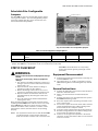
7800 SERIES
RM7800L,M Relay Modules
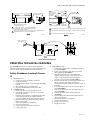
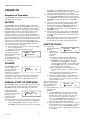
GENERAL
The RM7800 is a microprocessor based integrated burner
control for automatically fired gas, oil, or combination fuel
single burner applications. The RM7800 consists of a
Relay Module and Keyboard Display Module. Subbase,
Amplifier, and Purge Card are required to complete the
system. Options include Personal Computer Interface,
Data ControlBus™ Module*, Remote Display Mounting,
First-Out Expanded Annunciator and Combustion System
Manager™* Software.
The RM7800 is programmed to provide a level of safety,
functional capability and features beyond the capacity of
conventional controls.
Functions provided by the RM7800 include automatic
burner sequencing, flame supervision, system status
indication, system or self-diagnostics and
troubleshooting.
FEATURES
• Safety Features:
— Interlock check.
— Closed loop logic test.
— Dynamic input check.
— Dynamic safety relay test.
— Dynamic self-check logic.
— Expanded safe-start check.
— High Fire Purge Switch test.
— Internal hardware status monitoring.
— Low Fire Start Switch test.
— Tamper resistant timing and logic.
• Access for external electrical voltage checks.
• Application flexibility.
• Communication interface capability.
• Dependable, long-term operation provided by
microcomputer technology.
• First-out annunciation and system diagnostics
provided by a 2 row by 20 column Vacuum
Fluorescent Display (VFD) located on the Keyboard
Display Module.
• First-out expanded annunciation with 26 Light
Emitting Diodes (LEDs) for limits and interlocks
(optional).
Contents
General .................................................................................................... 1
Features .................................................................................................. 1
Specifications ...................................................................................... 2
Principal Technical Features ........................................................ 5
Safety Provisions ................................................................................ 6
Installation ............................................................................................ 8
Assembly ................................................................................................ 16
Operation ............................................................................................... 20
Checkout ................................................................................................ 31
Troubleshooting ................................................................................. 38

7800 SERIES RM7800L,M RELAY MODULES
32-00120-01 2
• Five sequence information Light Emitting
Diodes (LEDs).
• Five function Run/Test Switch.
• Interchangeable plug-in flame amplifiers.
• Local or remote annunciation of operation and
fault information.
• Nonvolatile memory for retaining history files
and sequencing status after loss of power.
• Remote reset (optional).
• Report generation (optional).
• Burner controller data:
— Sequence status.
— Sequence time.
— Hold status.
— Lockout/alarm status.
— Flame signal strength.
— Expanded annunciator status.
— Total cycles of operation.
— Total hours of operation.
— Fault history of six most recent faults:
• Cycles of operation at time of fault.
• Expanded annunciator data at time of fault.
• Fault message and code.
• Hours of operation at time of fault.
• Sequence status at time of fault.
• Sequence time at time of fault.
— Diagnostic information:
• Device type.
• Flame amplifier type.
• Flame failure response time.
• Manufacturing code.
• On/Off status of all digital inputs and outputs.
• Selected prepurge time.
• Software revision and version of RM7800
and Keyboard Display Module.
• Status of configuration jumpers.
• Status of Run/Test Switch.
SPECIFICATIONS
Electrical Ratings:
Voltage and Frequency: 120 Vac (+10/-15%), 50/60 Hz
(±10%).
Keyboard Display Module: 13 Vdc peak full wave rectified
(+20/-15%).
Power Dissipation:
RM7800: 10W maximum.
Display Module: 3W maximum.
Maximum Total Connected Load: 2000 VA.
Fusing: 15A maximum, Type SC or equivalent, fast-blow.
Environmental Ratings:
Ambient Temperature:
Operating: -40°F to +140°F (-40°C to +40°C).
Storage: -40°F to +150°F (-40°C to +66°C).
Humidity: 85% RH continuous, noncondensing.
Vibration: 0.5G environment.
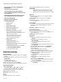
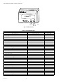
Dimensions: Refer to Figs. 1 and 2.
Weight:
RM7800: 1 pound 13 ounces, unpacked.
Keyboard Display Module: 4 ounces, unpacked.
IMPORTANT:
Flame Detection System available for use with
RM7800. To select your Plug-in Flame Signal
Amplifier and matching Flame Detector, see Table
1.
Approvals:
Underwriters Laboratories Inc. listed, File No. MP268,
guide No. MCCZ.
Factory Mutual approved, Report No. J.I.1V9A0.AF.
IRI acceptable.
Federal Communications Commission, Part 15,
Class B—Emissions.
SIL 3 Capable:
SIL 3 Capable in a properly designed Safety Instrumented
System. See form number 65-0312 for Certificate
Agreement.
Mounting: Q7800A for panel mount.
Required Components:
Plug-in Flame Signal Amplifier, see Table 1.
Plug-in Purge Timer Cards; selectable ST7800A: two sec-
onds to 30 minutes.
Q7800 Universal Wiring Subbase.
Accessories:
Optional:
ControlBus 5-Wire Electrical Connector—part no.
203541.
Combustion System Manager™—part no.
ZM7850A1001.
Communication Interface Base Unit—part no.
Q7700A1014.
Communication Interface ControlBus Module—part no.
QS7800A1001.
Data ControlBus Module™—part no. S7810A1009.
Expanded Annunciator—part no. S7830A1005.
Flame Simulators:
—part no. 203659 UV Flame Simulator.
—part no. 123514A Rectification Simulator.
Remote Display Mounting Bracket—part no. 203765.
Remote Display Power Supply (13 Vdc)—part no.
203968A Plug-In.
Sixty-inch Extension Cable Assembly—part no.
221818A.
120-inch Extension Cable Assembly—part no.
221818C.
Tester—part no. A7800A1002.
Data ControlBus Module™ Multi-Drop Switch Module—
part no. S7810B1007.
Data ControlBus Module™ ModBus Module—part no.
S7810M1008.

7800 SERIES RM7800L,M RELAY MODULES
332-00120-01
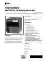
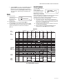
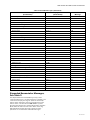
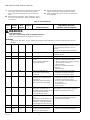
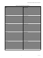
Table 1. Flame Detection Systems (Figs. 3, 4, 5).
aOrder Flame Rod separately; see instructions for the holder.
bThe C7012A,C; C7027, C7035 and C7044 Flame Detectors should be used only on burners that cycle on-off at least once every
twenty-four hours.
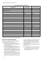
Table 3 provides sequence timing for normal operation.
Table 2. Sequence Timing for Normal Operation.
a STANDBY and RUN can be an infinite time period.
b PURGE will be determined by which ST7800A purge card is selected.
c The MFEP will be determined by which terminal is used, configuration jumper selected or jumper wire added, see Figs. 7, 8 and
25.
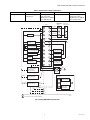
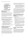
Fig. 1. Mounting dimensions of RM7800 Relay Module and Q7800 Subbase in in. (mm).
Plug-in Flame Signal Amplifiers Applicable Flame Detectors
Type Color
Self-
Checking Model
Flame Failure
Response Time Fuel Type Models
Rectificatio
n
Green No R7847A 3 sec Gas Rectifying Flame
Roda Holder
C7004, C7007, C7011. Complete
Assemblies: C7008, C7009,
Q179.
Gas, oil,
coal
Ultraviolet
(Purple Peeper™) C7012A,C.b
Ultraviolet Purple No R7849A 3 sec Gas, oil Ultraviolet
(Minipeeper™) C7027, C7035, C7044.b
Device Initiate Standby Purge
Flame
Establishing
Period
Run
Post-
Purge
Timing
Interlock
Circuits
Firing
Rate
Circuit
Energy-
Saving
Prepurg
e
Approval
Code
BodiesPilot Mainc
RM7800L 10 sec. ab
4 or 10
sec.
10 or 15
sec.
a15 sec. Preignition
, Lockout,
High and
Low Fire
4-wire
modulatin
g
No FM/IRI
Modulatin
g
RM7800
M
10 sec. 10 sec. or
Intermitten
t
Preignition
, Running,
Low Fire
2-wire
isolated
On-Off-On
contacts
UL/CSA
On/Off
BURNER CONTROL
POWER
PILOT
FLAME
MAIN
ALARM
RESET
SCROLL MODE
SAVE
5
[127]
5 [127]
M3538
5 [133]
1
4
REMOVE ONLY FOR TERMINAL TEST ACCESS.
1
1
R

7800 SERIES RM7800L,M RELAY MODULES
32-00120-01 4
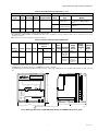
Fig. 2. Mounting dimensions of Keyboard Display Module in in. (mm).
Fig. 3. Rectification detectors.
4 [123]
2
[69]
3
4
M3540
5
32 [4] 29
32
[23]
27
32
SCROLL MODE
SAVE
BURNER CONTROL
1 [32]
1
4
4 [104]
3
32
19
32
[15]
29
32
[23]
7
16
[11] [13]
1
2
2 [62]
7
16
1
[49]
15
16
2
[52]
1
32
5
16 [8]
5
16 [8]
5
32 [4]
3 [99]
7
8
15
32
[12]
13
32
[11]
1 [26]
1
32
R
MOUNTING FLANGE
1/2- 14 NPSM
LEADWIRES FACEPLATE
3/4–14 NPT
M20275A
3-3/4
(95)
7-7/32
(183)
5-1/8 (130)
3-7/16
(87)
5-1/4 (133)
C7012A
THREADED
MOUNTING
HOLES (2)
(10-32 UNF)
1 (25)
FLAME ROD
TARGET
CERAMIC
INSULATORS
IGNITION
ELECTRODE
(Q179C ONLY)
BRACKET
M1983A
3-1/8
(79)
1-21/32
(42) 1-13/32
(36)
3/8 (10)
1/2 (13)
1-1/16
(27)
25/32
(20) 25/32
(20)
2-25/32
(62)
3/32 (2) 11/16
(18)
17/32
(14)

7800 SERIES RM7800L,M RELAY MODULES
532-00120-01
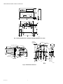
Fig. 4. Ultraviolet detectors.
PRINCIPAL TECHNICAL FEATURES
The RM7800 provides all customary flame safeguard
functions while providing significant advancements in the
areas of safety, annunciation and system diagnostics.
Safety Shutdown (Lockout) Occurs
If:
1. INITIATE Period
a. Purge card is not installed or removed.
b. Purge card is bad.
c. Configuration jumpers were changed (after 200
hours).
d. AC line power errors, see Operation.
e. Four minute INITIATE period is exceeded.
2. STANDBY Period
a. Flame signal is present after 40 seconds.
b. Preignition Interlock is open an accumulative
time of 30 seconds.
c. Interlock check feature is enabled and the Inter-
lock String (including the airflow switch) is
closed for 120 seconds with controller closed.
d. Ignition/pilot valve/intermittent pilot valve ter-
minal is energized.
e. Main valve terminal is energized.
f. Internal system fault.
g. Purge card is not installed or removed.
h. Purge card is bad.
3. PREPURGE Period
a. Preignition Interlock opens anytime during Pre-
purge (RM7800L).
b. Flame signal detected after first ten seconds
during prepurge (RM7800L).
c. High Fire Switch fails to close within four
minutes, fifteen seconds after the firing rate
motor is commanded to drive to high fire
position at start of prepurge (RM7800L).
d. Low Fire Switch fails to close within four minutes,
fifteen seconds after firing rate motor is
commanded to drive to low fire position at end of
prepurge.
e. Running Interlock does not close within 30 sec-
onds (RM7800M).
f. Lockout Interlock does not close within ten sec-
onds (RM7800L).
g. Lockout Interlock opens during prepurge
(RM7800L).
h. Ignition/pilot valve/intermittent pilot valve ter-
minal is energized.
i. Main valve terminal is energized.
j. Internal system fault.
k. Purge card is removed.
l. Purge card is bad.
COLLAR WITH 1/2-14 NPSM
INTERNAL THREADS
4 (102) 8 FOOT (2.44 METER)
LEADWIRES (2)
M1943E
C7027A1064 HAS 24 FOOT (7.32 METER) LEADWIRES.
C7027A1114 HAS 44 IN. (1.118 M) LEADWIRES WITH
22 IN. (558 MM) FLEXIBLE CONDUIT.
MODELS AVAILABLE WITH SPUD CONNECTOR (1/2-14 NPSM INTERNAL
THREADS) INSTEAD OF CLAMP TYPE CONNECTOR.
1
2
2
3-1/2 (89)
1-1/16
(27)
1
1/2-14 NPSM
INTERNAL THREADS
2
2 (51)
COLLAR WITH
1ñ11-1/2 NPSM
INTERNAL
THREADS 1
1DIN APPROVED C7035A1064 HAS 1-11 BSP.P1 INTERNAL MOUNTING THREADS
DIN APPROVED C7035A1064 HAS 1/2-14 BSP-F INTERNAL MOUNTING THREADS
C7035A1056 HAS 12 FOOT (3.66 METER) LEADWIRES.
2
3
INSERTION DEPTH
6 FOOT
[1.83 METER]
LEADWIRES (2) 3
M1945C
2-5/8 (67)
1-1/2
(38)
31/32
(25)
4-1/8 (105)
1-3/16
(30)
MOUNTING BRACKET
6 FOOT [1.83 METER]
LEADWIRES (2)
M1944B
3-5/8 (92)
1/2
(13)
9/16
(14)
7/8
(22)
3/8
(10)
1-27/64
(36)

7800 SERIES RM7800L,M RELAY MODULES
32-00120-01 6
4. PILOT FLAME ESTABLISHING Period (PFEP)
a. Low Fire Switch opens.
b. Lockout Interlock opens (RM7800L).
c. Ignition/pilot valve/intermittent pilot valve ter-
minal is not energized.
d. Early Spark Termination terminal is energized
after five seconds.
e. No flame is present at end of PFEP.
f. Main valve terminal is energized (RM7800M).
g. Internal system fault.
h. Purge card is removed.
i. Purge card is bad.
5. MAIN FLAME ESTABLISHING Period (MFEP)
a. Low Fire Switch opens.
b. Lockout Interlock opens (RM7800L).
c. Ignition/pilot valve/intermittent pilot valve ter-
minal
is not energized.
d. Main valve terminal is not energized.
e. No flame is present at end of MFEP.
f. Internal system fault.
g. Purge card is not installed or removed.
h. Purge card is bad.
6. RUN Period
a. No flame is present.
b. Lockout Interlock opens (RM7800L).
c. Interrupted pilot valve terminal is energized
(RM7800M).
d. Main valve terminal is not energized.
e. Internal system fault.
f. Purge card is not installed or removed.
g. Purge card is bad.
7. POSTPURGE Period
a. Preignition Interlock does not close within five
seconds or opens after five-second time period.
b. Ignition/pilot valve/intermittent pilot valve ter-
minal is energized.
c. Main valve terminal is energized.
d. Internal system fault.
e. Purge card is removed.
f. Purge card is bad.
SAFETY PROVISIONS
Internal Hardware Status
Monitoring
The RM7800 checks the purge card for correct parity to
prevent purge timing shifts and circuitry failures. It also
analyzes the integrity of the configuration jumpers and
internal hardware. The Power LED blinks every four
seconds, signifying an internal hardware check.
Closed Loop Logic Test
The test verifies the integrity of all safety critical loads,
terminals 8, 9, 10 and 21. If the loads are not energized
properly; i.e., the main valve terminal is powered during
prepurge, the RM7800 will lockout on safety shutdown.
The RM7800 must react to input changes but avoid the
occurrence of nuisance shutdown events. Signal
conditioning is applied to line voltage inputs to verify
proper operation in the presence of normal electrical line
noise such as transient high voltage spikes or short
periods of line dropout. Signal conditioning is tolerant of
synchronous noise (line noise events that occur at the
same time during each line cycle).
Dynamic Flame Amplifier and
Shutter Check
Self-checking circuitry tests all electronic components in
the flame detection system and amplifier 10 to 12 times
per minute and shuts down the RM7800 if the detection
system fails.
Dynamic Input Check
All system input circuits are examined to verify the
RM7800 is capable of recognizing the true status of
external controls, limits and interlocks. If any input fails
this test, a safety shutdown occurs and the fault is
annunciated.
Dynamic Safety Relay Test
Checks the ability of the dynamic safety relay contacts to
open and close. It also verifies that the safety critical loads,
terminals 8, 9, 10 and 21, can be de-energized, as
required, by the Dynamic Self-Check logic.
Dynamic Self-Check Safety Circuit
The microcomputer tests itself and related hardware while
at the same time the safety relay system tests the
microcomputer operation. If a microcomputer or safety
relay failure occurs and does not allow proper execution of
the
self-check routine, safety shutdown will occur and all
safety critical loads will be de-energized.
Expanded Safe-Start Check
The conventional safe-start check, which prevents burner
start-up if flame is indicated at start-up, is expanded to
include a flame signal check during STANDBY, a
preignition interlock check, an interlock check, and a
safety critical load check.
High Fire Purge and Low Fire
Start Switch Tests
High Fire Purge Switch Test (RM7800L) examines the
Purge Position Interlock Switch at the moment the firing
rate motor is commanded to the high fire position. If the
switch is bypassed, welded or otherwise closed
prematurely, the system will automatically add 30 seconds
to allow additional drive time for the firing rate motor to
reach or near the open position before starting the purge
timing; otherwise, purge timing starts when the High Fire
Switch is closed. This switch will also cause a hold (four
minutes, fifteen seconds) condition when the switch is
open before purge or opens during purge. The RM7800L
will lockout and annunciate an alarm if the switch fails to
close within the hold time period.
Low Fire Start Switch Test examines the Low Fire Start
Switch at the moment prepurge is completed. If the switch
is bypassed, welded or otherwise prematurely closed, the

7800 SERIES RM7800L,M RELAY MODULES
732-00120-01
system automatically adds 30 seconds to allow the firing
rate motor additional time to reach or near the low fire
start position before ignition trials; otherwise, ignition
trials start after the Low Fire Switch closes. The test also is
used to prove that the firing rate motor is at low fire
position throughout the ignition trial period. This switch
will also cause a hold (four minutes, fifteen seconds)
condition if the switch opens after purging is complete.
The RM7800 will lockout and annunciate an alarm if the
switch fails to close within the hold time period.
Mandatory Purge
If lockout occurs after the initiation of ignition trials, (or at
anytime during a sequence when the fuel valves may have
been energized), a mandatory postpurge period is
imposed.
Off Cycle (Standby or Prepurge)
Flame Signal Check
The flame detection subsystem (flame detector and
amplifier) is monitored during STANDBY. If a flame
simulating condition or an actual flame exists, a system
hold occurs and start-up is prevented. If the flame signal
exists at any time after the first 40 seconds of STANDBY, a
safety shutdown will occur and be annunciated. A shutter-
check amplifier and self-checking detector are energized
for the first 40 seconds during STANDBY and the last two
seconds before exiting STANDBY. If a flame exists, a
safety shutdown occurs.
Preignition Output Circuit Check
At the end of prepurge, the Dynamic Safety Relay
operation is checked. Also, all safety critical loads,
terminals 8, 9, 10 and 21 are checked to verify the
terminals are not powered. If the Dynamic Safety Relay
operation is faulty, or if any of the safety critical loads are
powered, safety shutdown occurs and is annunciated.
Tamper Resistant Timing and Logic
Safety and logic timings are inaccessible and cannot be
altered or defeated.
Verified Spark Termination
The ignition terminal is monitored to verify early spark
termination (five seconds ignition and pilot and five
seconds pilot only).
First-Out Annunciation and
Self-Diagnostics
Sequence Status Lights (LEDs) provide positive visual
indication of the program sequence: POWER, PILOT,
FLAME, MAIN and ALARM. The green POWER LED blinks
every four seconds to signify the RM7800 hardware is
running correctly.
Multi-function Keyboard Display Module shows elapsed
time during prepurge, PILOT IGN, MAIN IGN, and
postpurge. As an additional troubleshooting aid, it
provides sequence timing, diagnostic information,
historical information and expanded annunciator
information when a safety shutdown or hold or normal
operation occurs.
First-out Annunciation reports the cause of a safety
shutdown or identifies the cause of a failure to start or
continue the burner control sequence with an English text
and numbered code via the Keyboard Display Module. It
monitors all field input circuits, including the Flame
Signal Amplifier and Firing Rate Position Switches. The
system distinguishes 127 modes of failure and detects
and annunciates difficult-to-find intermittent failures.
Self-Diagnostics adds to the First-out Annunciation by
allowing the RM7800 to distinguish between field
(external device) and internal (system related) problems.
Faults associated within the flame detection subsystem,
RM7800 or plug-in Purge Card, are isolated and reported
by the Keyboard Display Module, see Troubleshooting
section and 7800 SERIES System Annunciation
Diagnostics and
Troubleshooting, form 65-0118.
Interlock Requirements
The following interlock inputs are provided:
Low Fire Interlock (RM7800 ALL)
This interlock verifies the firing rate motor is in the low fire
position before and during ignition trials.
High Fire Interlock (RM7800L)
This interlock verifies the firing rate motor is in the high
fire position prior to and during PREPURGE. If the High
Fire Switch is jumpered on the RM7800E, the Energy
Saving function will not be performed.
Running Interlock (RM7800M)
This interlock (ILK) input signifies a Running Interlock. If a
Running Interlock is open at the beginning of PREPURGE,
a 30 second hold condition is initiated. If 30 seconds
elapse and the Running Interlock still has not closed, a
lockout will occur. After entering PREPURGE, if the
Running Interlock opens during the first ten seconds, the
purge timer will be reset. This provides a continuous
PURGE to occur without interruption before the Pilot
Flame Establishing Period. If the Running Interlock opens
after 10 seconds into PREPURGE, it will recycle back to
the beginning of PREPURGE. If it opens anytime during
the Ignition Trials or Run, it will proceed to POSTPURGE.
A typical Running Interlock string contains an airflow
switch (see Fig. 7). The Interlock Check is a site
configurable option (see Table 6). If this feature is enabled,
the RM7800 will lockout after 120 seconds, whenever
control terminal 6 is energized, and the Running Interlock
string (including airflow switch) is closed during
STANDBY.
Lockout Interlock (RM7800L)
This interlock (ILK) input signifies a Lockout Interlock. If
the Lockout Interlock is open for more than ten seconds
into PREPURGE, the RM7800L will lockout. After entering
PREPURGE, if the Lockout Interlock opens during the first
ten seconds, the purge timer will be reset. This provides a

7800 SERIES RM7800L,M RELAY MODULES
32-00120-01 8
continuous PURGE to occur without interruption before
the Pilot Flame Establishing Period. If a Lockout Interlock
opens anytime after ten seconds into PURGE, during the
Ignition Trials or Run, it causes a lockout.
A typical Lockout Interlock string contains an airflow
switch (see Fig. 6). The Interlock Check is a site
configurable option (see Table 6). If this feature is enabled,
the RM7800 will lockout after 120 seconds whenever
control terminal 6 is energized, and the Lockout Interlock
string (including airflow switch) is closed during
STANDBY.
Preignition Interlock (RM7800 ALL)
The Preignition Interlock input is typically connected to
proof-of-closure switches for fuel valve(s). The
Preignition Interlock must be energized throughout
PREPURGE. If the Preignition Interlock opens during
STANDBY, it causes a hold (30 seconds). The RM7800 will
lockout if the interlock does not close within 30 seconds
during STANDBY. If the Preignition Interlock opens during
PREPURGE, it will recycle to STANDBY (RM7800M) or will
lockout (RM7800L). If the Preignition Interlock is open
after five seconds into POSTPURGE, the RM7800 will
lockout. The Preignition Interlock is ignored during the
ignition trials state and during RUN.
INSTALLATION
WARNING
Fire or Explosion Hazard.
Can cause property damage, severe injury
or death.
To prevent possible hazardous burner operation,
verification of safety requirememts must be
performed each time a control is installed on a
burner.
When Installing This Product…
1. Read these instructions carefully. Failure to follow
them could damage the product or cause a
hazardous condition.
2. Check the ratings given in the instructions and
marked on the product to make sure the product is
suitable for the application.
3. Installer must be a trained, experienced, flame safe-
guard service technician.
4. After installation is complete, check out the product
operation as provided in these instructions.
CAUTION
Equipment Damage Hazard and Electrical
Shock Hazard.
Can cause property damage and injury.
1. Disconnect the power supply before beginning
installation to prevent electrical shock,
equipment and control damage. More than one
power supply disconnect may be involved.
2. Wiring connections for the RM7800 are unique;
therefore, refer to Fig. 6 through 11 or the
correct Specifications for proper subbase wiring.
3. Wiring must comply with all applicable codes,
ordinances and regulations.
4. Wiring, where required, must comply with NEC
Class 1 (Line Voltage) wiring.
5. Loads connected to the RM7800 must not
exceed those listed on the RM7800 label or the
Specifications, see Table 6.
6. Limits and interlocks must be rated to
simultaneously carry and break current to the
ignition transformer, pilot valve, and main fuel
valve(s).
7. All external timers must be listed or component
recognized by authorities who have jurisdiction
for the specific purpose for which they are used.
IMPORTANT:
1. For on-off gas-fired systems, some authorities
who have jurisdiction prohibit the wiring of any
limit or operating contacts in series between the
flame
safeguard control and the main fuel valve(s).
2. Two Flame Detectors can be connected in parallel.
3. This equipment generates, uses and can radiate
radio frequency energy and, if not installed and
used in accordance with the instructions, may
cause interference to radio communications. It
has been tested and found to comply with the
limits for a Class B computing device of Part 15 of
FCC rules which are designed to provide
reasonable protection against such interference
when operated in a commercial environment.
Operation of this equipment in a residential area
may cause interference; in which case, the users at
their own expense may be required to take
whatever measures are required to correct this
interference.
4. This digital apparatus does not exceed the Class B
limits for radio noise for digital apparatus set out
in the Radio Interference Regulations of the Cana-
dian Department of Communications.
Humidity
Install the RM7800 where the relative humidity never
reaches the saturation point. The RM7800 is designed to
operate in a maximum 85% RH continuous,
noncondensing, moisture environment. Condensing
moisture may cause a safety shutdown.
Vibration
Do not install the RM7800 where it could be subjected to
vibration in excess of 0.5G continuous maximum
vibration.

7800 SERIES RM7800L,M RELAY MODULES
932-00120-01
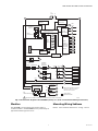
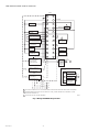
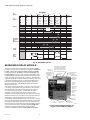
Fig. 5. Internal block diagram of the RM7800L (See Fig. 7, 8, 9, 10 or 11 for detailed wiring instructions).
Weather
The RM7800 is not designed to be weather tight. If
installed outdoors, the RM7800 must be protected by an
approved weather-tight enclosure.
Mounting Wiring Subbase
NOTE: For installation dimensions, see Fig. 1 and 2.
CONFIGURATION
JUMPERS
MICROCOMPUTER
RESET
PUSHBUTTON
RUN/TEST
SWITCH
STATUS LEDs
PLUG-IN PURGE
TIMER CARD
SAFETY RELAY
CIRCUIT
POWER SUPPLY
KEYBOARD
DISPLAY MODULE
HIGH FIRE
COMMON
MODULATE
LOW FIRE
HIGH FIRE SWITCH
PLUG-IN
FLAME
AMPLIFIER
RELAY
DRIVE
CIRCUIT
CONTROL
POWER
TEST
JACK
REMOTE
RESET
DDL
DDL
COMMUNICATIONS
INDICATES FEEDBACK SENSING
OF RELAY CONTACT STATUS
AND LINE VOLT INPUTS
FIELD WIRING
INTERNAL WIRING
IGNITION
PILOT
PILOT/V2
MAIN VALVE
1K
9K
RELAY
STATUS
FEEDBACK
AND LINE
VOLTAGE
INPUTS
LIMITS CONTROLLER
RUNNING/
LOCKOUT
INTERLOCK
PRE-IGNITION
INTERLOCK
1K1 2K1 5K1
8K1
8K2
9K1
9K2
120 Vac
FLAME SIGNAL
TEST
LOW FIRE SWITCH
PROVIDE DISCONNECT MEANS AND OVERLOAD PROTECTION AS REQUIRED.
RS485
123
L1
(HOT) L2
4
6
20
7
4K1
7K1
2K2
10
8
21
9
18
19
8K
7K
6K
5K
4K
3K
2K
F
G
22
1
BLOWER
6K1 5
ALARM
3K1 3
L2
12
13
15
14
M1925A
1

7800 SERIES RM7800L,M RELAY MODULES
32-00120-01 10
1. Mount the subbase in any position except
horizontally with the bifurcated contacts pointing
down. The standard vertical position is
recommended. Any other position decreases the
maximum ambient temperature rating.
2. Select a location on a wall, burner or electrical panel.
The Q7800 can be mounted directly in the control
cabinet. Be sure to allow adequate clearance for ser-
vicing, installation, access or removal of the
RM7800, Expanded Annunciator, Keyboard Display
Module, flame amplifier, flame amplifier signal volt-
age probes, Run/Test Switch, electrical signal volt-
age probes and electrical field connections.
3. For surface mounting, use the back of the subbase
as a template to mark the four screw locations. Drill
the pilot holes.
4. Securely mount the subbase using four no. 6 screws.
WIRING
IMPORTANT
For proper subbase wiring, refer to Fig. 7 or 8.
For proper remote wiring of the Keyboard Display
Module, refer to Fig. 9 through 11 or to the
Specifications for the Keyboard Display Module
(65-0090), Communication Interface Base Unit
(63-2278), Data ControlBus Module™
(65-0091) or Extension Cable Assembly (65-
0131).
NOTE: Part number 203541 5-Wire Connector (order
separately) is required except when using the
extension cable assembly.
WARNING
Electrical Shock Hazard.
Can cause serious injury, death or equipment
damage.
Disconnect the power supply before beginning
installation to prevent electrical shock, equipment
and control damage. More than one power supply
disconnect may be required.
1. For proper remote wiring of the Keyboard Display
Module, refer to the Specifications for the Keyboard
Display Module (65-0090), Network Interface Unit
(63-2278), Data ControlBus Module™ (65-0091) or
Extension Cable Assembly (65-0131).
2. Disconnect the power supply from the main discon-
nect before beginning installation to prevent electri-
cal shock and equipment damage. More than one
disconnect may be required.
3. All wiring must comply with all applicable electrical
codes, ordinances and regulations. Wiring, where
required, must comply with NEC, Class 1 (Line Volt-
age) wiring.
4. Recommended wire size and type: see Table 4.
5. Recommended grounding practices: see Table 5.
6. The Keyboard Display Module, Data ControlBus
Module™ (for remote mounting or communications)
or Communication Interface ControlBus Module
must be wired in a daisy chain configuration, (1(a)-
1(a),
2(b)-2(b), 3(c)-3(c)). The order of interconnection of
all the devices listed above is not important. Be
aware that modules on the closest and farthest end
of the daisy chain configuration string require a 120
ohm (1/4 watt minimum) resistor termination across
terminals 1 and 2 of the electrical connectors, for
connections over
100 feet. Recommended wire routing of leadwires:
a. Do not run high voltage ignition transformer
wires
in the same conduit with the flame detector, Data
Controlbus Module™, or Remote Reset Module
wiring.
b. Do not route flame detector, Data Controlbus
Module™, or Remote Reset Module leadwires in
conduit with line voltage circuits.
c. Enclose flame detector leadwires without armor
cable in metal cable or conduit.
d. Follow directions in flame detector, Data Control-
bus Module™, or Remote Reset Module Instruc-
tions.
7. Keyboard Display Module (KDM): Because the KDM
is powered from a low voltage, energy limited source,
it can be mounted outside of a control panel if it is
protected from mechanical damage.
NOTE: A 13 Vdc power supply must be used any time
more than one Keyboard Display Module is used.
8. Maximum wire lengths follow:
a. RM7800/RM7840 leadwires—The maximum
length of leadwire is 300 feet to terminal inputs
(Control, Preignition Interlock, Running/Lock-
out Interlock, High Fire Switch and Low Fire
Switch).
b. Flame Detector leadwires—The maximum flame
sensor leadwire length is limited by the flame
signal strength.
c. Remote Reset leadwires—The maximum length
of wire is 1000 feet to a Remote Reset pushbut-
ton.
d. Data Controlbus Module™—The maximum Data
Controlbus Module™ cable length depends on
the number of system modules connected, the
noise conditions and the cable used. The maxi-
mum length of all Data Controlbus Module™
interconnecting wire is 1000 feet.
9. Make sure loads do not exceed the terminal ratings.
Refer to the label on the RM7800/RM7840 or to the
ratings in Tables 3, 4 and 5.
Final Wiring Check
1. Check the power supply circuit. The voltage and
frequency tolerance must match those of the
RM7800. A separate power supply circuit may be
required for the RM7800. Add the required
disconnect means and overload protection.
2. Check all wiring circuits and complete the Static
Checkout, see Table 12, before installing the
RM7800 on the subbase.
3. Install all electrical connectors.

7800 SERIES RM7800L,M RELAY MODULES
11 32-00120-01
4. Restore power to the panel.
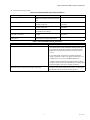
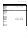
Table 3. Recommended Wire Sizes and Part Numbers.
Table 4. Recommended Grounding Practices.
Application Recommended Wire Size Recommended Part Number(s)
Line voltage terminals 14, 16 or 18 AWG copper conductor,
600 volt insulation, moisture-resistant
wire.
TTW60C, THW75C, THHN90C.
Keyboard Display Module (KDM) 22 AWG two-wire twisted pair with
ground, or five wire.
Belden 8723 shielded cable or
equivalent.
Data ControlBus Module™ 22 AWG two-wire twisted pair with
ground, or five wire.
Belden 8723 shielded cable or
equivalent.
Remote Reset Module 22 AWG two-wire twisted pair,
insulated for low voltage.
—
Communications Interface
ControlBus™ Module
22 AWG two-wire twisted pair with
ground.
Belden 8723 shielded cable or
equivalent.
13 Vdc full-wave rectified transformer
power input.
18 AWG wire insulated for voltages and
temperatures for given application.
TTW60C, THW75C, THHN90C.
Ground Type Recommended Practice
Earth ground (subbase and relay module). 1. Use to provide a connection between the subbase and
the control panel of the equipment. Earth ground must
be capable of conducting enough current to blow the
20A fuse (or breaker) in the event of an internal short
circuit.
2. Use wide straps or brackets to provide minimum
length, maximum surface area ground conductors. If a
leadwire must be used, use 14 AWG copper wire.
3. Make sure that mechanically tightened joints along
the ground path are free of nonconductive coatings and
protected against corrosion on mating surfaces.
Signal ground (KDM, Data ControlBus Module™,
Communications Interface ControlBus™ Module).
Use the shield of the signal wire to ground the device to the
signal ground terminals [3(c)] of each device. Connect the
shield at both ends of the chain to earth ground.

7800 SERIES RM7800L,M RELAY MODULES
32-00120-01 12
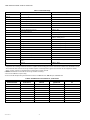
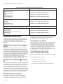
Table 5. Terminal Ratings.
.aThe relay module must have an earth ground providing a connection between the subbase and the control panel or the
equipment. The earth ground wire must be capable of conducting the current to blow the 15A fuse (or breaker) in event
of an internal short circuit. The relay module requires a low impedance ground connection to the equipment frame,
which, in turn, requires a low impedance connection to earth ground.
b2000 VA maximum connected load to relay module assembly.
cCan also be 120 Vac, 1A pilot duty.
dCan also be 65 VA pilot duty with motorized valve, 1150 VA inrush, 460 VA open, 250 VA hold.
Table 6. Combinations for Terminals 8, 9, 10 and 21.
Terminal No. Description Ratings
GFlame Sensor Grounda—
Earth G Earth Grounda—
L2(N) Line Voltage Common —
3 Alarm 120 Vac, 1A pilot duty.
4 Line Voltage Supply (L1) 120 Vac (+10%/-15%), 50 or 60 Hz (±10%).b
5 Burner Motor 120 Vac, 9.8 AFL, 58.8 ALR (inrush).
6 Burner Controller and Limits 120 Vac, 1 mA.
7 Lockout/Running Interlock 120 Vac, 9A.
8 Pilot Valve/Ignition 120 Vac, 4.5A ignition and 50 VA pilot duty.c
9Main Fuel Valve 120 Vac, 2A pilot duty.d
10 Ignition 120 Vac, 4.5A Ignition.c
F(11) Flame Sensor 60 to 220 Vac, current limited.
12 Firing Rate High Fire 120 Vac, 75 VA pilot duty.
13 Firing Rate Common 120 Vac, 75 VA pilot duty.
14 Firing Rate Low Fire 120 Vac, 75 VA pilot duty.
15 Firing Rate Modulate 120 Vac, 75 VA pilot duty.
16 Unused —
17 Unused —
18 Low Fire Switch Input 120 Vac, 1 mA.
19 High Fire Switch Input 120 Vac, 1 mA.
20 Preignition Interlock Input 120 Vac, 1 mA.
21 Interrupted/Intermittent Pilot Valve/First Stage Oil
Valve
120 Vac, 2A pilot duty.
22 Shutter 120 Vac, 0.5A.
Combination No. Pilot Fuel 8 Main 9 Ignition 10
Intermittent Pilot Valve
21
1 C F No Load No Load
2 B F No Load No Load
3 No Load F No Load B
4FFANo Load
5No LoadFAF
6DFANo Load
7No LoadDAD
8 DDA No Load
9No LoadDAD

7800 SERIES RM7800L,M RELAY MODULES
13 32-00120-01
Table 7. Explanation of Each Combination.
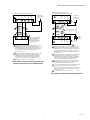
Fig. 6. Wiring RM7800L Relay Module.
ABCD F
4.5A ignition. 50 VA Pilot Duty plus
4.5A ignition.
180 VA ignition plus
motor valve with:
660 VA inrush, 360 VA
open, 260 VA hold.
2A Pilot Duty. 64 VA Pilot Duty plus
motor valves with:
3850 VA inrush, 700 VA
open, 250 VA hold.
M21061
G
L2
3
4
5
6
7
8
9
10
F
(L1)
13
14
15
16
17
18
19
20
21
22
12
LOCKOUT INTERLOCKS
(INC. AIR FLOW SWITCH)
MASTER
SWITCH
LOW FIRE
START SWITCH
5 SECOND IGNITION
(EARLY SPARK
TERMINATION)
MAIN FUEL
VALVE(S)
BURNER
CONTROLLER/LIMITS
BURNER MOTOR
(BLOWER)
HIGH FIRE
COMMON
LOW FIRE
MODULATE
120V ALARM
10 SEC. INTERRUPTED
PILOT/IGNITION
PREIGNITION
INTERLOCK
SERIES 90
FIRING RATE
MOTOR SERIES 90
CONTROLLER
RECTIFYING FLAME
ROD, OR INFRARED
(LEAD SULFIDE)
FLAME DETECTOR
C7027A, C7035A, OR
C7044A ULTRAVIOLET
FLAME DETECTOR
C7012A,C ULTRAVIOLET
FLAME DETECTOR
120V, 50/60 Hz POWER SUPPLY. PROVIDE DISCONNECT MEANS AND OVERLOAD PROTECTION AS REQUIRED.
DO NOT WIRE TO ANY UNUSED TERMINALS.
FOR DIRECT SPARK IGNITION (OIL
OR GAS)
IGNITION
TRANSFORMER
2ND STAGE
FUEL VALVE
(OPTIONAL)
R
W
B
R
W
B
L1
(HOT)
L2 1
OR
OR
BLUE
BLUE
WHITE
YELLOW
L2
WHITE
WHITE
BLACK
BLACK L1
L2
8
9
10
L2
Q7800
2
15 SEC.
INTERRUPTED
PILOT VALVE
2
1
HIGH FIRE
PURGE SWITCH

7800 SERIES RM7800L,M RELAY MODULES
32-00120-01 14
Fig. 7. Wiring RM7800M Relay Module.
M3541B
G
L2
3
4
5
6
7
8
9
10
F
(L1)
13
14
15
16
17
18
19
20
21
22
12
RUNNING INTERLOCKS
(INC. AIR FLOW SWITCH)
MASTER
SWITCH
LOW FIRE
START SWITCH
5 SECOND IGNITION
(EARLY SPARK
TERMINATION)
MAIN FUEL
VALVE(S)
BURNER
CONTROLLER/LIMITS
BURNER MOTOR
(BLOWER)
COMMON
MODULATE
120V ALARM
10 SEC. INTERRUPTED
PILOT/IGNITION
PREIGNITION
INTERLOCK
DAMPER
MOTOR
RECTIFYING FLAME
ROD OR INFRARED
(LEAD SULFIDE)
FLAME DETECTOR
C7027A, C7035A, OR
C7044A ULTRAVIOLET
FLAME DETECTOR
C7012A,C
ULTRAVIOLET
FLAME DETECTOR
120V, 50/60 Hz POWER SUPPLY. PROVIDE DISCONNECT MEANS AND OVERLOAD PROTECTION AS REQUIRED.
WHEN NO DAMPER MOTOR OR LOW FIRE SWITCH IS USED, JUMPER TERMINAL 14 TO TERMINAL 18, AND
DO NOT WIRE TERMINAL 15.
DO NOT WIRE TO ANY UNUSED TERMINALS.
FOR DIRECT SPARK IGNITION (OIL
OR GAS)
IGNITION
TRANSFORMER
2ND STAGE
FUEL VALVE
(OPTIONAL)
L1
(HOT)
L2 1
OR
OR
BLUE
BLUE
WHITE
YELLOW
L2
WHITE
WHITE
BLACK
BLACK L1
L2
21
9
10
L2
1
Q7800
INTERMITTENT
PILOT
1ST STAGE
FUEL VALVE
TO
2
2
2
2
3
3

7800 SERIES RM7800L,M RELAY MODULES
15 32-00120-01
Fig. 8. Wiring the Keyboard Display Module with
Communication Interface ControlBus Module.
Fig. 9. Wiring multiple Keyboard Display Modules.
1
1
120 OHM
RESISTOR
1
120 OHM
RESISTOR
A
B
A
B
CC (GND)
+13 VDC
RESET
123 45
123
MOMENTARY
PUSH BUTTON
SWITCH
S7800 KEYBOARD DISPLAY MODULE
(MOUNTED ON 7800 SERIES RELAY MODULE)
QS7800 COMMUNICATIONS
INTERFACE CONTROLBUS
MODULE, MOUNTED IN
Q7700 COMMUNICATIONS
INTERFACE MODULE
THREE WIRE SHIELDED CABLE MAY BE REQUIRED. TWO 120
OHM TERMINATING RESISTORS ARE REQUIRED FOR
CONNECTIONS OVER 100 FEET (30 METERS). CABLE SHIELD
MUST BE TERMINATED TO EARTH GROUND AT BOTH ENDS.
IF SHIELDED CABLE IS NOT USED, TWISTED PAIR
WIRE MUST BE USED.
WHEN CONNECTING THE KEYBOARD DISPLAY MODULE, DATA
CONTROLBUS MODULE“, OR REMOTE RESET MODULE
EXTERNAL FROM THE CONTROL CABINET, APPROPRIATE
MEASURES MUST BE TAKEN TO MEET EN60730 SAFETY
LOW VOLTAGE REQUIREMENTS (SEE APPROVALS).
M1990F
2
2
3TERMINALS OF 203541 5-WIRE CONNECTOR.
3
L1
(HOT)
L2
1
2
A
B
C (GND)
+13 VDC
RESET
123 54
13 Vdc
POWER
SUPPLY
THREE WIRE SHIELDED CABLE MAY BE REQUIRED. TWO
120 OHM TERMINATING RESISTORS ARE REQUIRED FOR
CONNECTING OVER 100 FEET [30 METERS]. CABLE SHIELD
MUST BE TERMINATED TO EARTH GROUND AT BOTH ENDS.
IF SHIELDED CABLE IS NOT USED, TWISTED PAIR WIRE
MUST BE USED.
WHEN CONNECTING THE KEYBOARD DISPLAY MODULE DATA
CONTROLBUS MODULE“, OR REMOTE RESET MODULE
EXTERNAL FROM THE CONTROL CABINET, APPROPRIATE
MEASURES MUST BE TAKEN TO MEET EN60730 SAFETY
LOW VOLTAGE REQUIREMENTS (SEE APPROVALS).
7800 SERIES RELAY MODULE CAN SUPPORT ONE S7800
KEYBOARD DISPLAY MODULE. A 13 Vdc POWER SUPPLY
IS REQUIRED FOR EACH ADDITIONAL DISPLAY.
UP TO 36 S7800 KEYBOARD DISPLAYS CAN BE CONNECTED
TO A SINGLE 7800 RELAY MODULE NOT TO EXCEED
4000 FEET (1219M) TOTAL LEADWIRE RUN. DAISY CHAIN 1 TO 1,
2 TO 2, 3 TO 3 AND PROVIDE 13 Vdc POWER SUPPLY FOR
EACH S7800 DISPLAY.
M5006G
123 54
A
B
1
S7800 KEYBOARD DISPLAY MODULE
(MOUNTED ON 7800 SERIES RELAY MODULE)
MOMENTARY
PUSHBUTTON
SWITCH
1
S7800 REMOTE KEYBOARD DISPLAY MODULE
2
3
4
3
4
2
C (GND)
+13 VDC
RESET
120 OHM
RESISTOR
120 OHM
RESISTOR
5TERMINALS OF 203541 5-WIRE CONNECTOR.
5
5

7800 SERIES RM7800L,M RELAY MODULES
32-00120-01 16
Fig. 10. Wiring the Data ControlBus Module™
with Remote Keyboard Display.
ASSEMBLY
Mounting RM7800
NOTE: For installation dimensions, see Fig. 1 .
Relay Module Mounting
1. Mount the RM7800 vertically, see Fig. 11 or mount
horizontally with the knife blade terminals pointing
downward. When mounted on the Q7800A, the
RM7800 must be in an electrical enclosure.
2. Select the location in the electrical enclosure. Be
sure to allow adequate clearance for servicing,
installation and removal of the RM7800, Keyboard
Display Module, flame amplifier, flame amplifier
signal voltage probes, electrical signal voltage
probes, and electrical connections.
a. Allow an additional two inches below the
RM7800 for the flame amplifier mounting.
b. Allow an optional three-inch minimum to both
sides of the RM7800 for electrical signal voltage
probes.
3. Make sure no subbase wiring is projecting beyond
the terminal blocks. Tuck wiring in against the back
of the subbase so it does not interfere with the knife
blade terminals or bifurcated contacts.
IMPORTANT:
The RM7800 must be installed with a plug-in
motion rather than a hinge action.
4. Mount the RM7800 by aligning the four L shaped
corner guides and knife blade terminals with the
bifurcated contacts on the wiring subbase and tight-
ening the two screws securely without deforming the
plastic.
Installing ST7800 Purge Card
1. Remove the Keyboard Display Module, Data
ControlBus Module™ or Extension Cable Assembly,
see Fig. 12.
2. Remove the current ST7800 from the RM7800 by
pulling upward the plastic support cover.
3. Make sure that the ST7800 selected has the desired
timing.
4. Insert the Purge Card into the opening of the
RM7800 compartment, see Fig. 12.
5. Reinstall the Keyboard Display Module or Data
ControlBus Module™ onto the RM7800 and restore
power to the device.
6. Run the burner system through at least one com-
plete cycle to verify the system is operating as
desired.
IMPORTANT:
The RM7800 will not function properly without
one of the following mounted correctly: Keyboard
Display Module, DATA CONTROLBUS MODULE™
or an Extension Cable Assembly.
Fig. 11. Electrical Panel installation.
1
1
120 OHM
RESISTOR
1
120 OHM
RESISTOR
A
B
A
B
C (GND)
+13 VDC
RESET
C (GND)
+13 VDC
RESET
123 45
123 45
MOMENTARY
PUSHBUTTON
SWITCH
S7810 DATA CONTROLBUS™ MODULE
(MOUNTED ON 7800 SERIES RELAY MODULE)
S7800 REMOTE KEYBOARD DISPLAY MODULE
THREE-WIRE SHIELDED CABLE MAY BE REQUIRED. TWO 120
OHM TERMINATING RESISTORS ARE REQUIRED FOR
CONNECTIONS OVER 100 FEET. CABLE SHIELD MUST BE
TERMINATED TO EARTH GROUND AT BOTH ENDS. IF SHIELDED
CABLE IS NOT USED, TWISTED PAIR WIRE MUST BE USED.
WHEN CONNECTING THE KEYBOARD DISPLAY MODULE DATA
CONTROLBUS™ MODULE, OR REMOTE RESET MODULE
EXTERNAL FROM THE CONTROL CABINET, APPROPRIATE
MEASURES MUST BE TAKEN TO MEET EN60730 SAFETY
LOW VOLTAGE REQUIREMENTS (SEE APPROVALS).
M1987E
2
2
3
TERMINALS OF 203541 5-WIRE CONNECTOR SUPPLIED WITH
MOUNTING BRACKET FOR REMOTE MOUNTING OF S7800
KEYBOARD DISPLAY MODULE.
3

7800 SERIES RM7800L,M RELAY MODULES
17 32-00120-01
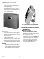
Fig. 12. ST7800 Purge Card installation.
Mounting Keyboard Display Module
1. Align the two interlocking ears of the Keyboard Dis-
play Module with the two mating slots on the
RM7800, see Fig. 13.
2. Insert the two interlocking ears into the two mating
slots and with a hinge action push on the lower cor-
ners of the Keyboard Display Module to secure it to
the RM7800.
3. Verify the Keyboard Display Module is firmly in
place.
Fig. 13. Keyboard Display Module mounting.
Fig. 14. Data ControlBus Module™ mounting.
Fig. 15. Extension Cable Assembly mounting.
Mounting Data ControlBus Module™
and Extension Cable Assembly
1. Align the two interlocking ears with the two mating
slots on the RM7800, See Figs. 14 and 15.
2. Insert the two interlocking ears into the two mating
slots and push on the lower corners of the Data Con-
trolBus Module™ to secure it to the RM7800.
3. Be sure the Data ControlBus Module™ or Extension
Cable Assembly is firmly in place.
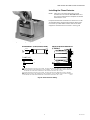
Remote Mounting of Keyboard Display
Module
The Keyboard Display Module can be mounted either on
the face of a panel door or on other remote locations. See
Fig. 16. When mounting the Keyboard Display Module on
the face of a door panel, closely follow these instructions:
1. Select the location on the door panel for flush
mounting.
Pay attention to the insertion dimension of the two
Keyboard Display Module screws, two interlocking

7800 SERIES RM7800L,M RELAY MODULES
32-00120-01 18
ears and the two plug-in connectors to allow for suf-
ficient clearance, 1/4 in. (6 mm) inward from the
surface of the door panel.
2. Use the Keyboard Display Module as a template (see
Fig. 30). Mark the two screw locations, two interlock-
ing ear locations and the two plug-in connector
locations. Drill the pilot holes on the door panel for
the interlocking ears and plug-in connector holes.
3. Mount the Keyboard Display Module, securing the
module with two no. 4 screws.
Fig. 16. Panel mounting of Keyboard Display Module.
When mounting the Keyboard Display Module on a wall or
remote location, use the 203765 Remote Mounting
Bracket. See Fig. 17.
1. Using the Remote Mounting Bracket as a template,
mark the four screw locations and drill the pilot
holes.
2. Mount the remote Mounting Bracket by securing it
with four no. 6 screws.
3. Mount the Keyboard Display Module by aligning the
two interlocking ears with the two mating slots on
the Remote Mounting Bracket.
4. Insert the two interlocking ears into the two mating
slots on the Remote Mounting Bracket.
5. Push on the lower corners of the Keyboard Display
Module to secure it to the Remote Mounting Bracket.
6. Verify that the Keyboard Display Module is firmly in
place.
IMPORTANT
A Keyboard Display Module, Data ControlBus™
Module or Extension Cable Assembly is required
on the Relay Module to remote mount the Key-
board Display Module. Follow wiring diagrams in
Fig. 8, 9 or 10 when using the Keyboard Display
Module or Data ControlBus™ Module.
Fig. 17. Mounting the Keyboard Display Module
on the Remote Mounting Bracket. (203541 5-Wire
Connector provided with Remote Mounting Bracket.)
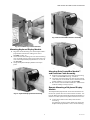
Installing Plug-in Flame Signal Amplifier
WARNING
Electrical Shock Hazard.
Can cause serious injury, death or property
damage.
Disconnect the power supply before beginning
installation of the flame signal amplifier. More than
one disconnect may be involved.
1. Align the flame amplifier circuit board edge connec-
tor with the keyed receptacle on the RM7800. Verify
that the amplifier nameplate faces away from the
Relay Module. See Fig. 18.
2. Push in the amplifier until the circuit board is fully
inserted into the receptacle and then push the
amplifier toward the RM7800 retaining clasp.
3. Verify that the amplifier is firmly in place.
4. Perform all required checkout tests.

7800 SERIES RM7800L,M RELAY MODULES
19 32-00120-01
Fig. 18. Flame signal amplifier mounting.
Installing the Flame Detector
NOTE: Table 2 lists the flame detection systems
available for use with the RM7800. Make sure
the correct combination of amplifier and flame
detector(s) is used.
Proper flame detector installation is the basis of a safe
and reliable flame safeguard installation. Refer to the
instructions packed with the flame detector and the
equipment manufacturer instructions. See Fig. 19.
Fig. 19. Flame detector wiring.
M21060
BLUE
WHITE
F
G
ULTRAVIOLET (C7027/C7035/C7044)
BLUE
YELLOW
BLACK
BLACK
F
G
L1
L2
SOLID STATE ULTRAVIOLET
(C7012A,C)
1
2
G
F
X
X
FLAME ROD
1FLAME DETECTOR LEADS ARE COLOR CODED. THE BLUE LEAD MUST BE CONNECTED TO THE F TERMINAL
AND THE WHITE MUST BE CONNECTED TO THE G TERMINAL. THE UV SENSING TUBE IS POLARITY SENSITIVE.
REVERSING THE LEADS EVEN MOMENTARILY CAN DAMAGE OR DESTROY THE UV TUBE.
FLAME DETECTOR LEADS ARE COLOR CODED. THE BLUE LEAD MUST BE CONNECTED TO THE F TERMINAL
AND THE YELLOW MUST BE CONNECTED TO THE G TERMINAL. THE UV SENSING TUBE IS POLARITY SENSITIVE.
REVERSING THE LEADS EVEN MOMENTARILY CAN DAMAGE OR DESTROY THE UV TUBE.
2

7800 SERIES RM7800L,M RELAY MODULES
32-00120-01 20
OPERATION
Sequence of Operation
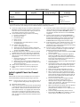
The RM7800 has the following operating sequences, see
Figs. 20 and 21, and Table 3.
INITIATE
The RM7800 enters the INITIATE sequence when the
Relay Module is powered. The RM7800 can also enter the
INITIATE sequence if the Relay Module verifies voltage
fluctuations of +10/-15% or frequency fluctuations of +/-
10% during any part of the operating sequence. The
INITIATE sequence lasts for ten seconds unless the
voltage or frequency tolerances are not met. When the
tolerances are not met, a hold condition will be initiated
and will be displayed on the VFD for at least five seconds.
When the tolerances are met, the INITIATE sequence will
restart. If the condition is not corrected and the hold
condition exists for four minutes, the RM7800 will lockout.
Causes for hold conditions in the INITIATE sequence:
1. AC line dropout is detected.
2. AC line noise that can prevent a sufficient reading of
the line voltage inputs.
3. Brownouts caused by a low line voltage.
The INITIATE sequence
also delays the burner
motor starter from being
energized and
de-energized from an
intermittent AC line input
or control input.
STANDBY
The RM7800 is ready to
start an operating
sequence when the
operating control
determines a call for heat
is present. The burner
switch, limits, operating control and all microcomputer
monitored circuits must be in the correct state for the
RM7800 to continue into the PREPURGE sequence.
NORMAL START-UP PREPURGE
The RM7800 provides a prepurge timing selectable from
two seconds to 30 minutes with power applied and the
RM7800 operating control indicating a call for heat.
Running Interlocks,
Preignition Interlocks,
Burner Switch, Run/Test
Switch, Lockout
Interlocks and all
microcomputer
monitored circuits must be in the correct operating state.
1. The blower motor output, terminal 5, is powered to
start the PREPURGE sequence, except for the
RM7800E. The firing rate motor is driven to the high
fire position. The PREPURGE timing for the
RM7800L does not begin until the Lockout Interlock
String and High Fire Switch are both closed.
2. The Preignition Interlock input must remain closed
throughout PREPURGE; otherwise, control returns
to the STANDBY state and holds (30 seconds) for the
RM7800M or safety shutdown for the RM7800L
occurs.
3. The Lockout Interlock or Running Interlock inputs
(interlock circuit including Airflow Switch) must
close by ten seconds into PREPURGE; otherwise, a
recycle to the beginning of PREPURGE for the
RM7800M will happen or a safety shutdown for the
RM7800L occurs.
4. After the firing rate motor reaches the PREPURGE
rate position and PREPURGE timing is completed,
the firing rate motor will drive to the low fire position,
RM7800L.
5. When the firing rate motor reaches low fire position,
the Low Fire Switch, terminal 18, input must be
energized before entering the Ignition Trial state.
IGNITION TRIALS
1. Pilot Flame
Establishing Period
(PFEP):
a. With the firing
rate motor at
the low fire
position:
(1) The pilot valve and ignition transformer,
terminals 8, 10 and 21, are energized. The
RM7800M has an intermittent pilot valve,
terminal 21. The RM7800L has a fifteen
second interrupted pilot valve, terminal 21. All
the RM7800s have a ten second interrupted
pilot valve/ignition, terminal 8.
(2) During PFEP, the Low Fire Switch must
remain closed. If it opens, a safety shutdown
occurs.
(3) The Preignition Interlock input is ignored
throughout the Ignition Trial state.
b. Flame must be proven by the end of the four or
ten second PFEP to allow the sequence to con-
tinue. If flame is not proven by the end of PFEP, a
safety shutdown occurs.
With flame proven, the
ignition, terminal 10, is
de-energized for early
spark termination.
2. Main Flame Estab-
lishing Period
(MFEP):
a. The RM7800L has a selectable ten second or
fifteen second MFEP. After the Ignition Trials,
and with the presence of flame, the main fuel
valve, terminal 9, is powered. If a flameout
occurs, the RM7800 will lockout within .8 or 3
seconds, depending on the Flame Failure
Response Time (FFRT) of the amplifier.
b. After the Ignition Trials, and with the presence of
flame, the main fuel valve, terminal 9, is powered.
If a flameout occurs, the RM7800 will lockout
within .8 or 3 seconds, depending on the FFRT of
the amplifier.
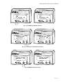
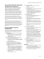
INITIATE 00:10
Diagnostic Info
M20277
STANDBY
Total Cycles 132
M20278
PURGE 00:30
Total Hours 396
M20282
POLIT IGN 00:10
Fault History
M20283
MAIN IGN 00:15
Flame Signal 2.7V
M20284
Page is loading ...
Page is loading ...
Page is loading ...
Page is loading ...
Page is loading ...
Page is loading ...
Page is loading ...
Page is loading ...
Page is loading ...
Page is loading ...
Page is loading ...
Page is loading ...
Page is loading ...
Page is loading ...
Page is loading ...
Page is loading ...
Page is loading ...
Page is loading ...
Page is loading ...
Page is loading ...
-
 1
1
-
 2
2
-
 3
3
-
 4
4
-
 5
5
-
 6
6
-
 7
7
-
 8
8
-
 9
9
-
 10
10
-
 11
11
-
 12
12
-
 13
13
-
 14
14
-
 15
15
-
 16
16
-
 17
17
-
 18
18
-
 19
19
-
 20
20
-
 21
21
-
 22
22
-
 23
23
-
 24
24
-
 25
25
-
 26
26
-
 27
27
-
 28
28
-
 29
29
-
 30
30
-
 31
31
-
 32
32
-
 33
33
-
 34
34
-
 35
35
-
 36
36
-
 37
37
-
 38
38
-
 39
39
-
 40
40


Honeywell 7800 SERIES RM7800L, M Relay Modules Operating instructions
- Type
- Operating instructions
Ask a question and I''ll find the answer in the document
Finding information in a document is now easier with AI
Related papers
-
Honeywell RM7840G User manual
-
-
-
-
-
-
-
-
-
Other documents
-
 Kromschroder Fulton 7800 SERIES System Annunciation Diagnostics and Troubleshooting Operating instructions
-
 2nd Ave. 7800 Series Relay Module User manual
-
Greenheck 7800 series Installation guide
-
 Applied Air GAS-FIRED HEATERS Installation & Operation Instruction
-
A.O. Smith 1700 User manual
-
Weil-McLain 80 Owner's manual
-
Roberts Gordon Air Turnover Unit User manual
-
 Bryan Boilers Triple-Flex 250 User manual
-
Burnham Sage Boiler Control User manual
-


