Page is loading ...

Sony Corporation
Printed in Japan
Professional Disc
Camcorder
Operating Instructions
Before operating the unit, please read this manual
thoroughly and retain it for future reference.
PDW-F330L
PDW-F330K
PDW-F350L
© 2006 Sony Corporation
* I -3-990 -970-14*
(2)
* I -3-990 -970- 14*
(2)
The supplied CD-ROM includes operating instructions for the PDW-F330/F350
Professional Disc Camcorder (English, Japanese, French, German, Italian,
Spanish and Chinese versions) in PDF format.
For more details, see “Using the CD-ROM Manual” on page 9.

2
Owner’s Record
The model and serial numbers are located on the top.
Record these numbers in the spaces provided below. Refer
to them whenever you call upon your Sony dealer
regarding this product.
Model No. Serial No.
To reduce the risk of fire or electric shock,
do not expose this apparatus to rain or
moisture.
To avoid electrical shock, do not open the
cabinet. Refer servicing to qualified
personnel only.
This Professional Disc Camcorder is classified as a CLASS 1
LASER PRODUCT.
Laser diode properties
Wavelength: 403 to 410 nm
Emission duration: Continuous
Laser output power: 65 mW (max. of pulse peak), 35 mW
(max. of CW)
Tekniska data för laserdiod
Våglängd: 403 till 410 nm
Emissionslängd: Kontinuerlig
Laseruteffekt: 65 mW (max. för pulstopp), 35 mW (max. för
kontinuerlig våg)
Spesifikasjoner laserdiode
Bølgelengde: 403 til 410 nm
Strålingens varighet: Kontinuerlig
Laserens effekt: 65 mW (maks stråletoppunkt), 35 mW
(maks ved kontinuerlig stråling)
Laserdiodin ominaisuudet
Aallon pituus: 403 - 410 nm
Välityksen kesto: Jatkuva
Laserlähdön teho: 65 mW (sykehuipun maks.), 35 mW
(jatkuvan aallon maks.)
CAUTION
The use of optical instruments with this product will increase
eye hazard.
CAUTION
Use of controls or adjustments or performance of procedures
other than those specified herein may result in hazardous
radiation exposure.
VAROITUS!
LAITTEEN KÄYTTÄMINEN MUULLA KUIN TÄSSÄ
KÄYTTÖOHJEESSA MAINITULLA TAVALLA SAATTAA
ALTISTAA KÄYTTÄJÄN TURVALLISUUSLUOKAN 1
YLITTÄVÄLLE NÄKYMÄTTÖMÄLLE LASERSÄTEILYLLE.
VARNING
OM APPARATEN ANVÄNDS PÅ ANNAT SÄTT ÄN I DENNA
BRUKSANVISNING SPECIFICERATS, KAN ANVÄNDAREN
UTSÄTTAS FÖR OSYNLIG LASERSTRÅLNING, SOM
ÖVERSKRIDER GRÄNSEN FÖR LASERKLASS 1.
WARNING
This label is located inside
the outside panel of the unit.
Denna etikett finns på
apparatens ovansida.
Denne mærkat sidder på
apparatets øverste panel.
Tämä kyltti sijaitsee laitteen
yläpinnalla.
Dette merket er plassert på
oversiden av produktet.

3
For the customers in the U.S.A.
This equipment has been tested and found to comply with the
limits for a Class A digital device, pursuant to Part 15 of the
FCC Rules. These limits are designed to provide reasonable
protection against harmful interference when the equipment is
operated in a commercial environment. This equipment
generates, uses, and can radiate radio frequency energy and,
if not installed and used in accordance with the instruction
manual, may cause harmful interference to radio
communications. Operation of this equipment in a residential
area is likely to cause harmful interference in which case the
user will be required to correct the interference at his own
expense.
You are cautioned that any changes or modifications not
expressly approved in this manual could void your authority to
operate this equipment.
All interface cables used to connect peripherals must be
shielded in order to comply with the limits for a digital device
pursuant to Subpart B of Part 15 of FCC Rules.
For the customers in the USA and Canada
RECYCLING LITHIUM-ION BATTERIES
For the State of California, USA only
Perchlorate Material - special handling may apply, See
www.dtsc.ca.gov/hazardouswaste/perchlorate
Perchlorate Material : Lithium battery contains perchlorate.
For the customers in Europe
This product with the CE marking complies with the EMC
Directive issued by the Commission of the European
Community.
Compliance with this directive implies conformity to the
following European standards:
• EN55103-1: Electromagnetic Interference (Emission)
• EN55103-2: Electromagnetic Susceptibility (Immunity)
This product is intended for use in the following
Electromagnetic Environment(s):
E1 (residential), E2 (commercial and light industrial), E3
(urban outdoors) and E4 (controlled EMC environment, ex. TV
studio).
The manufacturer of this product is Sony Corporation, 1-7-1
Konan, Minato-ku, Tokyo, Japan.
The Authorized Representative for EMC and product safety is
Sony Deutschland GmbH, Hedelfinger Strasse 61, 70327
Stuttgart, Germany. For any service or guarantee matters
please refer to the addresses given in separate service or
guarantee documents.
For the customers in Taiwan only
Voor de Klanten in Nederland
Lithium-Ion batteries are recyclable.
You can help preserve our environment
by returning your used rechargeable
batteries to the collection and recycling
location nearest you.
For more information regarding recycling of rechargeable
batteries, call toll free 1-800-822-8837, or visit
http://www.rbrc.org/
Caution: Do not handle damaged or leaking lithium-ion
batteries.
• Gooi de batterij niet weg maar lever deze in als
klein chemisch afval (KCA).
• Dit apparaat bevat een vast ingebouwde
batterij die niet vervangen hoeft te worden
tijdens de levensduur van het apparaat.
• Raadpleeg uw leverancier indien de batterij
toch vervangen moet worden.De batterij mag
alleen vervangen worden door vakbekwaam
servicepersoneel.
• Lever het apparaat aan het einde van de
levensduur in voor recycling, de batterij zal dan
op correcte wijze verwerkt worden.

4
Afin de réduire les risques d’incendie ou
d’électrocution, ne pas exposer cet
appareil à la pluie ou à l’humidité.
Afin d’écarter tout risque d’électrocution,
garder le coffret fermé. Ne confier
l’entretien de l’appareil qu’à un personnel
qualifié.
Pour les utilisateurs aux Etats-Unis et au Canada.
RECYCLAGE DES ACCUMULATEURS AUX IONS DE
LITHIUM
Pour les clients européens
Ce produit portant la marque CE est conforme à la Directive
sur la compatibilité électromagnétique (EMC) émise par la
Commission de la Communauté européenne.
La conformité à cette directive implique la conformité aux
normes européennes suivantes
:
EN55103-1 : Interférences électromagnétiques (émission)
EN55103-2 : Sensibilité électromagnétique (immunité)
Ce produit est prévu pour être utilisé dans les environnements
électromagnétiques suivants
:
E1 (résidentiel), E2 (commercial et industrie légère),
E3
(urbain extérieur) et E4 (environnement EMC contrôlé, ex.
studio de télévision).
Le fabricant de ce produit est Sony Corporation, 1-7-1 Konan,
Minato-ku, Tokyo, Japon.
Le représentant autorisé pour EMC et la sécurité des produits
est Sony Deutschland GmbH, Hedelfinger Strasse 61, 70327
Stuttgart, Allemagne. Pour toute question concernant le
service ou la garantie, veuillez consulter les adresses
indiquées dans les documents de service ou de garantie
séparés.
Les accumulateurs aux ions de lithium
sont recyclables.
Vous pouvez contribuer à préserver
l’environnement en rapportant les piles
usées dans un point de collection et
recyclage le plus proche.
Pour plus d’informations sur le recyclage des
accumulateurs, téléphonez au numéro gratuit
1-800-822-8837 (Etats-Unis et Canada uniquement), ou
visitez http://www.rbrc.org/
Avertissment: Ne pas utiliser des accumulateurs aux ions
de lithium qui sont endommagés ou qui fuient.
AVERTISSEMENT
Cette étiquette est placée à
l’intérieur du panneau
extérieur de l’appareil.

5
Um die Gefahr von Bränden oder
elektrischen Schlägen zu verringern, darf
dieses Gerät nicht Regen oder Feuchtigkeit
ausgesetzt werden.
Um einen elektrischen Schlag zu
vermeiden, darf das Gehäuse nicht
geöffnet werden. Überlassen Sie
Wartungsarbeiten stets nur qualifiziertem
Fachpersonal.
Daten der Laserdiode
Wellenlänge: 403 bis 410 nm
Emissionsdauer: Ununterbrochen
Laser-Ausgangsleistung: 65 mW (max. Impulsspitze), 35
mW (max. Dauerstrich)
GEFAHR
Bei geöffnetem Laufwerk und beschädigter oder deaktivierter
Verriegelung tritt ein unsichtbarer Laserstrahl aus.
Direkter Kontark mit dem Laserstrahl ist unbedingt zu
vermeiden.
Für Kunden in Europa
Dieses Produkt besitzt die CE-Kennzeichnung und erfüllt die
EMV-Richtlinie der EG-Kommission.
Angewandte Normen:
• EN55103-1: Elektromagnetische Verträglichkeit
(Störaussendung)
• EN55103-2: Elektromagnetische Verträglichkeit
(Störfestigkeit)
Für die folgenden elektromagnetischen Umgebungen: E1
(Wohnbereich), E2 (kommerzieller und in beschränktem
Maße industrieller Bereich), E3 (Stadtbereich im Freien) und
E4 (kontrollierter EMV-Bereich, z.B. Fernsehstudio).
Der Hersteller dieses Produkts ist Sony Corporation, 1-7-1
Konan, Minato-ku, Tokyo, Japan.
Der autorisierte Repräsentant für EMV und Produktsicherheit
ist Sony Deutschland GmbH, Hedelfinger Strasse 61, 70327
Stuttgart, Deutschland. Bei jeglichen Angelegenheiten in
Bezug auf Kundendienst oder Garantie wenden Sie sich bitte
an die in den separaten Kundendienst- oder
Garantiedokumenten aufgeführten Anschriften.
Für Kunden in Deutschland
Entsorgungshinweis: Bitte werfen Sie nur entladene Batterien
in die Sammelboxen beim Handel oder den Kommunen.
Entladen sind Batterien in der Regel dann, wenn das Gerät
abschaltet und signalisiert “Batterie leer” oder nach längerer
Gebrauchsdauer der Batterien “nicht mehr einwandfrei
funktioniert”. Um sicherzugehen, kleben Sie die Batteriepole
z.B. mit einem Klebestreifen ab oder geben Sie die Batterien
einzeln in einen Plastikbeutel.
WARNUNG
Dieser Aufkleber befindet
sich hinter der
Außenabdeckung des
Geräts.

6
Table of Contents
Table of Contents
Foreword.....................................................9
Before Use ....................................................9
Model Distinction Marks Used in This
Manual.................................................9
Using the CD-ROM Manual........................9
Preparations ..................................................9
Reading the CD-ROM Manual.....................9
Chapter 1 Overview
Product Configurations ...........................10
Features ....................................................11
Principal Differences Between the PDW-F330
and PDW-F350..................................11
Camera Features .........................................11
Features of the Optical Disc Drive (VDR) .12
Input/Output Features .................................13
Other Features.............................................14
Location and Function of Parts ..............15
Front............................................................15
Right Side ...................................................17
Status Display on the LCD Monitor ...........19
Left Side and Upper Section.......................24
Rear.............................................................26
VCL-719BXS Auto Focus Lens (Supplied
With the PDW-F330K) .....................29
Viewfinder ..................................................31
Status Display on the Viewfinder Screen ...33
RM-F300 Infrared Remote Commander ....34
Chapter 2 Preparations
Attaching and Replacing the Lithium
Battery ................................................37
Preparing a Power Supply.......................38
Using a Battery Pack ..................................38
Using an AC Adaptor .................................38
Setting the Area of Use and the Frame
Frequency ..........................................39
Using the Unit for the First Time ...............39
Setting the Frame Frequency......................39
Setting the Date and Time of the Internal
Clock...................................................41
Preparing the Lens...................................42
Mounting the Lens..................................... 42
Adjusting the Flange Focal Length............ 42
Adjusting the Viewfinder ......................... 44
Detaching the Viewfinder.......................... 44
Adjusting the Viewfinder Position ............ 44
Adjusting the Eyepiece Focus and the Screen
(Brightness, Contrast, and Outline
Emphasis) ......................................... 45
Attaching a 5-inch Electronic Viewfinder . 45
Using the Shoulder Strap ........................ 46
Adjusting the Shoulder Pad Position.....46
Mounting on a Tripod ..............................47
Using a Video Light..................................47
Preparing the Audio Input System .........48
Using the Supplied Microphone ................ 48
Using an External Microphone.................. 48
Attaching a UHF Synthesized Tuner......... 49
Connecting Line Input Audio Equipment.. 51
Connecting the Remote Control Unit .....51
Connecting ............................................... 53
Connecting an External Video Monitor..... 53
Using an i.LINK Connection..................... 53
Connecting Using the HDSDI Connector.. 55
Connections for Using the PDZ-1 ............. 55
Chapter 3 Recording and Playback
Handling Discs .........................................56
Discs Used for Recording and Playback ... 56
Notes on Handling ..................................... 56
Write-Protecting Discs............................... 56
Loading and Unloading a Disc .................. 57
Formatting a Disc ...................................... 57
Handling of Discs When Recording Does Not
End Normally (Salvage Function).... 58
Basic Procedure for Shooting ................ 59
Recording – Basic Operations................ 60
Selecting the Recording Format ................ 60
Adjusting the Black Balance/White Balance
.......................................................... 61
Setting the Electronic Shutter .................... 64

Table of Contents
7
Adjusting the Iris ........................................66
Adjusting the Audio Level..........................67
Setting the Time Data .................................68
Setting for Special Shooting Cases.............71
Deleting Clips .............................................71
Recording Shot Marks ................................72
Setting the Thumbnail Image at Recording
Time ..................................................72
Recording – Advanced Operations ........73
Time-lapse Video Recording (“Interval
Recording” Function)........................73
Slow & Quick-motion Shooting .................75
Starting a Shoot With a Few Seconds of Pre-
Stored Picture Data (Picture Cache
Function) ...........................................75
Assigning User-Defined Clip Titles
Automatically....................................77
Assigning User-Defined Clip and Clip List
Names................................................79
Viewing Camera Video During Playback
(Live & Play Function) .....................81
Playback....................................................82
Normal Playback ........................................82
Checking the Last Two Seconds of the
Recording (a Recording Review
Operation)..........................................83
Checking the Recording on a Color Video
Monitor..............................................83
Thumbnail Search ....................................84
Searching Using Thumbnails......................84
To switch the information displayed in the
thumbnail screen ...............................85
Changing the Thumbnail Image (Index Frame)
of a Clip.............................................85
Cuing Up a Frame by Searching for an
Essence Mark ....................................86
Searching Using the Chapter Function.......87
Searching Using the Expand Function .......87
Clip List Playback.......................................88
Locking (Write-protecting) Clips ...............89
Deleting Clips .............................................90
Chapter 4 Scene Selection
Overview ...................................................92
Creating Clip Lists ...................................95
Including Sub Clips in the Current Clip List
.......................................................... 95
Adding Sub Clips Using the Expand Function
.......................................................... 97
Adding Sub Clips Using the Chapter Function
.......................................................... 98
Editing Clip Lists...................................... 99
Reordering Sub Clips................................. 99
Adjusting Sub Clip In/Out Points (Trimming)
.......................................................... 99
Deleting Sub Clips................................... 100
Saving the Current Clip List to Disc........ 100
Setting the Start Timecode for the Current Clip
List.................................................. 101
To Switch the Information Displayed on
Thumbnails..................................... 101
Managing Clip Lists ............................... 102
Loading a Clip List From the Disc as the
Current Clip List............................. 103
Deleting a Clip List From the Disc.......... 103
Sorting the List of Clip Lists ................... 103
Using the PDZ-1 Proxy Browsing Software
..........................................................104
Chapter 5 Menu Displays and
Detailed Settings
Menu Organization and Operation .......105
TOP Menu ............................................... 112
Menu List................................................. 113
Displaying Menus.................................... 133
Basic Menu Operations............................ 133
Using the USER Menu (Example Menu
Operation)....................................... 134
Editing the USER Menu .......................... 135
Resetting USER Menu Settings to the
Standard Settings............................ 137
Setting the Status Display on the
Viewfinder Screen and the LCD Monitor
..........................................................138

8
Table of Contents
Selecting the Display Items ......................138
Change Confirmation/Adjustment Progress
Messages .........................................139
Setting the Marker Display.......................139
Setting the Viewfinder Screen Display.....140
Recording Shot Data Superimposed on the
Color Bars .......................................140
Setting the Shot ID....................................141
Showing the Status Display......................142
Adjustments and Settings from Menus143
Setting Gain Values for the GAIN Switch
Positions ..........................................143
Selecting the Output Signals.....................143
Setting the Color Temperature Manually .143
Specifying an Offset for the Auto White
Balance Setting................................144
Selecting Gamma Tables ..........................144
Assigning Functions to ASSIGN Switches
.........................................................145
Selecting the Lens File..............................146
Selecting the Aspect Ratio........................146
About the CCD Scan Mode ......................147
Chapter 6 Saving and Loading the
User Setting Data
Saving and Loading User Files.............148
Handling the “Memory Stick”..................148
Saving USER Menu Data (User File) to the
“Memory Stick” ..............................149
Loading Saved Data From a “Memory Stick”
.........................................................151
Saving and Loading Scene Files ..........152
Saving a Scene File...................................152
Loading Scene Files..................................154
Resetting the Settings of the Camcorder to the
Standard Settings.............................155
Chapter 7 File Operation
Overview .................................................157
Directory Structure ...................................157
File Operation Restrictions.......................158
File Access Mode File Operations........160
Recording Continuous Timecode Over
FAM Connections............................162
Appendix
Important Notes on Operation ..............163
Phenomena Specific to CCD Image Sensors
........................................................ 164
Condensation ........................................... 164
Maintenance ........................................... 165
Testing the Camcorder Before Shooting . 165
Maintenance............................................. 167
Operation Warnings...............................168
Troubleshooting..................................... 172
Using UMID Data ....................................174
MPEG-4 License .....................................176
About i.LINK .......................................... 176
About a “Memory Stick”........................177
Specifications.........................................179
Chart of Optional Components and
Accessories ..................................... 183
Glossary..................................................184
Index........................................................ 187

9
Foreword / Using the CD-ROM Manual
Foreword
Before Use
After purchasing this unit, before operating, it is necessary
to set the region of use and the frame frequency.
(Unless these settings are made, the unit will not operate.)
For details of these settings, see “Setting the Area of Use
and the Frame Frequency” on page 39.
Model Distinction Marks Used in
This Manual
Indications of functions specific to particular
models
This manual describes three models: PDW-F330L, PDW-
F330K, and PDW-F350L.
These models are divided into the PDW-F330L/F330K
and the PDW-F350L. The following model distinction
marks are used to indicate functions, switches, indications,
etc. that apply only to one or the other.
Specific functions, switches, indications, etc., for the
PDW-F330L/F330K
Specific functions, switches, indications, etc., for the
PDW-F350L
Frame frequency indications for interlaced
signals
In the menus of this unit, the frame frequency of an
interlaced signal is shown as “60I” or “50I”, with a capital
letter, but in this manual these are shown as “60i” and
“50i” with a lower-case letter.
For progressive signals, both menus and manual use a
capital letter (e.g. “30P”, “25P”, “23.98P”).
Using the CD-ROM
Manual
The supplied CD-ROM includes versions of the Operating
Instructions for the PDW-F330L/F330K/F350 in English,
Japanese, French, German, Italian, Spanish, and Chinese
in PDF format.
Preparations
The following program must be installed on your computer
in order to read the Operating Instructions contained on the
CD-ROM.
• Adobe Reader Version 6.0 or higher
If Adobe Reader is not installed, you can download it from
the following URL:
http://www.adobe.com/
Adobe and Adobe Reader are trademarks of Adobe Systems Incorporated in
the United States and/or other countries.
Reading the CD-ROM Manual
To read the Operating Instructions contained on the CD-
ROM, do the following.
1
Insert the CD-ROM in your CD-ROM drive.
A cover page appears automatically in your browser.
If it does not appear automatically in the browser,
double-click on the index.htm file on the CD-ROM.
2
Select and click on the Operating Instructions that you
want to read.
This opens the PDF file of the Operating Instructions.
The files may not be displayed properly, depending on the
version of Acrobat Reader. In such a case, install the latest
version you can download from the URL mentioned in
“Preparations” above.
If you have lost or damaged the CD-ROM, you can
purchase a new one to replace it. Contact your Sony
service representative.
F330
F350
Memo
Note

Chapter
1
10
Product Configurations
Chapter 1 Overview
Overview
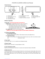
Product Configurations
The PDW-F330/F350 Professional Disc Camcorder series
includes the models PDW-F330L, PDW-F330K, and
PDW-F350L, with different product configurations. The
components and accessories supplied of these models are
as shown in the following figure.
a) Use a tripod adaptor with a suffix of “-E” or later on the model name.
For more details, see “Mounting on a Tripod” (page 47).
1
2
ZOOM
PUSH SET
SHOTMARK
THUMBNAIL
PLAY/PAUSE
STOP
W
.
m
z
>
M
X
xu
PDW-F350L
PDW-F330L
PDW-F330K
T
SUB CLIP
PUSH AFREC PAUSE
REC
FFWDFREV
PREV NEXT
DXF-801/801CE Viewfinder
PDW-F330 Camcorder
Shoulder strap
PDW-F350 Camcorder
Test chart for flange focal
length adjustment
Stereo Microphone VCT-U14 Tripod Adaptor
a)
DXF-20W Viewfinder
VCL-719BXS
Auto Focus Lens
RM-F300 Infrared
Remote Commander
• Lens mount cap
• PFD23 Professional Disc
• PDZ-1 Proxy Browsing Software
• Operating Instructions
(Japanese version, English
version, and CD-ROM manual)
• Warranty Booklet

11
Features
Chapter 1 Overview
Features
The PDW-F330/F350 is an XDCAM
1)
HD
2)
camcorder
integrating an HD video camera using three HD CCDs of
the
1
/2-inch type with a total effective pixel count of 1.56
million, and a Professional Disc
1)
drive.
This unit provides a range of useful shooting functions for
video production, and allows shooting and recording in
both progressive scan and interlace scan modes with an
HD image having 1080 effective scan lines. Since it also
supports SD
3)
DVCAM recording, it can be used through
a transition from SD to HD production.
The use of Professional Disc adds high reliability to
recording and playback, and the unit also includes many
playback and editing functions exploiting the possibilities
of random access.
1) XDCAM and “Professional Disc” are trademarks of Sony Corporation.
2) HD: High Definition
3) SD: Standard Definition
Principal Differences Between the
PDW-F330 and PDW-F350
The specifications of the PDW-F330 and PDW-F350
differ in part, as follows.
a) A DXF-20W 2-inch CRT viewfinder (option) with aspect ratio 16:9 can
be installed in the camcorder.
Camera Features
1
/2-inch HD CCD
The use of three interline transfer CCD
with an effective
pixel count of approximately 1.56 million (1440 ×1080)
enables high sensitivity, high picture quality, and high
fineness video shooting.
Camera signal processing for high quality
video
A specially-developed ASIC (application specific
integrated circuit) for signal processing provides the
following functions.
• A 12-bit A/D converter ensures recording of pictures
stable at high quality.
• Both progressive and interlace scan modes are
supported.
• You can select from five HD shooting/recording modes:
23.98P
1)
, 25P, 29.97P
2)
, 50i, and 59.94i
3)
, for ideal
support of various applications including digital cinema
production, program production, and event video
production.
• For recording and playback in the DVCAM format (SD),
the aspect ratio (16:9/4:3) and standard broadcasting
system (NTSC/PAL) can be freely selected. Further,
when NTSC is selected, video shot at 23.98P can also be
subjected to 2-3 pulldown and recorded. (The recording
format is then 59.94i.)
1) In this system, shown as 23.9P or 23.98P.
2) In this system, shown as 30P.
3) In this system, shown as 60I.
Shooting functions provide various effects
This unit is equipped with many of the functions provided
in a film camera, allowing the operator creative control
through a variety of techniques.
Slow shutter function
A maximum of 64 frames can be accumulated using the
slow shutter function. In low light levels this allows clear
and noiseless video to be shot, and provides a fantasy
video effect with ghost images.
Time lapse function (interval recording)
1)
Using this function slow-moving subjects can be shot with
the movement compressed in time. This is convenient for
many applications, such as monitoring plant growth, or the
progress of a construction site.
1) This function is available when the recording mode is MPEG HD.
Slow & quick-motion functions
1)
The PDW-F350 has slow & quick-motion functions.
These allow the shooting frame rate to be different from
the playback frame rate, allowing the same functions as
overcranking or undercranking with a film camera. Unlike
low-speed or high-speed playback of normally shot video,
this provides a smooth slow-motion effect, or action
speeded up beyond what is actually possible.
1) This function is available when the recording mode is MPEG HD.
Item PDW-F330 PDW-F350
Viewfinder 1.5-inch CRT,
4:3 aspect ratio
(supplied as
standard)
a)
2-inch CRT, aspect
ratio 16:9
(supplied as
standard)
Video output
connectors
BNC ×3 (analog
component
outputs, HD/SD
switchable)
BNC (HDSDI
output)
Audio output
connectors
RCA ×2 XLR, 5-pin
(balanced output)
Timecode input/
output connectors
BNC (input/output
switchable)
BNC ×2
(one for input, the
other for output)
Slow & quick-
motion functions
No Ye s
F350

12
Features
Chapter 1 Overview
Shooting functions to cope with different
shooting conditions
•The ATW
1)
and auto iris functions allow shooting with
automated adjustment of the white balance and intenstity
levels to cope with varying ambient lighting conditions.
• By switching among the four levels (including CLEAR)
of neutral density (ND) filter, it is possible to
compensate for lighting conditions, and control the
depth of field.
• When shooting in daylight or other high color
temperature illumination, pressing the 5600K button
instantly switches the color temperature setting to
5600K
2)
.
• With the GAIN switch, you can adjust the gain of the
video amplifier according to the lighting conditions
when shooting. You can vary the setting in the GAIN
switch positions (H/M/L) to any values in the range –3
dB to +48 dB.
1) Auto Tracing White balance
2) Only when the WHITE BAL switch is in the PRST position
Saving and recalling settings on a
“Memory Stick”
Using a “Memory Stick”
1)
(supplied separately), you can
save menu settings adjusted to particular shooting
conditions, and then recall those settings as required.
1) “Memory Stick” is a trademark of Sony Corporation.
Features of the Optical Disc Drive
(VDR)
Support for HD/SD recording and playback
formats
For HD video recording format, MPEG-2 MP@HL
compression is used, and the image quality (bit rate) and
recording time
1)
can be selected according to the shooting
application. Recording in the DVCAM format is also
supported. The audio is recorded as four channels or two
channels
2)
, uncompressed.
1) The recording mode can be selected from the three modes: HQ (High
Quality), SP (Standard Play) and LP (Long Play).
2) DVCAM recording is available for four channels only.
Proxy AV data recording
The Proxy AV data is low resolution data using MPEG-4
(video 1.5 Mbps, audio 64 kbps per channel). With this
unit, when recording HD or SD high resolution data, low
resolution Proxy AV data is automatically generated at the
same time, and recorded.
Since the Proxy AV data is compact, it can be transferred
to a computer or network at high speed, enormously
reducing the storage capacity required for recording.
Exploiting this allows a laptop computer to be used for
editing
1)
, allows content management on an inexpensive
and compact server, and makes many other applications
easy to implement.
1) Using the supplied PDZ-1 Proxy Browsing Software, a simple EDL (edit
decision list) can be created.
Saving general-purpose files
The Professional Disc has an area of approximately 500
MB provided for storing general-purpose computer files.
Recording and playback in clip units
A clip is created each time recording is started and
stopped.
• Recording always writes to an empty area of the disc.
Therefore, even if playback is carried out between
shooting sessions, there is no danger of the next shooting
inadvertently overwriting previous material. During
playback, the next they are recorded can always be
started immediately.
• Since unwanted clips can be deleted on this unit
immediately after they are recorded, the disc capacity
can be used effectively.
Convenient playback and search functions
exploiting the disc characteristics
Thumbnail search
Pressing the THUMBNAIL button on this unit displays a
representative image for each clip as a thumbnail on the
LCD (liquid crystal display) monitor, in the viewfinder,
and on the external video monitor.
Selecting a thumbnail with the cursor and pressing the
PLAY/PAUSE button allows any clip to be checked
easily.
Essence mark search
During or after movie recording, an essence mark can be
recorded on any scene. A list of frames with an essence
mark recorded can be displayed on the LCD monitor, in
the viewfinder, and on the external video monitor. Essence
marks can also be added after recording using the supplied
PDZ-1 Proxy Browsing Software.
Expand function
The length of any clip selected in the thumbnail list can be
divided into 12, and the first frames of these 12 divisions
can also displayed in the form of a thumbnail list. With this
function, it is easy to search rapidly for scenes within a
particular clip. This function is called the expand function,
and it can be applied to the same clip up to three times to
display 1728 thumbnails in a list.

13
Features
Chapter 1 Overview
Scene selection
You can select clips on the disc to create a clip list. The
clips in this list can be played back in any order. A single
disc can hold up to 99 clip lists.
Audio recording functions
Audio is recorded as uncompressed data with 16-bit
quantization, and a sampling frequency of 48 kHz.
Depending on shooting requirements and recording time,
either two or four audio channels can be selected. (Only
four channels for DVCAM recording.)
• The unit is equipped with a stereo front microphone.
• There are two AUDIO IN connectors (XLR, 3-pin) on
the rear of the unit, which can be used for line and
microphone input.
• The CA-WR855 Camera Adaptor (supplied separately)
can be used to install the WRR-855 series slot-in type
UHF synthesized tuner (supplied separately) without
using any connecting cable.
• The audio signals to be recorded on the disc can be freely
selected from the audio inputs to the stereo microphone,
AUDIO IN connectors and the UHF synthesized tuner,
and assigned to any desired audio channel.
Input/Output Features
Equipped with an i.LINK connector
The i.LINK connector on this unit supports the following
two functions.
DV stream output (AV/C
1)
mode connection): A DV
stream can be output from the i.LINK connector on
this unit, and recorded on a DV recorder or nonlinear
editor supporting DV. For recording and playback in
MPEG HD format, a down-converted DV stream can
be output.
File access from a computer (FAM
2)
connection): An
FAM connection between this unit and a computer
allows the video, audio, and metadata information on
the disc to be read and written as files. (The data can
be written and read as normal files on a computer.)
With this function, a nonlinear editing device
connected to this unit can be used for direct HD video
editing or simple Proxy A/V data editing, enabling a
more efficient workflow.
1) Audio/Video Control
2) File Access Mode
Other signal input/output connectors
HDSDI output connector
The audio signals are embedded in the video signal. The
HD video and audio output from this connector can be
recorded on an external HD device.
HD/SD analog component output connector
During HD video recording and playback, either an HD
signal or down-converted SD signal can be output. (The
output signal selection is carried out in a menu.)
Composite video output connector
The 50i/25P video is output as the PAL signal, the 60i/30P
video is output as the NTSC signal, and the 23.98P video
is output as the NTSC signal which has undergone 2-3
pull-down processing.
Timecode input/output connectors
Provided with a single input/output connector (controlled
by a switch).
Provided with one input connector and one output
connector.
GENLOCK connector
The SD or HD reference signal can be input to apply a
genlock to the camera.
Video light connector
There is an interface connector for a maximum 50 W video
light, and a control switch. Depending on the switch
setting, the light can be turned on and off as recording
starts and stops.
Remote control connector
Connect the RM-B150/B750 remote control unit (supplied
separately) or other remote commander, to allow remote
operation of the shooting functions of this unit.
Audio output connectors
Provided with RCA phono jacks, allowing stereo output.
Provided with XLR connectors (5-pin, balanced output),
allowing stereo output.
Earphone jack (monaural/stereo)
Audio channels to be monitored can be selected with the
MONITOR switch on the side of the unit. Switch between
monaural and stereo using the menus.
F350
F330
F330
F350
F330
F350

14
Features
Chapter 1 Overview
Other Features
User-friendly interface functions
ASSIGN (assignable) switches
The unit is provided with four ASSIGN switches; two on
the front and the others on the top of the grip. You can
assign various functions to these switches. By assigning
frequently used functions to the switches, you can call up
the desired functions instantly, for example during
shooting operations. The functions that can be assigned are
as follows.
• Lens zoom control (telephoto/wide-angle)
• Easy focus function
• Turbo gain function
• Enabling and disabling the infrared remote commander
function
Infrared remote commander
You can use the supplied infrared remote commander to
carry out the following operations.
• Starting and stopping recording, auto focusing, zoom
control (telephoto/wide-angle)
• Recording essence marks (shot mark 1 and shot mark 2)
• Playback, high-speed playback / reverse high-speed
playback, jump to the next/previous clip
• Thumbnail display and selection, a clip list selection
To prevent misoperation, the remote commander function
is disabled when this unit is powered on. To use the
infrared remote commander, you must enable the remote
commander function using a menu. If you use the remote
commander frequently, it is recommended that you assign
the function of this menu to one of the ASSIGN switch.
3.5-inch color LCD monitor
The LCD monitor on the side of the unit can be switched
to show the following images and data.
• Status information, including audio level meters for four
channels and timecode
• List of thumbnails of the video recorded on the
Professional Disc
• A playback image of the video recorded on the
Professional Disc
•The camera image
• The image in the LCD monitor has about 4% cropped
from each of the four edges of the actually captured
video image. For accurate framing, always use the
viewfinder.
• When the area of use is set to “PAL AREA” (frame
frequency 50i or 25P), the image in the LCD monitor
may be reduced in quality, with jaggies on diagonal
lines, but this is not a malfunction.
Note
Notes

15
Location and Function of Parts
Chapter 1 Overview
Location and Function of Parts
Front
a Lens mount securing rubber
After locking the lens in position using the lens locking
lever, fit this rubber over the lower of the two projections.
This fixes the lens mount, preventing it from coming loose.
b Lens mount cap
Remove by pushing up the lens locking lever (see page
16). When no lens is mounted, keep this cap fitted for
protection from dust.
c LENS connector (12-pin)
Connect the lens cable mainly for using a
2
/3-inch type
lens. (This connector is not used for a
1
/2-inch type lens,
which is connected by the hot shoe inside the lens mount.)
Consult your Sony dealer when you are using a lens other
than VCL-719BXS (supplied with the PDW-F330K).
When mounting or removing the lens on this unit, power
off this unit first.
d AUTO W/B BAL (automatic white/black balance
adjustment) switch
Activates the automatic white/black balance adjustment
functions.
WHT: Adjusts the white balance automatically. If the
WHITE BAL switch
(see page 18) is set to A or B, the
white balance setting is stored in the corresponding
memory. If the WHITE BAL switch is set to PRST,
the automatic white balance adjustment function does
not operate.
BLK: Adjusts the black set and black balance
automatically.
e REC (recording start) button
Press to start recording. Press it again to stop recording.
The effect is the same as that of the REC button on the
supplied lens. When the REC SWITCH function is
assigned to an ASSIGN switch on the ASSIGNABLE page
of the OPERATION menu, you can use the switch as the
REC button.
f Auto focus ranging sensor
When an VCL-719BXS (supplied with the PDW-F330K)
auto focus lens is mounted, this measures the distance to
the subject, and automatically focuses the lens.
This sensor is provided as an auxiliary function for
improving the automatic focusing speed. Even if this
sensor is blocked, the focusing precision will not be
affected.
g VF (viewfinder) connector (20-pin)
Connect the supplied viewfinder.
h Lens mount (special bayonet mount)
Attach the lens.
i FILTER selector
Selects from the four neutral density (ND) filters built into
this unit.
5 REC button
2 Lens mount cap
4 AUTO W/B BAL switch
8 Lens mount
9 FILTER selector
3 LENS connector
7 VF connector
0 ZEBRA button
qa ASSIGN 1/2 switches
qs Lens locking lever
qd MENU knob
qf SHUTTER switch
qh AUDIO LEVEL knob
1 Lens mount securing rubber
6 Auto focus ranging
sensor
qg Remote commander receptor
Note
Position
number
ND filter
1 CLEAR
2
1
/4 ND (attenuates light to approximately
1
/4)
3
1
/16 ND (attenuates light to approximately
1
/16)
4
1/
64 ND (attenuates light to approximately
1
/64)

16
Location and Function of Parts
Chapter 1 Overview
Normally set this to 1 (CLEAR).
For shooting with the lens iris wide open for reduced depth
of field, or when the subject is too brightly lit and the auto
iris function does not operate correctly, select an
appropriate position.
When this selector is used with the menu item for filter
selection display set to ON
(see page 139), the new setting
appears on the viewfinder screen for about 3 seconds.
You can change a MAINTENANCE menu setting so that
different white balance settings can be stored for different
FILTER selector positions. This allows you to
automatically obtain optimum white balance for the
current shooting conditions in linkage with the filter
selection.
For details, see “To adjust the white balance” (page 62).
j ZEBRA button
Press to display a zebra pattern (diagonal stripes) in the
viewfinder screen.
The zebra pattern is factory set to indicate picture areas
where the video level is approximately 70%. However, on
the VF SETTING page of the OPERATION menu, you
can change the setting so that areas where the video level
is 100% and above are also indicated at the same time. In
addition, you can also change the video level for
displaying the zebra pattern in the range from 30% to
107%.
For details, see “Setting the Viewfinder Screen Display”
on page 140.
k ASSIGN 1/2 switches
You can assign the desired functions to each of the
ASSIGN 1 and ASSIGN 2 switches on the ASSIGNABLE
page of the OPERATION menu.
The following functions are factory preset to the switches.
For details, see “Assigning Functions to ASSIGN
Switches” on page 145.
l Lens locking lever
After inserting the lens in the lens mount, rotate the lens
mount ring with this lever to lock the lens in position.
After locking the lens, be sure to use the lens mount
securing rubber to prevent the lens from becoming
detached.
m MENU knob
Changes the page selection or a setting within the menu.
For details about how to use the MENU knob, see “Basic
Menu Operations” on page 133.
n SHUTTER switch
Set to ON to use the electronic shutter. Flick to SEL to
switch the shutter speed or shutter mode setting within the
range previously set with the menu. When this switch is
operated, the new setting appears on the setting change/
adjustment progress message display area for about 3
seconds.
For details about the shutter speed and shutter mode
settings, see
“Setting the Electronic Shutter” on page 64.
o Remote commander receptor
Press the ASSIGN switch which is assigned to enable/
disable the remote commander function, and then aim the
supplied infrared remote commander at this receptor.
To prevent misoperation, the remote commander function
is disabled when the camcorder is powered on. To use the
infrared remote commander, it is necessary to assign the
remote commander enabling/disabling function to an
ASSIGN switch, and then press the ASSIGN switch to
enable the remote commander. (This function is factory
preset to the ASSIGN 2 switch.)
For details of how to assign a particular function to an
ASSIGN switch, see
page 145.
p AUDIO LEVEL knob
Adjusts the input level of audio channels 1and 2.
You can disable this knob by setting the AUDIO CH1
LEVEL and AUDIO CH2 LEVEL items on the AUDIO-1
page of the MAINTENANCE menu. (The knob is factory
preset so that it is enabled.)
Switch Function
ASSIGN 1 EZ MODE (EZ mode ON/OFF)
ASSIGN 2 IR REMOTE (infrared remote commander
enabled/disabled)
Note

17
Location and Function of Parts
Chapter 1 Overview
Right Side
Near the front
a 5600K button
Press to light the button and switch the standard color
temperature for shooting to 5600K. Use this button for
outdoor shooting in daytime or shooting under lighting
with higher temperature. This button is effective only
when the WHITE BAL switch is set to PRST.
b LIGHT switch
Determines how a video light connected to the LIGHT
connector
(see page 25) is turned on and off.
AUTO: When the POWER switch of the video light is in
the on position, the video light is turned on
automatically while the camcorder is recording.
MAN: You can turn the video light on or off manually,
using its own switch.
• When this switch is set to AUTO, at the beginning of the
recording, the picture is recorded even though the
lighting may fluctuate until the video light comes on. If
the beginning of the recording is important, you should
set this switch to MAN. However, when using the
interval recording mode, the video light is automatically
turned on immediately before recording starts.
• To ensure proper operation of the video light, Sony
recommends the use of the BP-GL95 Battery Pack with
the camcorder.
c GAIN switch
Switches the gain of the video amplifier to match the
lighting conditions during shooting. The gains
corresponding to the L, M, and H settings can be selected
in the menu. (The factory settings are L = 0 dB, M = 9 dB,
and H = 18 dB.)
When this switch is adjusted, the new setting appears on
the setting change/adjustment progress message display
area of the viewfinder screen for about 3 seconds.
For details, see “Setting Gain Values for the GAIN Switch
Positions” on page 143.
d VDR SAVE/STBY (VDR save/standby) switch
Switches the status of the power supply to the VDR while
recording is paused (REC PAUSE).
SAVE: At the start of recording, an internal operating
sound may be recorded. There is a small delay from
pressing the REC button until recording starts, since
the power consumption is less than in the standby
state.
STBY: When the REC button is pressed, recording starts
immediately.
• Even if the switch is on the SAVE side, the unit exits
SAVE (power saving) mode and enters STBY (standby)
mode whenever you exit REC PAUSE mode by carrying
out playback to check the recorded video or by
displaying the thumbnail screen
(page 84). To put the
unit into SAVE mode again, put the unit into REC
PAUSE mode again after recording, or power the unit
off and on again.
• An internal operating sound may be recorded at the start
of recording when the VDR SAVE/STBY switch is set
to SAVE.
e POWER switch
Turns the main power supply on and off.
f MONITOR (monitor volume adjustment) knob
Controls the volume of the sound other than the warning
tone that is output via the built-in speaker or optional
earphones. When the knob is turned to the minimum
setting, no sound can be heard.
qa OUTPUT/DCC switch
1 5600K button
3 GAIN switch
6 MONITOR knob
7 ALARM knob
2 LIGHT switch
5 POWER switch
8 LCD monitor
9 MENU switch
0 WHITE BAL switch
4 VDR SAVE/STBY switch
Notes
Notes

18
Location and Function of Parts
Chapter 1 Overview
g ALARM (alarm tone volume adjustment) knob
Controls the volume of the warning tone that is output via
the built-in speaker or optional earphones. When the knob
is turned to the minimum position, no sound can be heard.
h LCD monitor
Displays camera video, VDR-related warnings, remaining
battery capacity, remaining disc space, audio levels, time
data, and so on.
For details, see “Status Display on the LCD Monitor” on
page 19.
i MENU switch
When flicking toward ON, the menu is displayed. When
flicking toward STATUS, the status of the camcorder (of
current settings) is displayed.
For details, see “Displaying Menus” on page 133.
j WHITE BAL (white balance memory) switch
Controls adjustment of the white balance.
PRST: Adjusts the color temperature to the preset value
(the factory default setting: 3200K). Use this setting
when you have no time to adjust the white balance.
A or B: Recall the white balance adjustment settings
already stored in A or B.
Press the AUTO W/B BAL switch (see page 15) on
the WHT side, to automatically adjust the white
balance, and save the adjustment settings in memory
A or memory B. The 5600K button does not function.
You can use the AUTO W/B BAL switch even when
ATW
1)
is in use.
B (ATW): When this switch is set to B and WHITE
SWITCH <B> is set to ATW on the WHITE
SETTING page of the MAINTENANCE menu, ATW
is activated. When this switch is adjusted, the new
setting appears on the setting change/adjustment
progress message display area of the viewfinder
screen for about 3 seconds. You can assign the ATW
function to an ASSIGN switch on the ASSIGNABLE
page of the OPERATION menu.
For details about how to assign the function to an ASSIGN
switch, see
“Assigning Functions to ASSIGN Switches” on
page 145.
1) ATW (Auto Tracing White Balance): The white balance of the picture
being shot is adjusted automatically for varying lighting conditions.
k OUTPUT/DCC (output signal/dynamic contrast
control) switch
Switches the video signal, which is output to the video disc
drive (referred to as “VDR”), viewfinder, and video
monitor from the camera section, between the following
two.
BARS: Outputs the color bar signal.
CAM: Outputs the video signal from the camera. When
this is selected, you can switch DCC
1)
on and off.
1) DCC (Dynamic Contrast Control): Against a very bright background
with the iris opening adjusted to the subject, objects in the background will
be lost in the glare. The DCC function will suppress the high intensity and
restore much of the lost detail and is particularly effective in the following
cases.
• Shooting people in the shade on a sunny day
• Shooting a subject indoors, against a background through a window
• Any high contrast scene
LCD monitor operating buttons
a DISPLAY/EXPAND button
Each time pressing this button, the display in the LCD
monitor changes as follows.
ALARM
Minimum Maximum
OUTPUT
DCC
CAMBARS
ONOFF
OUTPUT: BARS, DCC: OFF
A color bar signal is output and the DCC circuit does not
operate. Use this setting to adjust the video monitor, to
record the color bar signal, etc.
OUTPUT: CAM, DCC: OFF
The video signal from the camera is output, and
the DCC circuit does not operate.
OUTPUT: CAM, DCC: ON
The video signal from the camera is output, and
the DCC circuit operates.
1 DISPLAY/EXPAND button
2 COUNTER/CHAPTER button
3 RESET button
4 BRIGHT button

19
Location and Function of Parts
Chapter 1 Overview
If you press this button when the thumbnail screen is
displayed, the duration of the selected clip is divided into
12, and the first frame of each of the divisions is shown in
a further thumbnail display (expand function). Each time
you press the button, the division is repeated (to a
maximum of three times, with 1728 divisions). Hold down
the SHIFT button and press this button to step back
through the division process.
For details of the expand function, see page 87.
b COUNTER/CHAPTER (counter display toggle/
chapter) button
Each time this button is pressed, the counter display
section changes as follows. This setting is activated only
when the LCD monitor display is set to STATUS with the
DISPLAY/EXPAND button.
COUNTER: Displays the elapsed recording/playback
time.
TC: Displays timecode.
U-BIT: Displays user bits data.
If you press this button when the thumbnail screen is
displayed, those frames on which essence marks are
recorded appear in a list (chapter function). Press the
button once more to return to the normal thumbnail
display.
By displaying thumbnails with essence marks attached in
place of index frames, you can check the contents of clips
more easily and more quickly. This is also useful for
cueing up long clips.
For details of the chapter function, see page 87.
c RESET button
Resets the display of the time data when the LCD monitor
display is set to STATUS or CHAR with the DISPLAY/
EXPAND button. According to the settings of the
PRESET/REGEN/CLOCK switch
(see page 24) and the
F-RUN/SET/R-RUN switch (see page 24), this button
resets the display as follows.
a) Of the timecode bits for every frame recorded on the disc, those bits which
can be used to record useful information for the user such as scene number,
shooting place, etc.
b) Can only be reset when the display is set to STATUS. When it is set to
CHAR, resetting is not possible.
For details, see “Setting the Time Data” on page 68.
If you press this button when thumbnails of frames with
essence marks are displayed using the COUNTER/
CHAPTER button, or when thumbnails of clip divisions
are displayed using the DISPLAY/EXPAND button, then
the display returns to the normal thumbnail display.
d BRIGHT (brightness) button
Sets the backlight brightness. Each time you press this
button, the backlight brightness cycles through the
following four levels:
H: Select this to view the LCD monitor in outdoor
daylight.
M: Brightness level between H and L.
L: Select this to view the LCD monitor indoors or outside
at night.
OFF: Turn the backlight off (you can view video under
normal lighting). Select this in outdoor daylight when
the LCD monitor screen is subjected to direct
sunlight.
Status Display on the LCD Monitor
The following display appears when the LCD monitor
display is set to STATUS with the DISPLAY/EXPAND
button.
Display indication Meaning
Video with
superimposed
information
When the MENU switch is flicked
toward STATUS, the principal settings
of this unit appear as on the
viewfinder screen.
Video without
superimposed
information
The video only appears.
Status display Counter indications, warnings, audio
levels, and similar information
appears. No video image appears.
Settings of buttons and
switches
To reset
COUNTER/CHAPTER button:
COUNTER
Counter to 0:00:00:00
COUNTER/CHAPTER button:
TC
PRESET/REGEN/CLOCK
switch: PRESET
F-RUN/SET/R-RUN switch: SET
Timecode to 00:00:00:00
COUNTER/CHAPTER button:
U-BIT
PRESET/REGEN/CLOCK
switch: PRESET
F-RUN/SET/R-RUN switch: SET
User bits data
a)
to 00 00
00 00
b)
Settings of buttons and
switches
To reset
WARNING:HUMID
HD SP
TCG
01: 23: 45 15:
23.98P 4ch
H
PB NDF EXT-LK
21
HOLD
MIN SEC FRM
DISC E B
BATT E F Li
ST
43
dB
OVER
PEUK
2
0

20
Location and Function of Parts
Chapter 1 Overview
a Video format
Indicates the format of video being currently played back
or recorded.
HD HQ: HQ (high quality) mode in the MPEG HD video
format
HD SP: SP (standard play) mode in the MPEG HD video
format
HD LP: LP (long play) mode in the MPEG HD video
format
DVCAM: DVCAM format
b Playback indicator
Appears during playback.
c Camera scan mode indicator
Indicates the camera scan mode of video being currently
played back or recorded.
• If NTSC AREA is selected
1)
60I: 59.94 fields per second, interlace scan mode
30P: 29.97 frames per second, progressive scan mode
23.98P: 23.98 frames per second, progressive scan mode
(converted to 60i at 2-3 pulldown)
• If PAL AREA is selected
1)
50I: 50 fields per second, interlace scan mode
25P: 25 frames per second, progressive scan mode
1) COUNTRY setting on the FORMAT page of the OPERATION menu (see
page 113).
There may be no indication displayed when this unit
cannot identify the camera scan mode, for example, when
playing back a disc recorded with other equipment.
d Non-drop-frame mode indicator
Appears when non-drop-frame timecode is selected.
e External synchronization indicator
Appears when the internal timecode generator is locked to
an external signal input to the TC IN connector
1)
.
1) For the PDW-F350. For the PDW-F330, the TC connector (IN/OUT
switch set to IN).
f Audio channel display
Shows the audio channel mode during recording or
playback.
2ch: two-channel mode (only when the MPEG HD format
is selected)
4ch: four-channel mode
g Hold indicator
Appears when the internal timecode generator is stopped.
h Audio level indicators
Indicates the audio recording or playback levels of
channels 1 to 4.
i Lithium battery low voltage warning
Appears when the voltage of the internal lithium backup
battery (CR2032) is low. If this indication appears, replace
the lithium battery immediately
(see page 38).
j Remaining battery capacity indicator
k Remaining disc capacity indicator
l Warning indicator area
Displays warnings when trouble with recording or
moisture condensation occurs.
For details, see “Operation Warnings” on page 168.
Note
Indication Battery voltage
BP-L90A/L60S/
L80S
Other
batteries
BATT E [ ■■■■■■■ ] F 15.5 V or more 17.0 V or more
BATT E [ ■■■■■■ ] F 15.1 to 15.5 V 16.0 to 17.0 V
BATT E [ ■■■■■ ] F 14.6 to 15.1 V 15.0 to 16.0 V
BATT E [ ■■■■ ] F 13.8 to 14.6 V 14.0 to 15.0 V
BATT E [ ■■■ ] F 12.9 to 13.8 V 13.0 to 14.0 V
BATT E [ ■■ ] F 12.0 to 12.9 V 12.0 to 13.0 V
BATT E [ ■ ] F 10.8 to 12.0 V 11.0 to 12.0 V
BATT E [ ] F 10.8 V or less 11.0 V or less
Indication Battery voltage
BP-GL95/GL65/IL75/
M100, Anton Bauer
Battery System
BATT E [ ■■■■■■■ ] F 80 to 100%
BATT E [ ■■■■■■■ ] 70%
BATT E [ ■■■■■■ ] 60%
BATT E [ ■■■■■ ] 50%
BATT E [ ■■■■ ] 40%
BATT E [ ■■■ ] 30%
BATT E [ ■■ ] 20%
BATT E [ ■ ] 10%
BATT E [ ] 0%
Indication Remaining recording
time
DISC E [ ■■■■■■■ ] B 30 minutes
DISC E [ ■■■■■■ ] B 25 to 30 minutes
DISC E [ ■■■■■ ] B 20 to 25 minutes
DISC E [ ■■■■ ] B 15 to 20 minutes
DISC E [ ■■■ ] B 10 to 15 minutes
DISC E [ ■■ ] B 5 to 10 minutes
DISC E [ ■ ] B 2 to 5 minutes
DISC E [ ■ ] B (flashing) 0 to 2 minutes
DISC E [ ] B (flashing) 0 minutes
/