Other settings
16
4
zone is also directly and more conveniently settable by access-
ing the main heating settings page, as described in Paragraph
2.4
p.8
or 3.4
p.14
.
To change these settings, go to the conguration settings page
as described in Paragraph 4
p.14
, then proceed as follows:
1. Turn the knob to preselect the Setting eld, then press the
knob to select it; this causes the access to the rst settings
page of the rst zone congured on the device, identied by
the Heating zone i (1/2), where i is 1, 2 or 3 and corresponds
to the rst zone congured on the device.
2. if you need to change the settings for a dierent zone, press
the knob, then turn it until the rst page of the desired zone
is displayed; if, i.e., you want to change the settings for zone
3, then press and turn the knob unit the page identied by
the Heating zone 3 (1/2) header is displayed, then press the
knob to access that page.
3. Turn the knob to preselect the desired eld, i.e. Comfort
setpoint, Reduced setpoint, or Protection setpoint, then
press the knob to select it; the current value of the eld is
shown in negative; Figure 4.2
p. 16
shows as an example
the page relating to heating zone 3 with Reduced setpoint
eld selected.
4. Turn the knob to set the value and then press it to conrm.
5. Turn the knob to preselect another eld you want to change,
or the Back eld, if no other changes are required on this
page.
6. Press the knob to change the new eld, or to return back to
the conguration settings page (Figure 4.1
p.15
).
7. If no other settings are to be made, turn the knob to prese-
lect the eld and press the knob to return back to the
navigation bar.
Figure4.2 First page of a heating zone settings (in the example zone 3)
with the Reduced setpoint eld selected
4.4.2 Second page: heating curve slope, summer/
winter heating limit
Access to this page and the change of the parameters contained
therein by the end user is required only to change some particu-
lar settings; in case of doubt, contact the TAC.
To change these settings, go to the conguration settings page
as described in Paragraph 4
p.14
, then proceed as follows:
1. Turn the knob to preselect the Setting eld, then press the
knob to select it; this causes the access to the rst settings
page of the rst zone congured on the device, identied by
the Heating zone i (1/2), where i is 1, 2 or 3 and corresponds
to the rst zone congured on the device.
2. Press the knob, then turn it until the second page of the de-
sired zone is displayed; if, i.e., you want to change the set-
tings for zone 2, then press and turn the knob unit the page
identied by the Heating zone 2 (2/2) header is displayed,
then press the knob to access that page.
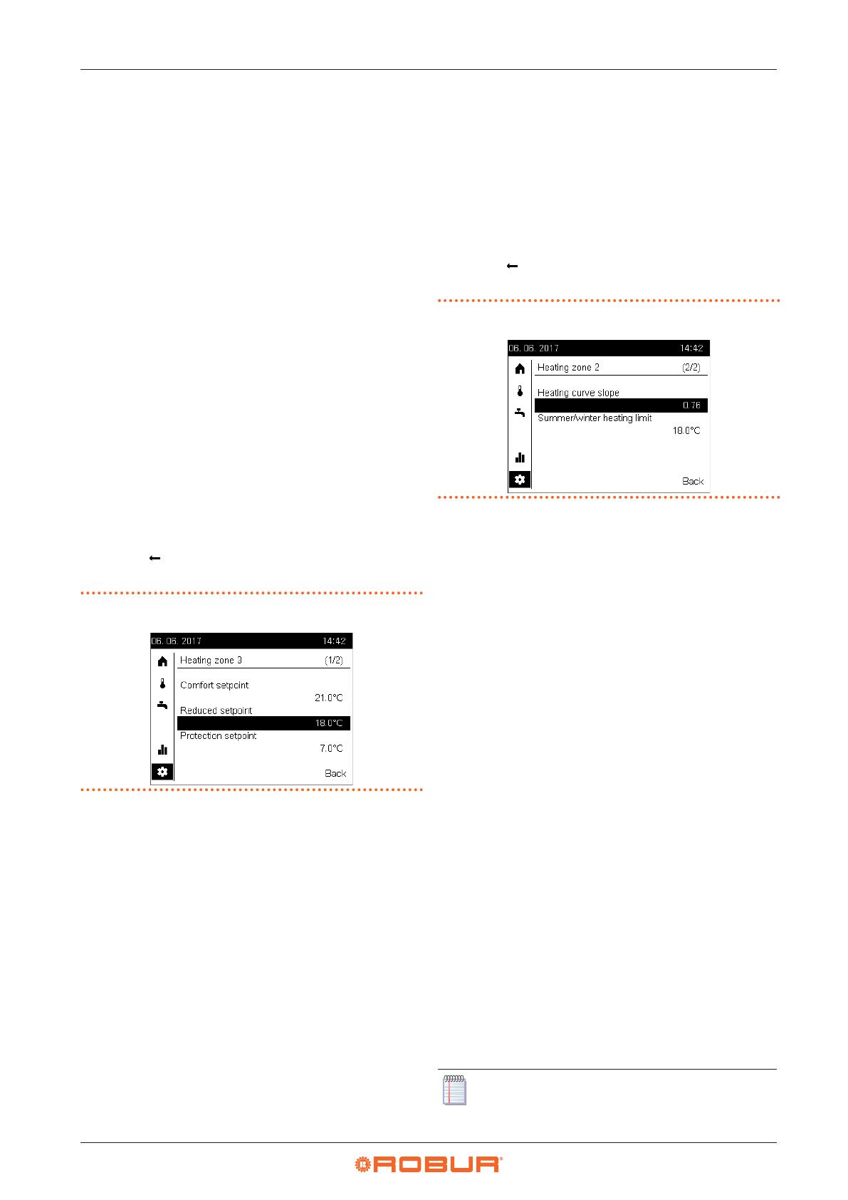
3. Turn the knob to preselect the desired eld, i.e. Heating
curve slope or Summer/winter heating limit, then press
the knob to select it; the current value of the eld is shown in
negative; Figure 4.3
p. 16
shows as an example the page
relating to heating zone 2 with Heating curve slope eld
selected.
4. Turn the knob to set the value and then press it to conrm.
5. Turn the knob to preselect another eld you want to change,
or the Back eld, if no other changes are required on this
page.
6. Press the knob to change the new eld, or to return back to
the conguration settings page (Figure 4.1
p.15
).
7. If no other settings are to be made, turn the knob to prese-
lect the eld and press the knob to return back to the
navigation bar.
Figure4.3 Second page of a heating zone settings (in the example zone
2) with the Heating curve slope eld selected
Below is a description of the two parameters that can be set on
this page.
Heating curve slope
Each heating circuit (or zone) has its own heating curve. The
heating curve enables the system to modify the outlet temper-
ature as a function of outdoor temperature, adapting the heat
output delivered to the terminals (radiators, fan coil units, oor
radiators, etc.) to the building's actual heating requirements.
It follows that the outlet temperature will be higher for lower
external temperatures, while it will be lower for higher external
temperatures.
This technique has considerable advantages compared to con-
stant outlet temperature solutions:
▶
Room comfort is greatly improved thanks to a delivery of
thermal power which is commensurate to need, and hence
more constant; this avoids alternating periods of excessive
heating with periods of no heating at all, which results in os-
cillating room temperature.
▶
The system is more ecient thanks to the higher eciency
of the K18 heat pump and lower thermal dispersion, both
due to the lower water temperature delivered during the
greater part of the cold season; the result is considerable
cost savings.
Depending on the type of terminal and their size, one must set
the correct heating curve as a function of the slope parameter.
When rst starting up the system, the installer set this parameter
to a value suited to the type and size of terminals for each zone.
However, after a a rst period of operation in variable climate
conditions, you may remark that the room temperature is not
constant with variations in the external temperature; in particu-
lar, two cases may arise:
1. The room temperature is lower when outdoor temperature
is lower.
2. The room temperature is higher when outdoor temperature
is lower.
In order to avoid wrong conclusions, this assessment
should be based on several observations, each of which
should be carried out as follows:


