Yamato Scientific HC200 Operating instructions
- Type
- Operating instructions

INSTRUCTION MANUAL
FOR
Cool Block
The 1st Edition
The 1st EditionThe 1st Edition
The 1st Edition
Yamato Scientific
Yamato Scientific Yamato Scientific
Yamato Scientific Co
CoCo
Co.
..
., Ltd.
, Ltd., Ltd.
, Ltd.
2-1-6, Nihonbashi Honcho, Chuo-ku
2-1-6, Nihonbashi Honcho, Chuo-ku2-1-6, Nihonbashi Honcho, Chuo-ku
2-1-6, Nihonbashi Honcho, Chuo-ku
Tokyo 103-8432 JAPAN
Tokyo 103-8432 JAPANTokyo 103-8432 JAPAN
Tokyo 103-8432 JAPAN
Congratulations on your selection of Yamato Scientific’s Cool Block HC200!
Please read these operating instructions, user notes and the warranty card thoroughly before the
initial operation of your HC200. This will ensure proper operating procedures and extended life for
the unit. Please keep the operating instructions together with the warranty card for easy access
whenever you need them.

TABLE OF CONTENTS
Explanation of picture display..................................................................................................1
Cautions in using with safety...................................................................................................2
Notes to Users...........................................................................................................................3
DESCRIPTION AND FUNCTION OF EACH PART...................................................................................3
REQUIREMENTS FOR INSTALLATION ...................................................................................................5
SELF-DIAGNOSTIC FUNCTIONS..............................................................................................8
FIXED TEMPERATURE OPERATION........................................................................................9
Start up.......................................................................................................................................................9
Changing Preset Temperature during Operation..................................................................................... 11
Program Operation..................................................................................................................12
Start up.....................................................................................................................................................12
Changing Operation Mode......................................................................................................15
Changing to Quick Auto-Stop Mode.........................................................................................................15
Changing the Program Operation during Fixed Temperature Operation.................................................17
Changing from Program Operation to Fixed Temperature Operation......................................................18
Changing from Program Operation to Other Program Operation............................................................19
Menu Functions.......................................................................................................................20
Changing Sub Display Screens ...............................................................................................................22
Setting and releasing Panel Locking System...........................................................................................23
Setting and releasing the Alarm...............................................................................................................24
Setting and releasing the Temperature Holding Function........................................................................25
The Escape Function ...............................................................................................................................26
The Abort (Forced Stop) Function............................................................................................................27
How to Use Temperature Presetting Function ......................................................................28
Register Preset Temperature...................................................................................................................28
Loading a Preset Temperature.................................................................................................................30
Canceling to Load a Preset Temperature ................................................................................................30
Resume Function....................................................................................................................31
The behavior after turning on the power switch.......................................................................................31
Setting and releasing the resume function...............................................................................................32
How to release from the state after the power restoration.......................................................................33
The display after the power restoration when the resume function is in activity......................................34
How to Compose a Program...................................................................................................35
Program Composition ..............................................................................................................................35
Inputting a Program..................................................................................................................................39
Editing a Program ....................................................................................................................................45
Deleting a Program ..................................................................................................................................47
Maintenance ............................................................................................................................48
Daily Inspection and Maintenance...........................................................................................................48
After service and WARRANTY................................................................................................49
If a Service Call is required:.....................................................................................................................49
TROUBLESHOOTING.............................................................................................................................49
SPECIFICATIONS.....................................................................................................................50
WIRING DIAGRAM...................................................................................................................51
REPLACEMENT PARTS TABLE..............................................................................................52
Optional accessories ..............................................................................................................53
Reference.................................................................................................................................54
Flowchart on the Operating Procedure....................................................................................................54
Explanation of Character on the display..................................................................................................56

1
Explanation of picture display
MEANING OF ILLUSTRATED SYMBOLS
Various symbols are used in this safety manual in order to use the unit without
danger of injury and damage of the unit. A list of problems caused by ignoring the
warnings and improper handling is divided as shown below.Be sure that you
understand the warnings and cautions in this manual before operating the unit.
Warning
If the warning is ignored, there is the danger of a problem that may
cause a serious accident or even fatality.
Caution
If the caution is ignored, there is the danger of a problem that may
cause injury/damage to property or the unit itself.
Meaning of Symbols
This symbol indicates items that urge the warning (including the caution).
A detailed warning message is shown adjacent to the symbol.
This symbol indicates items that are strictly prohibited.
A detailed message is shown adjacent to the symbol with specific actions not to
perform.
This symbol indicates items that should be always performed.
A detailed message with instructions is shown adjacent to the symbol.
Illustrated Symbols

2
Cautions in using with safety
WARNING
Do not use the unit in an area where there is flammable or explosive gas.
•
••
•
Never use the unit in an area where there is flammable or explosive gas.
The unit is not explosion-proof. An arc may be generated when the power switch is turned on or off, and
fire/explosion may result.
Always ground the unit.
•
••
•
Always ground the unit on the power equipment side in order to avoid electrical shock due to a power surge.
If a problem occurs, you should:
•
••
•
If smoke or strange odor should come out of the unit for some reason,
turn off
the power key right away, then
turn
off
the circuit breaker and the main power. Immediately contact a service technician for inspection. If this
procedure is not followed, fire or electrical shock may result.
Never perform repair work yourself, since it is dangerous and not recommended.
Do not use the power cord if it is bundled or tangled.
•
••
•
Do not use the power cord if it is bundled or tangled. If it is used in this manner, it can overheat and fire may be
caused.
Do not process, bend, wring, or stretch the power cord forcibly.
•
••
•
Do not process, bend, wring, or stretch the power cord forcibly. Fire or electrical shock may result.
Substances that can not be used.
•
••
•
Never use explosive substances, flammable substances and substances that include explosive or flammable
ingredients in the unit. Explosion or fire may occur.
Do not disassemble or modify the unit.
•
••
•
Do not reconfigure the unit. Fire or electrical shock may be caused.
CAUTION
During a thunder storm
•
••
•
During a thunder storm,
turn off
the power key immediately, then
turn off
the circuit breaker and the main power.
If this procedure is not followed, fire or electrical shock may be caused.

3
Notes to Users
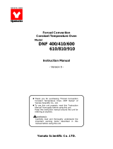
DESCRIPTION AND FUNCTION OF EACH PART
Main unit
Front view
Rear view
Intake
p
ort
Aluminum block (optional)
Aluminum block installing knob
(
e
q
ui
pp
ed with an Aluminum block
)
Cover
Control panel
Power supply switch
with a over current breake
r
Exhaust ports
Cooling fan
Intake
p
ort

4
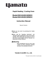
Control Panel
FIXED-TEMP
PROGRAM
HEAT
STAND BY
MEASURED TEMP
MENU
MODE
ENTER
Main Display:
Normally shows the
aluminum block’s
temperature.
Sub Display:
Shows the preset temperature, remaining time and
ongoing program number
Heater (
HEAT
) lamp:
Lights up when electric power is supplied to the heater.
Standby (
STANDBY
) Lamp
Lights up when HC200 is ready for the program
operation.
Function menu (
MODE
) key:
Use this key when you select a desired function.
Up/Down key:
Use these keys when you change the parameters.
Blind Window:
Blank in normal operation. “TROUBLE” lamp lights
up when HC200 has a problem, and “REMOTE” lamp
lights up when the optional communication system is in
use.
Operation Mode Indicator:
Indicates if HC200 is on the fixed temperature operation
or the program operation.
Operation Menu (
MENU
) key:
Use this key when you change operation mode.
ENTER
key:
Use this key when you accept a modified parameter.

5
REQUIREMENTS FOR INSTALLATION
Warning
WarningWarning
Warning
Do not use the unit in an area where there is flammable or explosive gas.
•
Never use the unit in an area where there is flammable or explosive gas. The unit is not explosion-
proof. An arc may be generated when the power switch is turned ON or OFF, and fire/explosion may
result.
Always ground the unit.
•
Connect HC200’s power plug to a receptacle with grounding connectors.
•
Do not forget to ground HC200, to protect you and the unit from electrical shock in case of power surge.
Choose a receptacle with grounding connectors as often as possible.
•
Do not connect the grounding wire to a gas pipe, or by means of a lightning rod or telephone line. A fire
or electrical shock will occur.
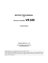
•
If only bipolar receptacles are available for
HC200, connect an optional grounding
adapter to HC200’s power plug. Check
the polarity of the receptacle before
connecting the adapter to the receptacle.
Connect the adapter’s grounding wire
(green) to a grounding terminal to the power
supply. Contact our sales representative
in your vicinity or our service center for
additional information or assistance.
100V receptacle with grounding terminals
Power plug
100V bipolar receptacle
Grounding wire

6
Choose a correct power distribution board or receptacle.
•
Choose a correct power distribution board or receptacle that meets HC200’s rated electric capacity.
Electric capacity : 100 VAC, 3A
•
Do not connect HC200 to an outlet that differs from the above specifications because a fire or electrical
shock will occur.
Install on a level area.
•
Do not installation HC200 on a
non level surface. This will
cause hazards to the operator
and create problems during
actual operation.
Choose a proper place for installation.
•
Do not install HC200 in a place where:
♦
Flammable gas or corrosive gas is generated.
♦
Ambient temperature exceeds 35
°
C.
♦
Ambient temperature fluctuates violently.
♦
There is direct sunlight.
♦
There is excessive humidity and dust.
♦
There is constant vibrations.
•
Keep the following clearance around HC200.
30cm
or more
15cm or more
the front
30cm
or more

7
Caution
CautionCaution
Caution
Handling of power code.
•
Do not use the power cord if it is bundled or tangled. If it is used in this manner, it can overheat and
fire may be caused.
•
Do not process, bend, wring, or stretch the power cord forcibly. Fire or electrical shock may result.
•
Do not put the power cord under the desk, chair, etc., or through an object. Fire or electrical shock
may be caused.
•
Do not run the power cord next to heating equipment such as a heater. The cover of the cord may
melt and fire or electrical shock may result.
•
When the power cord is damaged (exposure of the core wires, disconnection, etc.), turn OFF the power
key right immediately, then turn OFF the circuit breaker and the main power. Contact customer service
for a replacement immediately. If this procedure is not followed, fire or electrical shock may be
caused.
Wipe off the condensation
•
The condensation may appear on aluminum block when temperature rises after a cooling device
works. Wipe off the condensation with a cloth in that case.
Install an aluminum block
•
Install an aluminum block correctly in the depression of main unit.

8
SELF-DIAGNOSTIC FUNCTIONS
HC200 has self-diagnostic functions. Whenever there is a problem in operation or system
performance, the sub display on the control panel flashes an abbreviation of the problem and
its corresponding error code, while HC200 sounds an alarm buzzer. If this happens, check the
error code on the display and shut down HC200 immediately.
Problem and Error Code/Cause Solutions
Temperature sensor is out of
order.
TROUBLE flashes.
flashes.
TRAIC circuit is out of order.
TROUBLE flashes.
flashes.
Heater is disconnected.
TROUBLE flashes.
flashes.
Main relay is defective.
TROUBLE flashes.
flashes.
Electronic circuitry is defective.
TROUBLE flashes.
flashes.
•
When one of these error codes
has appeared on the display, turn
“
off
” the power switch, on the
front of HC200.
•
These error codes indicate a
replacement part or a thorough
inspection is necessary.
Contact our sales representative
in your vicinity or our service
center. Tell them the error
code.

9
FIXED TEMPERATURE OPERATION
Start up
After setting up HC200, follow the procedure below to start operation
NOTE: When turned on power, HC200 will automatically select the behavior in accordance
with the following cases.
♦
When you use HC200 for the first time:
♦
When stopped by using the abort function:
♦
When stopped during the program operation and the quick auto-stop operation with the
resume function inactive: (
is
set to off )
When you turn on the power switch, HC200 automatically selects the fixed temperature operation mode
and is in standby condition. The main display shows the latest measured temperature, while the sub
display shows the previously preset temperature.
The
STANDBY
lamp lights up and the
FIXED
TEMP
lamp starts flashing.
♦
When turned off power during the Fixed temperature operation:
When you turn on the power switch, HC200 automatically starts the fixed temperature operation toward
the temperature that has been set before turning off. The main display shows the latest measured
temperature, while the sub display shows the previously preset temperature.
The
FIXED TEMP
lamp is lit.
When changing the set temperature, see “
Changing Preset Temperature during Operation
” on
page 11.
♦
When stopped during the program operation and the quick auto-stop operation with the
resume function activated: (
is set to on)
When you turn on the power switch, HC200 automatically starts the fixed temperature operation toward
the preservation temperature that has been set before turning off. However, in case of the quick auto-
stop operation, HC200 starts the quick auto-stop operation from the first in the condition that has been set
before a black out. The main display shows the latest measured temperature, while the sub display
flashes
The
PROGRAM
lamp is lit.
When changing to the fixed temperature operation, bring HC200 to the standby condition in the fixed
temperature operation by pushing the
MENU
key.

10
Indication after Step/Step Procedure Explanation
1. Turn
ON
the power switch provided on the
front of HC200.
When you turn on the power switch, HC200
automatically selects the fixed temperature operation
mode. The main display shows the latest measured
temperature, while the sub display shows the
previously preset temperature.
The
STANDBY
lamp lights up.
The
FIXED
TEMP
lamp starts flashing.
2. Ex., fixed temperature operation at 10
°
C
(Previously preset temperature was 25
°
C).
Push either the
▼
key or the
▲
key.
•
Push either the
▼
key or the
▲
key until the flashing
value on the sub display reaches your desired
temperature.
!
▼
key decreases the temperature, while the
▲
key
increases it.
3. Push the
ENTER
key.
•
When the value on the sub display has reached your
desired temperature, push the
ENTER
key.
The temperature on the sub display turns from
flashing to steady lit, and HC200 starts the fixed
temperature operation toward the temperature.
The
STANDBY
lamp goes out, and the
FIXED-
TEMP
lamp turns from flashing to lighting.
If the preset temperature is higher than the
measured temperature, the
HEAT
lamp lights up to
indicate that the heater has been turned on.
These are all for the fixed temperature operation.
! The cooling function(Peltier cells) becomes effective
when setup temperature is under 40 .
Ex. Measured
temperature: 25
℃
Ex. set temperature:
37

11
Changing Preset Temperature during Operation
Indication after Step/Step Procedure Explanation
1. (Ex., changing a preset temperature of 37
°
C
to 50
°
C during the fixed temperature
operation.)
Push either the
▼
key or the
▲
key.
•
Push either the
▼
key or the
▲
key.
The controller turns to the temperature setting mode,
and the sub display starts flashing the preset
temperature.
2. Push either the
▼
key or the
▲
key.
•
Push either the
▼
key or the
▲
key until the flashing
value on the sub display reaches your desired
temperature.
3. Push the
ENTER
key.
•
When the value on the sub display has reached your
desired temperature, push the
ENTER
key.
The temperature on the sub display turns from
flashing to steady lit, and HC200 starts the fixed
temperature operation toward the newly preset
temperature.
All these steps are for the fixed temperature operation.
4.
Shutting down
Turn OFF the power switch provided on the
front of HC200.
•
Turn
OFF
the power switch provided on the front of
HC200.
All the circuits are closed and indication lamps go
out.

12
Program Operation
Start up
After setting up HC200, follow the procedure described below to start operation.
Indication after Step/Step Procedure Explanation
1. Turn
ON
the power switch provided on the
front of HC200.
When you turn on the power switch, HC200
automatically selects the fixed temperature operation
mode. The main display shows the present preset
temperature, while the sub display shows the
previously preset temperature.
The
STANDBY
lamp lights up.
The
FIXED
TEMP
lamp starts flashing.
2. Ex., loading Program 2 for operation.
Push the
MENU
key.
The main display flashes (Ex. Program 1).
The sub display shows
.
The
FIXED-TEMP
lamp goes out.
The
PROGRAM
lamp starts flashing.
If there is no program registered, the main display
flashes
! See on “How to Compose a Program” page 35 for
composing a new
program.
3. Push either the
▼
key or the
▲
key.
•
Push either the
▼
key or the
▲
key until the program
number on the main display reaches your desired
program.
(Ex. Program 2)
Ex. Measured
temperature: 25
℃
Ex. set temperature:
37

13
Indication after Step/Step Procedure Explanation
4. Push the
ENTER
key.
•
When the program number on the main display has
reached your desired number, push the
ENTER
key.
The controller turns to the start time setting mode,
and the main display flashes
The sub display shows (time).
•
Follow the procedure below and set the operation start
time.
5. Ex., starting operation in 2 hours 30 minutes.
Push either the
▼
key or the
▲
key.
•
Push either the
▼
key or the
▲
key to flash the start
time of the loaded program.
! You can set the start time in the range from 1
second to 999 minutes. However, when the start
time is more than 100 minutes later, seconds cannot
be set.
Ex : 99 hours and 59 minutes later:
100 minutes:
6. Push the
ENTER
key.
•
Push the
ENTER
key.
The main display shows the latest measured
temperature.
The sub display shows the remaining time before
operation starts.
The
STANDBY
lamp starts flashing to indicate that
HC200 is ready for operation.
The
PROGRAM OPERATION
lamp turns from
flashing to steady lit.

14
Indication after Step/Step Procedure Explanation
7.
Switching the sub display information.
Push the MENU
MENUMENU
MENU key to set the sub display
screen switching mode.
•
Switched to the latest measured temperature.
•
Switched to the ongoing program.
•
Switched to the remaining time.
When the start time is up, the
STANDBY
lamp goes
out and HC200 starts the program operation.
When the start time is up, the sub display shows the
latest parameters.
Ex: In the example shown on the left, HC200 is on the
first segment of Program 2, and the remaining
time of the segment is 10 seconds.
(During the program operation.)
! On the sub display screen switching mode, you can
check 3 pieces of information; the remaining time
before the ongoing segment finishes, the preset
temperature, and the ongoing program number.
See “Changing Sub Display Screens” on page 22.
8. When the program operation finishes
HC200 stops regulating the temperature.
The main display shows the latest measured
temperature.
The sub display flashes the word
.
The
HEAT
lamp goes out.
The
PROGRAM
lamp stays lit.
(Preset temperature in use)
(Program number in use)
(Segment number on process)
(Remaining time of the
ongoing segment)

15
Changing Operation Mode
Changing to Quick Auto-Stop Mode
Use the quick auto-stop mode when you want to stop the ongoing fixed temperature
operation after the desired time.
Indication after Step/Step Procedure Explanation
1. Push the
MENU
key.
When the ongoing program number starts flashing, push
either the
▼
key or the
▲
key.
(Ex. Only Program 1 is operational)
•
Push the
MENU
key during the fixed temperature
operation.
The main display flashes either the operation
program number or
(auto-stop).
Ex: In the example on the left, flashes on the
main display.
•
If the display flashes an operational program number,
push either the
▼
key or the
▲
key to show
.
The
PROGRAM
lamp starts flashing.
Since the fixed temperature operation is going on,
the
HEAT
lamp keeps flashing, that indicates that
HC200 is under temperature regulation.
2. Push the
ENTER
key.
•
Push the ENTER key.
The main display flashes
The sub display flashes
3. Ex., stopping operation in 2 hours 30 minutes.
Push either the
▼
key or the
▲
key.
•
Push either the
▼
key or the
▲
key and set your
desired time before operation stop.

16
Indication after Step/Step Procedure Explanation
4. Push the
ENTER
key.
Pushing the
ENTER
key changes the operation
mode from the fixed temperature operation to the
auto-stop operation.
The main display shows the latest measured
temperature.
The sub display shows either the remaining time
before operation stop or the preset temperature.
Ex: In the example on the left -- the sub display shows
the remaining time.
! When you want to check the preset temperature,
switch the sub display information. (See “Changing
Sub Display Screens” on page. 22)
The
PROGRAM
lamp turns from flashing to steady
lit.
5. When the auto-stop operation finishes
When the set time is up, HC200 stops regulating
temperature.
The sub display flashes word
(Display shows the
remaining time)
(Display shows the
preset temperature)
Swich the
sub display
infomation

17
Changing the Program Operation during Fixed Temperature Operation
(Ex. switching to Program 1 during the fixed temperature operation)
Indication after Step/Step Procedure Explanation
1. Push the
MENU
key.
(When starts flashing, push either
▼
key or
▲
key.)
(Ex. Loading Program 1)
•
Push the
MENU
key twice during the fixed
temperature operation.
The main display flashes either operational program
number or
(auto-stop).
Ex: In the example on the left, (Program 1)
flashes on the display.
•
If the display flashes
, push either the
▼
key or
the
▲
key to show your desired program number.
The
PROGRAM
lamp starts flashing.
Since the fixed temperature operation is going on,
the
HEAT
lamp keeps flashing, which indicates that
HC200 is under temperature regulation.
2. Push the
ENTER
key.
•
Push the ENTER key.
The main display flashes
indicating the
operation start time setting mode.
The sub display flashes
3.
Ex., finishing operation after 2 hours and 30
minutes
Push either the
▼
key or the
▲
key.
•
Push either the
▼
key or the
▲
key and set your desired
time before operation start.
4. Push the
ENTER
key.
Pushing the
ENTER
key changes the operation
mode from the fixed temperature operation to the
program operation.
The main display shows the latest measured
temperature.
The sub display shows the remaining time before
operation start.
The
STANDBY
lamp starts flashing, indicating that
HC200 is ready for operation.
The
PROGRAM
lamp goes from flashing to steady
lit.
5. Starting the program operation.
When the set time is up, the
STANDBY
lamp goes
out and HC200 starts the program operation.
The sub display shows the latest parameters. See
“Changing Sub Display Screens” on page. 22.
(Ex. Preset desired temperature
in use)

18
Changing from Program Operation to Fixed Temperature Operation
Indication after Step/Step Procedure Explanation
1. Push the
MENU
key.
•
Push the
MENU
key during the program operation.
HC200 changes to the fixed temperature operation’s
desired temperature setting mode.
The sub display flashes the preset desired
temperature of the latest fixed temperature
operation.
Ex. In the example on the left, the sub display shows
that the previously preset temperature was 56
°
C.
2. Ex., setting the temperature at 60
°
C.
Push either the
▼
key or
▲
key.
•
Push either the
▼
key or
▲
key and set your desired
temperature on the sub display.
! If you do not change the previously preset
temperature; proceed to Step 3.
3.
Push the
ENTER
key.
•
After you set your desired temperature on the sub
display, push the
ENTER
key.
Pushing the
ENTER
key stops the ongoing program
operation, and operation mode switches to the fixed
temperature operation.
The temperature on the sub display changes from
flashing to steady lit, and HC200 starts the fixed
temperature operation.
The
PROGRAM
lamp goes out, and the
FIXED
-
TEMP
lamp turns from flashing to steady lit.
Page is loading ...
Page is loading ...
Page is loading ...
Page is loading ...
Page is loading ...
Page is loading ...
Page is loading ...
Page is loading ...
Page is loading ...
Page is loading ...
Page is loading ...
Page is loading ...
Page is loading ...
Page is loading ...
Page is loading ...
Page is loading ...
Page is loading ...
Page is loading ...
Page is loading ...
Page is loading ...
Page is loading ...
Page is loading ...
Page is loading ...
Page is loading ...
Page is loading ...
Page is loading ...
Page is loading ...
Page is loading ...
Page is loading ...
Page is loading ...
Page is loading ...
Page is loading ...
Page is loading ...
Page is loading ...
Page is loading ...
Page is loading ...
Page is loading ...
Page is loading ...
-
 1
1
-
 2
2
-
 3
3
-
 4
4
-
 5
5
-
 6
6
-
 7
7
-
 8
8
-
 9
9
-
 10
10
-
 11
11
-
 12
12
-
 13
13
-
 14
14
-
 15
15
-
 16
16
-
 17
17
-
 18
18
-
 19
19
-
 20
20
-
 21
21
-
 22
22
-
 23
23
-
 24
24
-
 25
25
-
 26
26
-
 27
27
-
 28
28
-
 29
29
-
 30
30
-
 31
31
-
 32
32
-
 33
33
-
 34
34
-
 35
35
-
 36
36
-
 37
37
-
 38
38
-
 39
39
-
 40
40
-
 41
41
-
 42
42
-
 43
43
-
 44
44
-
 45
45
-
 46
46
-
 47
47
-
 48
48
-
 49
49
-
 50
50
-
 51
51
-
 52
52
-
 53
53
-
 54
54
-
 55
55
-
 56
56
-
 57
57
-
 58
58


Yamato Scientific HC200 Operating instructions
- Type
- Operating instructions
Ask a question and I''ll find the answer in the document
Finding information in a document is now easier with AI
Related papers
-
 Yamato Scientific Hitech controller type Ⅳ Operating instructions
-
 Yamato Scientific DNE400/410/600/610/810/910 Operating instructions
-
 Yamato Scientific DNF 600 User manual
-
 Yamato Scientific IL702 Operating instructions
-
 Yamato Scientific DKG610/610V/650/650V/810/810V/850/850V Operating instructions
-
 Yamato Scientific DF411S/611S Operating instructions
-
 Yamato Scientific DNE650/650V/670/670V/850/850V Operating instructions
-
Yamato Scientific DH650 Operating instructions
-
 Yamato Scientific DNG610/610V/810/810V Operating instructions
-
 Yamato Scientific VR100 Operating instructions


Other documents
-
Panasonic SCHC200EG Operating instructions
-
AKO HC 200 TS Operating Instructions Manual
-
Conair HC244NGBV User manual
-
Conair HC102NGB User manual
-
Conair HC200GB User manual
-
-
-
-
-