WAGO SSI Interface Adjust /XTR User manual
- Type
- User manual

Pos: 2 /D ok ument ati on al lg em ein/E inb and /Ei nban d F ro ntsei te - Han dbuc h; C I 20 17; mit Do cVar ia ble n (St an dard) @ 28\mod_1486477502910_0.docx @ 405388 @ @ 1
Manual
WAGO-I/O-SYSTEM 750 XTR
750-630/040-001
SSI Interface Adjust XTR
SSI Transmitter Interface; Adjustable; Extreme
Version 1.1.0
Pos: 3 /A lle Ser ien ( All ge mein e M odul e)/ Rec htlic h es, A llg emei nes /Im pre ssu m f ür St and ard han dbüc her - al lg. Ang aben, A nschr iften, Telefo nnum mern un d E-Mail- Adres sen @ 3\mod_1219151118203_21.docx @ 21060 @ @ 1

2 WAGO-I/O-SYSTEM 750 XTR
750-630/040-001 SSI Interface Adjust XTR
Manual
Version 1.1.0
© 2019 WAGO Kontakttechnik GmbH & Co. KG
All rights reserved.
WAGO Kontakttechnik GmbH & Co. KG
Hansastraße 27
D-32423 Minden
Phone: +49 (0) 571/8 87 – 0
Fax: +49 (0) 571/8 87 – 1 69
Web: www.wago.com
Technical Support
Phone: +49 (0) 571/8 87 – 4 45 55
Fax: +49 (0) 571/8 87 – 84 45 55
Every conceivable measure has been taken to ensure the accuracy and
completeness of this documentation. However, as errors can never be fully
excluded, we always appreciate any information or suggestions for improving the
documentation.
We wish to point out that the software and hardware terms as well as the
trademarks of companies used and/or mentioned in the present manual are
generally protected by trademark or patent.
WAGO is a registered trademark of WAGO Verwaltungsgesellschaft mbH.
=== Ende der Lis te f ür T e xtmar ke Ei nb and _vor ne = ==

WAGO-I/O-SYSTEM 750 XTR Table of Contents 3
750-630/040-001 SSI Interface Adjust XTR
Manual
Version 1.1.0
Pos: 5 /D ok ument ati on al lg em ein/V erz eic hni sse /Inh alts ver zei chni s - Ü bersc hrift oG und Ver zeich nis @ 3\mod_1219151230875_21.docx @ 21063 @ @ 1
Table of Contents
1 Notes about this Documentation ............................................................. 5
1.1 Validity of this Documentation................................................................. 5
1.2 Copyright ................................................................................................ 5
1.3 Symbols ................................................................................................. 6
1.4 Number Notation .................................................................................... 7
1.5 Font Conventions ................................................................................... 7
2 Important Notes ........................................................................................ 8
2.1 Legal Bases ............................................................................................ 8
2.1.1 Subject to Changes ............................................................................ 8
2.1.2 Personnel Qualifications .................................................................... 8
2.1.3 Use of the 750 Series in Compliance with Underlying Provisions ....... 8
2.1.4 Technical Condition of Specified Devices........................................... 9
2.1.4.1 Disposal ........................................................................................ 9
2.1.4.1.1 Electrical and Electronic Equipment .......................................... 9
2.1.4.1.2 Packaging ............................................................................... 10
2.2 Safety Advice (Precautions) ................................................................. 11
3 Device Description .................................................................................. 14
3.1 View ..................................................................................................... 16
3.2 Connectors ........................................................................................... 17
3.2.1 Data Contacts/Local Bus .................................................................. 17
3.2.2 Power Jumper Contacts/Field Supply .............................................. 18
3.2.3 CAGE CLAMP
®
Connectors ............................................................. 19
3.3 Display Elements .................................................................................. 20
3.4 Operating Elements .............................................................................. 20
3.5 Schematic Diagram .............................................................................. 20
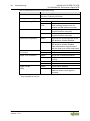
3.6 Technical Data ..................................................................................... 21
3.6.1 Device Data ..................................................................................... 21
3.6.2 Power Supply ................................................................................... 21
3.6.3 Communication ................................................................................ 22
3.6.4 Connection Type .............................................................................. 22
3.6.5 Mechanical Conditions ..................................................................... 22
3.6.6 Climatic Environmental Conditions ................................................... 23
3.7 Approvals ............................................................................................. 24
3.8 Standards and Guidelines .................................................................... 25
4 Process Image ......................................................................................... 31
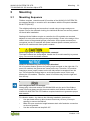
5 Mounting .................................................................................................. 33
5.1 Mounting Sequence .............................................................................. 33
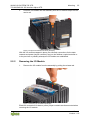
5.2 Inserting and Removing Devices .......................................................... 34
5.2.1 Inserting the I/O Module ................................................................... 34
5.2.2 Removing the I/O Module ................................................................ 35

4 Table of Contents WAGO-I/O-SYSTEM 750 XTR
750-630/040-001 SSI Interface Adjust XTR
Manual
Version 1.1.0
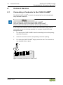
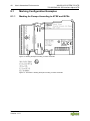
6 Connect Devices ..................................................................................... 36
6.1 Connecting a Conductor to the CAGE CLAMP
®
................................... 36
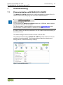
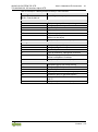
7 Commissioning ....................................................................................... 37
7.1 Parameterization with WAGO-I/O-CHECK ............................................ 37
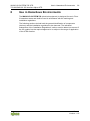
8 Use in Hazardous Environments ........................................................... 39
8.1 Marking Configuration Examples .......................................................... 40
8.1.1 Marking for Europe According to ATEX and IECEx .......................... 40
8.1.2 Marking for the United States of America (NEC) and Canada
(CEC) ............................................................................................... 44
8.2 Installation Regulations......................................................................... 47
8.2.1 Special Notes Regarding Explosion Protection ................................ 47
8.2.2 Special Notes Regarding ANSI/ISA Ex ............................................ 49
List of Figures .................................................................................................. 50
List of Tables .................................................................................................... 51
=== Ende der Lis te f ür T e xtmar ke V erz eic hnis _vor ne == =

WAGO-I/O-SYSTEM 750 XTR Notes about this Documentation 5
750-630/040-001 SSI Interface Adjust XTR
Manual
Version 1.1.0
Pos: 7 /A lle Ser ien ( All ge mein e M odul e)/ Über sc hrif ten/ Ebe ne 1/Hi nwei s e zu dies er D o kume ntati on - Über schr ift 1 @ 4\mod_1237987661750_21.docx @ 29029 @ 1 @ 1
1 Notes about this Documentation
Pos: 8 /A lle Ser ien ( All ge mein e M odul e)/ Sic herh eits - und sonstige Hinweise/Hinweis/Hinweis: Dokumentation aufbewahren @ 4\mod_1237987339812_21.docx @ 29026 @ @ 1
Always retain this documentation!
This documentation is part of the product. Therefore, retain the documentation
during the entire service life of the product. Pass on the documentation to any
subsequent user. In addition, ensure that any supplement to this documentation
is included, if necessary.
Pos: 9 /A lle Ser ien ( All ge mein e M odul e)/ Über sc hrif ten/ Ebe ne 2/G ültig kei tsb ereic h - Über schr ift 2 @ 12\mod_1338912448776_21.doc x @ 96469 @ 2 @ 1
1.1 Validity of this Documentation
Pos: 10 /S eri e 7 50 ( WA GO-I/ O-SYST EM) /Hi n weis e zur D okum ent ati on ( alt e Str uktur )/ Gül tig keits ber eic h/G ülti g keitsb erei ch D o kume ntat ion I/ O-Modul 750-xxxx, ohne Var iant enang abe @ 14\ mod_1358944037947_21.docx @ 109346 @ @ 1
This documentation is only applicable to the I/O module 750-630/040-001
(SSI Interface Adjust XTR).
Pos: 11 /S eri e 7 50 ( WA GO-I/O-S YST EM) /Hi n weise z ur Do kum ent ati on (al te Stru ktur )/H in weis e/Ac ht ung: Hi nwei s z ur D oku me ntati on I/O-M odul e 750-xxxx/0 40-000 @ 27 \mod_1468502299549_21.docx @ 216892 @ @ 1
The I/O module 750-630/040-001 shall only be installed and operated according
to the instructions in this manual, in the system description for the WAGO-I/O-
SYSTEM 750 XTR and in the manual for the used fieldbus coupler/controller.
Consider power layout of the WAGO-I/O-SYSTEM 750 XTR!
In addition to these operating instructions, you will also need the system
description “Design Notes XTR – Guidelines and Recommendations for
Increasing Operational Safety” and the manual for the used fieldbus
coupler/controller, which can be downloaded at www.wago.com
. There, you can
obtain important information including information on electrical isolation, system
power and supply specifications.
Pos: 12.1 /All e Seri en ( All ge meine Mo dul e)/Ü bers chr ift en/ Ebe ne 2/ Ur heb ersc hut z - Ü bersc hri ft 2 @ 2 3\mod_1435647042188_21.docx @ 184808 @ 2 @ 1
1.2 Copyright
Pos: 12.2 /All e Seri en ( All ge meine Mo dul e)/R ec htli ches , All ge mei nes /Ur heb ersc hut z au sf ührli ch @ 4\mod_1235565145234_21.docx @ 27691 @ @ 1
This Manual, including all figures and illustrations, is copyright-protected. Any
further use of this Manual by third parties that violate pertinent copyright
provisions is prohibited. Reproduction, translation, electronic and phototechnical
filing/archiving (e.g., photocopying) as well as any amendments require the
written consent of WAGO Kontakttechnik GmbH & Co. KG, Minden, Germany.
Non-observance will involve the right to assert damage claims.
Pos: 12.3 /Dokumentation allgemei n/Gliederungselemente/---Seitenwechsel--- @ 3\mod_1221108045078_0.docx @ 21810 @ @ 1

6 Notes about this Documentation WAGO-I/O-SYSTEM 750 XTR
750-630/040-001 SSI Interface Adjust XTR
Manual
Version 1.1.0
Pos: 12.4 /All e Seri en ( All ge meine Mo dul e)/Ü bers chr ift en/ Ebe ne 2/ S ymbol e - Ü ber schr if t 2 @ 13\ mod_1351068042408_21.docx @ 105270 @ 2 @ 1
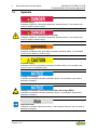
1.3 Symbols
Pos: 12 .5.1 /Al le Seri en (All gemei ne Mod ule)/ Sicher hei ts- u nd s ons tig e Hi nwei se/ Gef ahr/ Gef ahr : _ War nung vor Per son ens chä den all ge mein _ - Er läuter ung @ 13 \mod_1343309450020_21.docx @ 101029 @ @ 1
Personal Injury!
Indicates a high-risk, imminently hazardous situation which, if not avoided, will
result in death or serious injury.
Pos: 12 .5.2 /Al le Seri en (All gemei ne Mod ule)/ Sicher heits- und sonsti ge Hin weise/ Gefa hr/Gef ahr: _ Warnu ng vor Per son ensch äden d urch ele ktrisc hen Str om_ - Erläuterung @ 13\mod_1343309694914_21.doc x @ 101030 @ @ 1
Personal Injury Caused by Electric Current!
Indicates a high-risk, imminently hazardous situation which, if not avoided, will
result in death or serious injury.
Pos: 12 .5.3 /Al le Seri en (All gemei ne Mod ule)/ Sicher heits- und sonstige Hin weise/ Warnung /W arnung: _Warn ung vor P erso nensc häde n allgem ein_ - Erläuterung @ 13\mod_1343309877041_21.doc x @ 101035 @ @ 1
Personal Injury!
Indicates a moderate-risk, potentially hazardous situation which, if not avoided,
could result in death or serious injury.
Pos: 12 .5.4 /Al le Seri en (All gemei ne Mod ule)/ Sicher heits- und sonsti ge Hin weise/ Vorsic ht/V orsic ht: _War nung vor Pers one nschäd en allg emein _ - Erläuterung @ 13\mod_1343310028762_21.docx @ 101038 @ @ 1
Personal Injury!
Indicates a low-risk, potentially hazardous situation which, if not avoided, may
result in minor or moderate injury.
Pos: 12 .5.5 /Al le Seri en (All gemei ne Mod ule)/ Sicher heits- und so nsti ge H in weis e/A chtu ng/ Ach tung : _ War nung v or Sac hsc h äden allg em ein _ - Er läut eru ng @ 13\mod_1343310134623_21.docx @ 101041 @ @ 1
Damage to Property!
Indicates a potentially hazardous situation which, if not avoided, may result in
damage to property.
Pos: 12 .5.6 /Al le Seri en (All gemei ne Mod ule)/ Sicher heits- und sonstige Hin weise/ Achtu ng/Ach tung : _Warnu ng vor Sachsc häden durch el ektros tatis che Au fladu ng_ - Erl äuter ung @ 13\ mod_1343310227702_21.docx @ 101044 @ @ 1
Damage to Property Caused by Electrostatic Discharge (ESD)!
Indicates a potentially hazardous situation which, if not avoided, may result in
damage to property.
Pos: 12 .5.7 /Al le Seri en (All gemei ne Mod ule)/ Sicher heits- und sonstige Hinweise/Hinweis/Hinweis: _Wichtiger Hinweis allgemein_ - Erläuterung @ 13\mod_1343310326906_21.docx @ 101047 @ @ 1
Important Note!
Indicates a potential malfunction which, if not avoided, however, will not result in
damage to property.
Pos: 12 .5.8 /Al le Seri en (All gemei ne Mod ule)/ Sicher heits- und so nsti ge H in weis e/I nfor mat ion/ Inf or mati on: _W eiter e I nfor mat ion all ge mein_ - Erl äuter ung @ 13 \mod_1343310439814_21.doc x @ 101051 @ @ 1

WAGO-I/O-SYSTEM 750 XTR Notes about this Documentation 7
750-630/040-001 SSI Interface Adjust XTR
Manual
Version 1.1.0
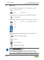
Additional Information:
Refers to additional information which is not an integral part of this
documentation (e.g., the Internet).
Pos: 12.6 /Dokumentation allge mein/ Gli eder ungs ele ment e/---Seit en wechs el--- @ 3\mod_1221108045078_0.docx @ 21810 @ @ 1
Pos: 12.7 /All e Seri en ( All ge meine Mo dul e)/Ü bers chr ift en/ Ebe ne 2/ Dar st ellu ng der Z ahl ens yst eme - Über sc hrift 2 @ 2 3\mod_1435647128078_21.docx @ 184811 @ 2 @ 1
1.4 Number Notation
Pos: 12.8 /All e Seri en ( All ge meine Mo dul e)/R ec htli ches , All ge mei nes /Za hlens ys te me @ 3\mod_1221059454015_21.doc x @ 21711 @ @ 1
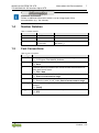
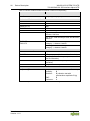
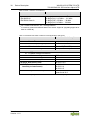
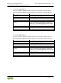
Table 1: Number Notation
Number Code
Example
Note
Decimal
100
Normal notation
Hexadecimal
0x64
C notation
Binary
'100'
'0110.0100'
In quotation marks, nibble separated
with dots (.)
Pos: 12.9 /All e Seri en ( All ge meine Mo dul e)/Ü bers chr ift en/ Ebe ne 2/ Sc hri ftk on venti one n - Ü bersc hri ft 2 @ 23\mod_1435647186005_21.docx @ 184814 @ 2 @ 1
1.5 Font Conventions
Pos: 12.1 0 / Alle Ser ie n (All ge mein e M odul e) /Re chtl ich es, Allg em ein es/Sc hr ift konv enti onen @ 3\mod_1221059521437_21.doc x @ 21714 @ @ 1
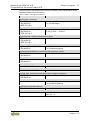
Table 2: Font Conventions
Font Type
Indicates
italic
Names of paths and data files are marked in italic-type.
e.g.: C:\Program Files\WAGO Software
Menu
Menu items are marked in bold letters.
e.g.: Save
>
A greater-than sign between two names means the selection of a
menu item from a menu.
e.g.:
File
>
New
Input
Designation of input or optional fields are marked in bold letters,
e.g.:
Start of measurement range
“Value”
Input or selective values are marked in inverted commas.
e.g.: Enter the value “4 mA” under Start of measurement range.
[Button]
Pushbuttons in dialog boxes are marked with bold letters in square
brackets.
e.g.:
[Input]
[Key]
Keys are marked with bold letters in square brackets.
e.g.:
[F5]
Pos: 13 /Doku ment ation all gemei n/Gli eder ungsel eme nte/---Seit en wechs el--- @ 3\mod_1221108045078 _0. doc x @ 2 181 0 @ @ 1

8 Important Notes WAGO-I/O-SYSTEM 750 XTR
750-630/040-001 SSI Interface Adjust XTR
Manual
Version 1.1.0
Pos: 14 /A ll e Ser ien (Al lg emei ne M od ule)/ Üb ers chrif te n/Eb ene 1/Wi cht ige Erl äu ter unge n - Ü bersc hrift 1 @ 4\mod_1241428899156_21.docx @ 32170 @ 1 @ 1
2 Important Notes
Pos: 15.1 /All e Seri en ( All ge meine Mo dul e)/R ec htli ches , All ge mei nes /Wi chtig e Er l äuter ung en - Ei nleit ung @ 3\mod_1221059818031_21.docx @ 21717 @ @ 1
This section includes an overall summary of the most important safety
requirements and notes that are mentioned in each individual section. To protect
your health and prevent damage to devices as well, it is imperative to read and
carefully follow the safety guidelines.
Pos: 15.2 /All e Seri en ( All ge meine Mo dul e)/Ü bers chr ift en/ Ebe ne 2/ Rec htl ic he Gr un dlag en - Über schri ft 2 @ 3\mod_1221060626343_21.docx @ 21726 @ 2 @ 1
2.1 Legal Bases
Pos: 15.3 /All e Seri en ( All ge meine Mo dul e)/R ec htli ches , All ge mei nes /Änd er ungs vor beh alt - Über schr ift 3 und In halt @ 3\mod_1221060036484_21.docx @ 21720 @ 3 @ 1
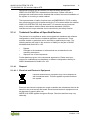
2.1.1 Subject to Changes
WAGO Kontakttechnik GmbH & Co. KG reserves the right to provide for any
alterations or modifications. WAGO Kontakttechnik GmbH & Co. KG owns all
rights arising from the granting of patents or from the legal protection of utility
patents. Third-party products are always mentioned without any reference to
patent rights. Thus, the existence of such rights cannot be excluded.
Pos: 15.4 /Serie 750 (WAGO-I/O-SYST EM) /Wic htige Er läuter unge n (alte Str ukt ur)/P erson alqu alifi kation/ Pers onalqu alifi katio n 750-xxxx - Ü ber schr ift 3 u nd I nh alt @ 3\ mod_ 1224061208046_21.docx @ 24063 @ 3 @ 1
2.1.2 Personnel Qualifications
All sequences implemented on WAGO-I/O-SYSTEM 750 devices may only be
carried out by electrical specialists with sufficient knowledge in automation. The
specialists must be familiar with the current norms and guidelines for the devices
and automated environments.
All changes to the coupler or controller should always be carried out by qualified
personnel with sufficient skills in PLC programming.
Pos: nul l /Ser ie 750 (W AGO-I/ O-SYST EM)/ Wichtig e Erläuter ung en (al te Str ukt ur)/B esti m mungs ge mäß e Ver w endu ng/ Bes timm ung sg emäß e V erwe ndu ng 7 50- xxxx - Überschrift 3 @ 32\mod_1536041141528_21.docx @ 498494 @ 3 @ 1
2.1.3 Use of the 750 Series in Compliance with Underlying
Provisions
Pos: 15.6 /Serie 750 (WAGO-I/O-SYST EM) /Wi cht ige Erl äut eru nge n (al te Str uktur )/B esti mm ungs g emäß e Ver w end ung/ Best im mung sge mäß e V erwe ndu ng 7 50- xxx x für Gerät e - STD - mit EN 61000-6-3 @ 3\ mod_1224064151234_21.docx @ 24070 @ @ 1
Fieldbus couplers, controllers and I/O modules found in the modular WAGO-I/O-
SYSTEM 750 receive digital and analog signals from sensors and transmit them
to actuators or higher-level control systems. Using controllers, the signals can
also be (pre-) processed.
The devices have been developed for use in an environment that meets the IP20
protection class criteria. Protection against finger injury and solid impurities up to
12.5 mm diameter is assured; protection against water damage is not ensured.
Unless otherwise specified, operation of the devices in wet and dusty
environments is prohibited.
Operating the WAGO-I/O-SYSTEM 750 devices in home applications without
further measures is only permitted if they meet the emission limits (emissions of
interference) according to EN 61000-6-3. You will find the relevant information in
the section “Device Description” > “Standards and Guidelines” in the manual for
the used fieldbus coupler or controller.

WAGO-I/O-SYSTEM 750 XTR Important Notes 9
750-630/040-001 SSI Interface Adjust XTR
Manual
Version 1.1.0
Appropriate housing (per 2014/34/EU) is required when operating the
WAGO-I/O-SYSTEM 750 in hazardous environments. Please note that a
prototype test certificate must be obtained that confirms the correct installation of
the system in a housing or switch cabinet.
The implementation of safety functions such as EMERGENCY STOP or safety
door monitoring must only be performed by the F I/O modules within the modular
WAGO-I/O-SYSTEM 750. Only these safe F I/O modules ensure functional
safety in accordance with the latest international standards. WAGO's
interference-free output modules can be controlled by the safety function.
Pos: 15 .7 /All e Ser i en (A llg emei ne M od ule) /R echtl ich es, Allg em ei nes/T ech nisc her Zus ta nd d er Ger äte - Ü bers chr ift 3 u nd I nhal t @ 3\mod_1221060446109_21.docx @ 21723 @ 3 @ 1
2.1.4 Technical Condition of Specified Devices
The devices to be supplied ex works are equipped with hardware and software
configurations, which meet the individual application requirements. These
modules contain no parts that can be serviced or repaired by the user. The
following actions will result in the exclusion of liability on the part of WAGO
Kontakttechnik GmbH & Co. KG:
• Repairs,
• Changes to the hardware or software that are not described in the
operating instructions,
• Improper use of the components.
Further details are given in the contractual agreements. Please send your
request for modified and new hardware or software configurations directly to
WAGO Kontakttechnik GmbH & Co. KG.
Pos: null /Al le S eri en ( All gem eine Mo dul e)/Ü bers chr ift en/E b ene 4/En ts orgen - Üb ersc hrift 4 @ 30 \mod_1510145115652_21.docx @ 469859 @ 4 @ 1
2.1.4.1 Disposal
Pos: nul l /Alle Ser ie n ( Allg emei ne M odul e) /Ü bersc hri fte n/E ben e 5/ Ele ktro- und El ektro nikger äte - Ü bersc hr ift 5 @ 32\ mod_1537446988068_21.docx @ 501657 @ 5 @ 1
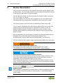
2.1.4.1.1 Electrical and Electronic Equipment
Pos: null /Al le S eri en ( All gem eine Mo dul e)/R ech tli ches , Allgemeines/Elektro- und Elektr onikger äte @ 32\mod_1532425086061_21.docx @ 491989 @ @ 1
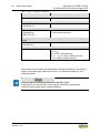
Electrical and electronic equipment may not be disposed of
with household waste. This also applies to products without
this symbol.
Electrical and electronic equipment contain materials and substances that can be
harmful to the environment and health. Electrical and electronic equipment must
be disposed of properly after use.
WEEE 2012/19/EU applies throughout Europe. Directives and laws may vary
nationally.

10 Important Notes WAGO-I/O-SYSTEM 750 XTR
750-630/040-001 SSI Interface Adjust XTR
Manual
Version 1.1.0
Environmentally friendly disposal benefits health and protects
the environment from harmful substances in electrical and
electronic equipment.
• Observe national and local regulations for the disposal of electrical and
electronic equipment.
• Clear any data stored on the electrical and electronic equipment.
• Remove any added battery or memory card in the electrical and
electronic equipment.
• Have the electrical and electronic equipment sent to your local
collection point.
Improper disposal of electrical and electronic equipment can be harmful to the
environment and human health.
Pos: nul l /Dok umen tatio n allge mein/Gl ieder ungs elem ente/----L eerz eile-( 1Z) ---- @ 28\mod_1485262995837_0.doc x @ 404006 @ @ 1
Pos: null /Al le S eri en ( All gem eine Mo dul e)/Ü bers chr ift en/E bene 5/ Verpa ckung - Übersc hrif t 5 @ 3 2\mod_1537447044202_21.doc x @ 501662 @ 5 @ 1
2.1.4.1.2 Packaging
Pos: null /Al le S eri en ( All gem eine Mo dul e)/R ech tli ches , Al lge mei nes/ Ver pac kung @ 32\mod_1537446786416_21.docx @ 501653 @ @ 1
Packaging contains materials that can be reused.
PPWD 94/62/EU and 2004/12/EU packaging guidelines apply throughout
Europe. Directives and laws may vary nationally.
Environmentally friendly disposal of the packaging protects the environment and
allows sustainable and efficient use of resources.
• Observe national and local regulations for the disposal of packaging.
• Dispose of packaging of all types that allows a high level of recovery,
reuse and recycling.
Improper disposal of packaging can be harmful to the environment and wastes
valuable resources.
Pos: 15.1 0 /D ok um entati o n allg em ein/ Gli eder ung sel eme nte/---S eit enw echs el--- @ 3\ mod_1221108045078_0.docx @ 21810 @ @ 1

WAGO-I/O-SYSTEM 750 XTR Important Notes 11
750-630/040-001 SSI Interface Adjust XTR
Manual
Version 1.1.0
Pos: 15.1 1 / Alle Ser ie n (All ge mein e M odul e)/Üb erschr iften /Eben e 2/Sic herh eitshi nweis e - Übers chr ift 2 @ 6\mod_1260180299987_21.doc x @ 46724 @ 2 @ 1
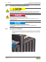
2.2 Safety Advice (Precautions)
Pos: 15.1 2 / Alle Ser ie n (All ge mein e M odul e) /Sic her hei ts- un d s onsti ge Hin wei se/E inl ei tung Sic her heit shi nw eise Har dwar e @ 6\mod_1260180170493_21.docx @ 46720 @ @ 1
For installing and operating purposes of the relevant device to your system the
following safety precautions shall be observed:
Pos: 15.1 3. 1 /Al le S eri en ( Allg em ein e Mo dul e)/Si ch erh eits- und sonstige Hinweis e/G efa hr/G ef ahr: Nich t an G erät en unter S pann ung ar beit en! @ 6\ mod_1260180365327_21.docx @ 46727 @ @ 1
Do not work on devices while energized!
All power sources to the device shall be switched off prior to performing any
installation, repair or maintenance work.
Pos: null /Al le S eri en ( All gem eine Mo dul e)/ Sich erh eits- und so nstig e H inw eis e/G efa hr/G efahr : Pr od uk t nur in ein em g eeig net en Geh äuse ei nba uen! @ 33\mod_1543581881435_21.docx @ 511972 @ @ 1
Install device in only one suitable enclosure!
The device is an open system. Install the device in a suitable enclosure. This
enclosure must:
• Guarantee that the max. permissible degree of pollution is not exceeded.
• Offer adequate protection against contact.
• Prevent fire from spreading outside of the enclosure.
• Offer adequate protection against UV irradiation.
• Guarantee mechanical stability
• Restrict access to authorized personnel and may only be opened with tools
Pos: null /Al le S eri en ( All gem eine Mo dul e)/ Sich erh eits- und sons tig e Hi nw eis e/Gef ahr /G efahr : Tr en nvorr ic ht ung und Ü ber stro ms chutz @ 33\ mod_1543915978439_21.docx @ 512267 @ @ 1
Ensure disconnect and overcurrent protection!
The device is intended for installation in automation technology systems.
Disconnect protection is not integrated. Connected systems must be protected by
a fuse.
Provide suitable disconnect and overcurrent protection on the system side!
Pos: 15.1 3. 4 /Al le S eri en ( Allg em ein e Mo dul e)/Si ch erh eits- und s o nstig e H inw eise /G efa hr/G efahr : U nfal l verh ütung s vorsc hri ft en b each ten! @ 6\mod_1260180657000_21.docx @ 46735 @ @ 1
s: 15. 13. 5 / Alle Ser ie n (All ge mein e M odul e) /Sic her hei ts- un d s onst ige Hi nwei se/ Gef ahr/ Gefa hr: A uf n ormg erec ht en A nsc hlu ss ac hte n! @ 6\mod_1260180753479_21.docx @ 46739 @ @ 1
Ensure a standard connection!
To minimize any hazardous situations resulting in personal injury or to avoid
failures in your system, the data and power supply lines shall be installed
according to standards, with careful attention given to ensuring the correct
terminal assignment. Always adhere to the EMC directives applicable to your
application.
Pos: 15.1 4 / Ser ie 7 50 ( WAG O-I/ O-SYST EM )/ Wichti g e Erl äuter ung en (al te Stru kt ur)/S ic herhei ts - un d son sti ge Hi n weis e/W arn ung /War nu ng: Spei sung aus schl ießlich aus SELV-/PELV- Vers org ung ( 24V- XTR-I /O-M odule) @ 29\mod_1493107132163_21.docx @ 419618 @ @ 1
Power from SELV/PELV power supply only!
All field signals and field supplies connected to this XTR I/O module
(750-630/040-001) must be powered from SELV/PELV power supply(s)!
Pos: 15.1 5 / Alle Ser ie n (All ge mein e M odul e) /Sic her hei ts- un d s onsti ge Hin wei se/V ors ic ht/Vor sic ht : H eiße Ober fl äc he nic ht ber ühre n! (all ge mein) @ 6\mod_1264428115588_21.doc x @ 48610 @ @ 1

12 Important Notes WAGO-I/O-SYSTEM 750 XTR
750-630/040-001 SSI Interface Adjust XTR
Manual
Version 1.1.0
Do not touch hot surfaces!
The surface of the housing can become hot during operation. If the device was
operated at high ambient temperatures, allow it to cool off before touching it.
Pos: nul l /Ser ie 750 (W AGO-I/ O-SYST EM) /Wich tige Er läuter ungen (alte Str ukt ur)/Sic her heits- u nd s ons tig e Hi nw eise /Ac htung /Ac ht ung: Ei nwa ndfr eie Kont a ktier ung zur Trag sc hie ne g ew ährl eist en! @ 3 4\mod_1550481407638_21.doc x @ 530599 @ @ 1
Ensure proper contact with the DIN-rail!
Proper electrical contact between the DIN-rail and device is necessary to
maintain the EMC characteristics and function of the device.
Pos: 15.1 6. 2 /Al le S eri en ( Allg em ein e Mo dul e)/Si ch erh eits- und s o nstig e H inw eise /Ac htu ng/Ac ht ung : D efe kte oder bes chädi gt e G erät e austa usc hen! @ 6\ mod_1260180857358_21.doc x @ 46743 @ @ 1
Replace defective or damaged devices!
Replace defective or damaged device/module (e.g., in the event of deformed
contacts).
Pos: 15.1 6. 3 /Al le S eri en ( Allg em ein e Mo dul e)/Si ch erh eits- und s o nstig e H inw eise /A chtu ng/A cht ung : G erät e vor kriec hen den und isol i ere nden Sto ffen sc hütz en! @ 6\ mod_1260181036216_21.docx @ 46747 @ @ 1
Protect the components against materials having seeping and insulating
properties!
The components are not resistant to materials having seeping and insulating
properties such as: aerosols, silicones and triglycerides (found in some hand
creams). If you cannot exclude that such materials will appear in the component
environment, then install the components in an enclosure being resistant to the
above-mentioned materials. Clean tools and materials are imperative for
handling devices/modules.
Pos: 15.1 6. 4 /Al le S eri en ( Allg em ein e Mo dul e)/Si ch erh eits- und s o nstig e H inw eise /Ac htu ng/Ac ht ung : R einig ung nur mi t zul äss ige n M ater ial ien! @ 6\mod_1260181203293_21.doc x @ 46751 @ @ 1
Clean only with permitted materials!
Clean housing and soiled contacts with propanol.
Pos: 15.1 6. 5 /Al le S eri en ( Allg em ein e Mo dul e)/Si ch erhei ts- und sonstige Hinweise/Achtung/Achtung: Kein Kontaktspray verwenden! @ 6\mod_1260181290808_21.docx @ 46755 @ @ 1
Do not use any contact spray!
Do not use any contact spray. The spray may impair contact area functionality in
connection with contamination.
Pos: 15.1 6. 6 /Al le S eri en ( Allg em ein e Mo dul e)/Si ch erh eits- und s o nstig e H inw eise /A chtu ng/A cht ung : V erpol ung en der Dat en- und V ersorg ungsl eitu ngen ver meide n! @ 6\mod_1260184045744_21.doc x @ 46767 @ @ 1
Do not reverse the polarity of connection lines!
Avoid reverse polarity of data and power supply lines, as this may damage the
devices involved.
Pos: 15.1 6. 7 /Al le S eri en ( Allg em ein e Mo dul e)/Si ch erh eits- und sonstige Hinweise/Achtung/Achtung: Elektrostatische Entladung vermei de n! - DIN EN 61340-5-1/-3 @ 6\ mod_1260181364729_21.docx @ 46759 @ @ 1

WAGO-I/O-SYSTEM 750 XTR Important Notes 13
750-630/040-001 SSI Interface Adjust XTR
Manual
Version 1.1.0
Avoid electrostatic discharge!
The devices are equipped with electronic components that may be destroyed by
electrostatic discharge when touched. Please observe the safety precautions
against electrostatic discharge per DIN EN 61340-5-1/-3. When handling the
devices, please ensure that environmental factors (personnel, work space and
packaging) are properly grounded.
Pos: 15.1 7 / Ser ie 7 50 ( WAG O-I/ O-SYST EM) /Wichti g e Erl äuter ung en (alt e St ruk tur )/Si cher hei ts- und s on stig e Hi nwei se/ Ac htung /Ac ht ung: XTR - Is olati onspr üfung en mit DC d urch führe n! @ 15\mod_1370843209441_21.doc x @ 122210 @ @ 1
Use only direct current (DC) for insulation testing!
Both the system voltage and field voltage side are capacitively coupled to the
DIN-rail. If an I/O module is mounted on the DIN-rail, application of an AC voltage
between the DIN-rail and at least one of these two potentials can lead to the
destruction of the module.
Use only direct current (DC) for insulation testing. To avoid destroying the I/O
module, you must discharge it completely before applying the test voltage again.
Pos: 16 /Doku ment ation all gemei n/Gli eder ungsel eme nte/---Seit en wechs el--- @ 3\mod_1221108045078_0.doc x @ 21810 @ @ 1

14 Device Description WAGO-I/O-SYSTEM 750 XTR
750-630/040-001 SSI Interface Adjust XTR
Manual
Version 1.1.0
Pos: 17 /A ll e Ser ien (Al lg emei ne M od ule)/ Üb ers chrif te n/Eb ene 1/G erät e besc hrei bung - Ü ber schri ft 1 @ 3\mod_1233756084656_21.docx @ 27096 @ 1 @ 1
3 Device Description
Pos: 18.1 .1 /Ser ie 7 50 ( WAG O-I/ O-SYST EM )/G erä teb esc hrei bu ng (al te Struktur)/Einleitung/Anwendung/S O/Anwendung 750-063 0/04 0-001 @ 30\mod_1506437410532_21.docx @ 462408 @ @ 1
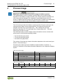
The I/O module functions as an SSI interface and outputs a pulse signal to read
out the encoder. The I/O module reads the incoming data and transmits it directly
in the form of a data word in the process image.
Pos: 18.1 .2 /Ser ie 7 50 ( WAG O-I/ O-SYST EM )/G erä teb esc hrei bu ng (al te Str ukt ur) /Ei nleit ung /I/ O-Bes chr eibu ng/S O/I /O-B eschr eibung 750-06 30 @ 9\m od_ 1290755754387_21.doc x @ 66883 @ @ 1
The SSI absolute encoder can be connected to the CAGE CLAMP
®
connectors
+D, −D, +CL and −CL directly.
The power supply for the encoder can be tapped from the I/O module directly.
Pos: 18.1 .3 /Ser ie 7 50 ( WAG O-I/ O-SYST EM) /Ger äte bes chr ei bung (alt e St ru ktur )/Ei nlei tu ng/I /O-B eschr eibu ng/All gemei n/Ver weis auf Kapit el "An schlüs se" @ 8\ mod_1276775378035_21.docx @ 57956 @ @ 1
The assignment of the connections is described in the “Connectors” section.
Pos: 18.1.4 /Dokumentation allg emei n/ Glie der ungs elem ente /----Leer zeil e-(1Z )---- @ 28\mod_1485262995837_0.docx @ 404006 @ @ 1
Pos: 18.1 .5 /Ser ie 7 50 ( WAG O-I/ O-SYST EM )/G erä teb esc hrei bu ng (al te Str ukt ur) /Ei nleit ung /LED -A nzeig e/LED Zus tan d Betri eb Kle mme @ 14\mod_1359040991238_21.docx @ 1099 21 @ @ 1
The operating status of the I/O module is indicated by a green status LED.
Pos: 18 .1.6 /D okum entati on allg emei n/Glie derung sele mente /----Leerz eil e-(1Z) ---- @ 28\mod_1485262995837_0.docx @ 404006 @ @ 1
Pos: 18.1 .7 /Ser ie 7 50 ( WAG O-I/ O-SYST EM) /Gerä tebes chrei bung (alte Str uktur )/Ei nleitu ng/Ver sorgu ng/V ersor gung 2 4 V, 0 V über Lei stung skont akte St and ard @ 3\mod_1226498974531_21.docx @ 25020 @ @ 1
The I/O module 750-630/040-001 (SSI Interface Adjust XTR) receives the 24 V
voltage supply for the field level from an upstream I/O module or from the
fieldbus coupler/controller via blade-formed power jumper contacts. It then
provides these potentials to subsequent I/O modules via spring-formed power
jumper contacts.
Pos: 18.1 .8 /Ser ie 7 50 ( WAG O-I/ O-SYST EM) /Gerä tebes chrei bung (alte Str uktur )/Ei nleitu ng/Ver sorgu ng/A nord nung un ter Ber ücksic htig ung der L eistung sko ntakt e beliebi g @ 3\ mod_1233756233468_21.docx @ 27 099 @ @ 1
With consideration of the power jumper contacts, the individual modules can be
arranged in any combination when configuring the fieldbus node.
An arrangement in groups within the group of potentials is not necessary.
Pos: 18 .1.9 /S erie 750 (WAGO-I/O-SYST EM) /Ger äte bes chr ei bung (alt e S tr uktur )/Ei nlei tu ng/ Vers org ung /Gal vani sc he Tr en nung F eld/ Sys tem @ 3\ mod_1233756478750_21.docx @ 27102 @ @ 1
The field voltage and the system voltage are electrically isolated from each other.
Pos: 18.1 .10 /Ser ie 750 ( WA GO-I/O- SY STEM )/Wi chti g e Erl äu ter ung en ( alte Str uktur )/ Sic her heit s- un d s onst ige H i nweis e/ Warn ung /War nu ng: Sp eisu ng auss chli eßl ich aus SEL V-/PELV-Versor gung ( 24V- XTR-I /O-M odule) @ 29 \mod_1493107132163_21.docx @ 419618 @ @ 1
Power from SELV/PELV power supply only!
All field signals and field supplies connected to this XTR I/O module
(750-630/040-001) must be powered from SELV/PELV power supply(s)!
Pos: 18.1 .1 1 /S erie 750 ( W AGO -I/O-SY ST EM)/Wic htig e Erl äu ter ung en ( alte Str uktur )/ Sic her heit s- un d s onst ige H i nweis e/ Acht ung/ Ac htung : M axi mal er Str om L eist ung sko nta kte 10 A @ 3\ mod_1226499143500_21.docx @ 25029 @ @ 1
Do not exceed maximum values via power contacts!
The maximum current that can flow through the power jumper contacts is 10 A.
The power jumper contacts can be damaged and the permissible operating
temperature can be exceeded by higher current values.
When configuring the system, do not exceed the permissible maximum current
value. If there is a higher power requirement, you must use an additional supply
module to provide the field voltage.
Pos: 18.1 .1 2 /S erie 750 ( W AGO -I/O-SY ST EM) /Wic htig e Er l äuter ung en (alt e St ruk tur) /Si cher hei ts- und sonstige Hinweise/Hinweis/Hinweis: XTR - Mi sc hbetri eb XT R/St andar d @ 15\mod_1367496420828_21.docx @ 118326 @ @ 1
Mixed operation
Mixed operation (standard/XTR modules) within a node is possible when groups
of modules are electrically isolated on the field side (i.e., electrically isolated
power supply).
Pos: 18.1 .1 3 /S erie 750 ( W AGO -I/O-SY ST EM) /Wic htig e Er l äuter ung en (alt e St ruk tur) /Si cher hei ts- und s ons tig e Hi nwei se/H i nwei s/Hi nw eis: Ei nspei se mod ul f ür g al vanis ch e Tr enn ung der Ver sorg ung ss pann ung (XTR ) @ 30 \mod_1505385137982_21.docx @ 461143 @ @ 1

WAGO-I/O-SYSTEM 750 XTR Device Description 15
750-630/040-001 SSI Interface Adjust XTR
Manual
Version 1.1.0
Use an appropriate supply module!
Use an appropriate supply module (e.g., 750-602/040-000) if an electrically
isolated voltage supply is required!
Pos: 18.1 .1 4 /S erie 750 ( W AGO -I/O-SY ST EM) /Wic htig e Er l äuter ung en (alt e St ruk tur) /Si cher hei ts- und sonstige Hinweise/Hinweis/Hinweis: XTR - Er höht e St örfe sti g keit @ 15\ mod_1367496424993_21.docx @ 118330 @ @ 1
Increased interference!
For standard-compliant application in substation instrumentation and control,
telecontrol systems, railway technology or shipbuilding certified operation,
field-side power supply filter 750-624/040-001 or power supply filter
750-626/040-000 are generally to be used for XTR module groups.
Pos: 18.1 .1 5 /S erie 750 ( W AGO -I/O-SY ST EM) /Ger äte bes chr eib ung ( alt e S tru ktur)/ Einlei tung/ Eins atzber eich/ Eins atzb ereich 75 0-xxxx/04 0-000 al l e XTR -Kop pler /C ontr oll er ohne Ei nsc hrän kung +Mi sc hbetr ie bhin wei se @ 15\ mod_1368425919479_21.docx @ 119444 @ @ 1
The I/O module can be operated with all fieldbus couplers/controllers of the
WAGO-I/O-SYSTEM 750 XTR.
Observe the instructions for mixed operation when used in mixed operation
behind standard fieldbus couplers/controllers.
Pos: 18.2 /Dokumentation allgemei n/Gliederungselemente/---Sei te nwe chsel --- @ 3\mod_1221108045078_0.docx @ 21810 @ @ 1

16 Device Description WAGO-I/O-SYSTEM 750 XTR
750-630/040-001 SSI Interface Adjust XTR
Manual
Version 1.1.0
Pos: 18.3 /All e Seri en ( All ge meine Mo dul e)/Ü bers chr ift en/ Ebe ne 2/ A nsich t - Ü bers chr ift 2 @ 4\mod_1240984217343_21.doc x @ 31958 @ 2 @ 1
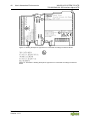
3.1 View
Pos: 18.4 /Serie 750 (WAGO-I/O-SYST EM )/ Ger äteb esc hrei bung (al te Str ukt ur)/ Ansi cht/ FT &K/A nsi cht 750- 063 0/04 0-001 @ 30\mod_1502360732795_21.docx @ 458041 @ @ 1
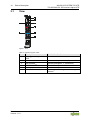
Figure 1: View
Pos: 18.5 /Serie 750 (WAGO-I/O-SYST EM )/ Ger äteb esc hrei bung (al te Str uktur )/Ansi cht/ Ansich t CageC lamp® _Leg ende mi t LEDs , mit 1 Entr iegel ungsl asche @ 15\mod_1370867188922_21.docx @ 122225 @ @ 1
Table 3: Legend for Figure “View”
Pos.
Description
Details See Section
1
Marking possibility with Mini-
WSB
---
2
Status LEDs
“Device Description” > “Display Elements”
3
Data contacts
“Device Description” > “Connectors”
4
CAGE CLAMP
®
connectors
“Device Description” > “Connectors”
5
Power jumper contacts
“Device Description” > “Connectors”
6
Release tab
“Mounting” > “Inserting and Removing
Devices”
Pos: 18.6 /Dokumentation allgemei n/Gliederungselemente/---Sei te nwe chsel --- @ 3\mod_1221108045078_0.docx @ 21810 @ @ 1

WAGO-I/O-SYSTEM 750 XTR Device Description 17
750-630/040-001 SSI Interface Adjust XTR
Manual
Version 1.1.0
Pos: 18.7 /All e Seri en ( All ge meine Mo dul e)/Ü bers chr ift en/ Ebe ne 2/ A nsc hlüss e - Ü ber schr ift 2 @ 4\ mod_1240984262656_21.docx @ 31961 @ 2 @ 1
3.2 Connectors
Pos: 18.8 /Serie 750 (WAGO-I/O-SYST EM )/ Ger äteb esc hrei bung (al te Str ukt ur)/ Ansc hlüs se /Da ten kon takt e/L okal bus - Üb ersc hrif t 3 @ 6 \mod_1256294684083_21.docx @ 43660 @ 3 @ 1
3.2.1 Data Contacts/Local Bus
Pos: 18.9 .1 /Ser ie 7 50 ( WAG O-I/ O-SYST EM )/G erä teb esc hrei bu ng (al te Str ukt ur) /Ansc hlüs se /Da ten kon tak te - Fel d busk oppl er/-c on troll er und Mo dule – Ab bild ung und Bes chr eibu ng @ 3 \mod_1231771259187_21.docx @ 26002 @ @ 1
Communication between the fieldbus coupler/controller and the I/O modules as
well as the system supply of the I/O modules is carried out via the local bus. The
contacting for the local bus consists of 6 data contacts, which are available as
self-cleaning gold spring contacts.
Figure 2: Data Contacts
Pos: 18.9 .2 /Ser ie 7 50 ( WAG O-I/ O-SYST EM) /Wich tige Er läut erunge n (alte Str ukt ur)/Sic her heits- und sonstige Hinweise/Achtung/Achtung: I/O-Mod ule nic ht auf Gol dfeder kont akte leg en! @ 7\mod_1266318463636_21.docx @ 50695 @ @ 1
Do not place the I/O modules on the gold spring contacts!
Do not place the I/O modules on the gold spring contacts in order to avoid soiling
or scratching!
Pos: nul l /Ser ie 750 (W AGO-I/ O-SYST EM) /Wich tige Er läuter ungen (alte Str ukt ur)/Sic her heits- u nd s ons tig e Hi nw eise /Ac htung /Ac ht ung: ESD - Au f Pote ntiala usgl eich der U mgeb ung acht en! @ 32\ mod_1539077262331_21.docx @ 504433 @ @ 1
Pay attention to potential equalization from the environment!
The devices are equipped with electronic components that may be destroyed by
electrostatic discharge. When handling the devices, please ensure that
environmental factors (personnel, work space and packaging) are properly
equalized. Do not touch any conducting parts, e.g., data contacts.
Pos: 18.1 0 /D ok um entati o n allg em ein/ Gli eder ung sel eme nte/---S eit enw echs el--- @ 3\ mod_1221108045078_0.docx @ 21810 @ @ 1

18 Device Description WAGO-I/O-SYSTEM 750 XTR
750-630/040-001 SSI Interface Adjust XTR
Manual
Version 1.1.0
Pos: 18 .11 /S erie 750 ( W AGO- I/O-SY ST EM)/ Ger äte besc hr eibu ng ( alt e Str uk tur)/ An schl üss e/Lei st ung sk onta kte/ Fel dver sorg ung - Ü bersc hr ift 3 @ 6\mod_1256294692864_21.doc x @ 43664 @ 3 @ 1
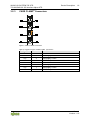
3.2.2 Power Jumper Contacts/Field Supply
Pos: 18.1 2. 1 /S erie 750 ( W AGO -I/O-SY ST EM)/Wic htig e Erl äu ter ung en ( alte Str uktur )/ Sic her heit s- un d s onst ige H i nweis e/ Vor sicht /V orsi cht: V erletz u ngsg efahr d urch sc harf ka ntig e Mes ser k onta kte! @ 6 \mod_1256193279401_21.docx @ 43414 @ @ 1
Risk of injury due to sharp-edged blade contacts!
The blade contacts are sharp-edged. Handle the I/O module carefully to prevent
injury. Do not touch the blade contacts.
Pos: 18.1 2. 2 /S erie 750 ( W AGO -I/O-SY ST EM) /Ger äte bes chr eib ung ( alt e S tru ktur) /An schl üss e/ Leis tung s konta kte 2 L K (M ess er/ Fed er) - Ei nleitung @ 15\mod_1371721641099_21.docx @ 123714 @ @ 1
The I/O module 750-630/040-001 has 2 self-cleaning power jumper contacts that
supply and transmit power for the field side. The contacts on the left side of the
I/O module are designed as blade contacts and those on the right side as spring
contacts.
Pos: 18.1 2. 3 /S erie 750 ( W AGO -I/O-SY ST EM) /Ger äte bes chr eib ung ( alt e S tru ktur) /An schl üss e/ Leis tung s konta kte 2 L K (M ess er/ Fed er) - Abbi ldung , einfac he Br eite - St andar d @ 15\mod_1367500700037_21.docx @ 118396 @ @ 1
Figure 3: Power Jumper Contacts
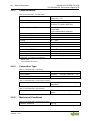
Pos: 18.1 2. 4 /S erie 750 ( W AGO -I/O-SY ST EM) /Ger äte bes chr eib ung ( alt e Struktur)/Anschlüsse/Leistungskontakte 2 LK (Messer/Feder) - Lege nde @ 15\ mod_1371721352500_21.docx @ 123710 @ @ 1
Table 4: Legend for Figure “Power Jumper Contacts”
Contact
Type
Function
1
Spring contact
Potential transmission (U
v
) for field supply
2
Spring contact
Potential transmission (0 V) for field supply
3
Blade contact
Potential feed-in (0 V) for field supply
4
Blade contact
Potential feed-in (U
v
) for field supply
Pos: 18.1 2. 5 /S erie 750 ( W AGO -I/O-SY ST EM)/Wic htig e Erl äu ter ung en ( alte Str uktur )/ Sic her heit s- un d s onst ige H i nweis e/ Acht ung/ Ac htung : M axi mal er Str om L eist ung sko nta kte 10 A @ 3\ mod_1226499143500_21.docx @ 25029 @ @ 1
Do not exceed maximum values via power contacts!
The maximum current that can flow through the power jumper contacts is 10 A.
The power jumper contacts can be damaged and the permissible operating
temperature can be exceeded by higher current values.
When configuring the system, do not exceed the permissible maximum current
value. If there is a higher power requirement, you must use an additional supply
module to provide the field voltage.
Pos: 18.1 3 /D ok um entati o n allg em ein/ Gli eder ung sel eme nte/---S eit enw echs el--- @ 3\ mod_1221108045078_0.docx @ 21810 @ @ 1

WAGO-I/O-SYSTEM 750 XTR Device Description 19
750-630/040-001 SSI Interface Adjust XTR
Manual
Version 1.1.0
Pos: 18 .14 /S erie 750 ( WAG O-I/O-SY ST EM) /Ger äte bes chr eib ung (alt e St ruk tur) /An schl üss e/C AG E CLAM P- Ansc hlüs se - Über schri ft 3 @ 6\mod_1256296337770_21.docx @ 43674 @ 3 @ 1
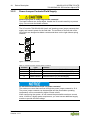
3.2.3 CAGE CLAMP
®
Connectors
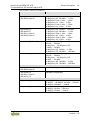
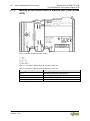
Pos: 18.1 5 / Ser ie 7 50 ( WAG O-I/ O-SYST EM )/G erät ebe schr eib ung (al te Stru ktur )/ Ansc hlüs se/F T& K/A nsc hlü sse C C 750-0630 @ 10\mod_1299070985922_21.docx @ 70364 @ @ 1
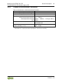
Figure 4: CAGE CLAMP
®
Connectors
Table 5: Legend for Figure “CAGE CLAMP
®
Connectors“
Designation
Connector
Function
+D
1
Data in
24 V
2
Field supply 24 VDC
0 V
3
Field supply 0 VDC
+CL
4
CLOCK output
−D
5
Data in
24 V
6
Field supply 24 VDC
0 V
7
Field supply 0 VDC
−CL
8
CLOCK output
Pos: 18 .16 /D ok ument ati on al lg em ein/G li eder ung sel eme nte/---S eit enwec hs el--- @ 3\ mod_1221108045078_0.docx @ 21810 @ @ 1

20 Device Description WAGO-I/O-SYSTEM 750 XTR
750-630/040-001 SSI Interface Adjust XTR
Manual
Version 1.1.0
Pos: 18.1 7 / Alle Ser ie n (All ge mein e M odul e) /Üb ersc hri ften /Eb ene 2/ Anzei ge ele ment e - Ü bersc hrift 2 @ 4\ mod_1240984390875_21.docx @ 31964 @ 2 @ 1
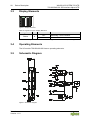
3.3 Display Elements
Pos: 18.1 8 / Ser ie 7 50 ( WAG O-I/ O-SYST EM)/ Gerät ebesc hreib ung (al te Stru ktur)/ Anzei geel ement e/FT &K/Anz eigeel eme nte 750- 063 0/04 0-001 @ 30\mod_1506431195010_21.docx @ 462357 @ @ 1
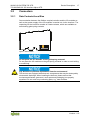
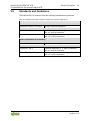
Figure 5: Display Elements
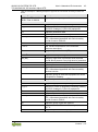
Table 6: Legend for Figure “Display Elements”
Designation
LED
State
Function
Status A
OFF
Watchdog Timer Overflow
*)
Green
Normal mode
*)
If the fieldbus coupler/controller does not transmit any process data for 100 ms, the LED goes out.
Pos: 18.1 9 / Alle Ser ie n (All ge mein e M odul e) /Üb ersc hri ften /Eb ene 2/ Bedie nel em ente - Üb ersc hrift 2 @ 4\ mod_1239191655456_21.docx @ 30439 @ 2 @ 1
3.4 Operating Elements
Pos: 18.2 0 / Ser ie 7 50 ( WAG O-I/ O-SYST EM)/ Gerät ebesc hreib ung (al te Stru ktur)/ Bedi enele ment e/Bedi enel ement e I/O-Mod ul 75 x-xxxx nic ht vor hande n @ 4\mod_1236322031125_21.docx @ 28063 @ @ 1
The I/O module 750-630/040-001 has no operating elements.
Pos: 18.2 1 / Alle Ser ie n (All ge mein e M odul e) /Üb ersc hri ften /Eb ene 2/ Sche mati sc hes S ch alt bild - Ü b erschr if t 2 @ 4 \mod_1240984441312_21.docx @ 31967 @ 2 @ 1
3.5 Schematic Diagram
Pos: 18.2 2 / Ser ie 7 50 ( WAG O-I/ O-SYST EM)/ Gerät ebesc hreib ung (al te Stru ktur)/ Sche matisc he Sch altbi lder/F T&K/ Sche matisc hes Sc haltbi ld 750- 063 0/0 40-00 1 @ 30\mod_1506431045371_21.docx @ 462353 @ @ 1
Figure 6: Schematic Diagram
Pos: 18.2 3 /D ok um entati o n allg em ein/ Gli eder ung sel eme nte/---S eit enw echs el--- @ 3\ mod_1221108045078_0.docx @ 21810 @ @ 1
Page is loading ...
Page is loading ...
Page is loading ...
Page is loading ...
Page is loading ...
Page is loading ...
Page is loading ...
Page is loading ...
Page is loading ...
Page is loading ...
Page is loading ...
Page is loading ...
Page is loading ...
Page is loading ...
Page is loading ...
Page is loading ...
Page is loading ...
Page is loading ...
Page is loading ...
Page is loading ...
Page is loading ...
Page is loading ...
Page is loading ...
Page is loading ...
Page is loading ...
Page is loading ...
Page is loading ...
Page is loading ...
Page is loading ...
Page is loading ...
Page is loading ...
Page is loading ...
-
 1
1
-
 2
2
-
 3
3
-
 4
4
-
 5
5
-
 6
6
-
 7
7
-
 8
8
-
 9
9
-
 10
10
-
 11
11
-
 12
12
-
 13
13
-
 14
14
-
 15
15
-
 16
16
-
 17
17
-
 18
18
-
 19
19
-
 20
20
-
 21
21
-
 22
22
-
 23
23
-
 24
24
-
 25
25
-
 26
26
-
 27
27
-
 28
28
-
 29
29
-
 30
30
-
 31
31
-
 32
32
-
 33
33
-
 34
34
-
 35
35
-
 36
36
-
 37
37
-
 38
38
-
 39
39
-
 40
40
-
 41
41
-
 42
42
-
 43
43
-
 44
44
-
 45
45
-
 46
46
-
 47
47
-
 48
48
-
 49
49
-
 50
50
-
 51
51
-
 52
52


WAGO SSI Interface Adjust /XTR User manual
- Type
- User manual
Ask a question and I''ll find the answer in the document
Finding information in a document is now easier with AI
Related papers
-
WAGO I/O-SYSTEM 750 User manual
-
WAGO ETHERNET TCP/IP Programmable Fieldbus Controller User manual
-
-
-
-
-
-
-
-
Other documents
-
Altec 1606A Operating Instructions Manual
-
Krone XDisc 620 Operating instructions
-
Retsch PT 200 Operating instructions
-
Allen-Bradley C Series Nstallation Instructions
-
-
Krone BA Swadro 1400 Operating instructions
-
 Xantrex XTR 850 Watt User manual
-
Lika SMLAX User manual
-
OPTO 22 SNAP SSI Module User guide
-
STECA 40000 User manual
