
Pos: 2 /Dokumentation allgemein/Einband/Einband Handbuch - Deckbl at t oh ne V aria nt enfel d (S ta ndar d) @ 9 \mod_1285229289866_0.docx @ 64941 @ @ 1
Manual
WAGO-I/O-SYSTEM 750
ETHERNET Controller 10 MBit
750-843
PLC -
ETHERNET TCP/IP Programmable Fieldbus
Controller
Version 1.2.0
Pos: 3 /A lle Ser ien ( All ge mein e M odul e)/ Hin weis e z ur D oku men tati on/I mpr ess um für Sta ndar dh and büch er - al lg. A ngabe n, Ansc hrifte n, Telef onn ummer n und E-Mai l-A dresse n @ 3\mod_1219151118203_21.docx @ 21060 @ @ 1

2 WAGO-I/O-SYSTEM 750
750-843 ETHERNET Controller 10 MBit
Manual
Version 1.2.0
© 2014 by WAGO Kontakttechnik GmbH & Co. KG
All rights reserved.
WAGO Kontakttechnik GmbH & Co. KG
Hansastraße 27
D-32423 Minden
Phone: +49 (0) 571/8 87 – 0
Fax: +49 (0) 571/8 87 – 1 69
Web: http://www.wago.com
Technical Support
Phone: +49 (0) 571/8 87 – 5 55
Fax: +49 (0) 571/8 87 – 85 55
Every conceivable measure has been taken to ensure the accuracy and
completeness of this documentation. However, as errors can never be fully
excluded, we always appreciate any information or suggestions for improving the
documentation.
We wish to point out that the software and hardware terms as well as the
trademarks of companies used and/or mentioned in the present manual are
generally protected by trademark or patent.
=== Ende der Lis te f ür T e xtmar ke Ei nb and _vor ne = ==

WAGO-I/O-SYSTEM 750 Table of Contents 3
750-843 ETHERNET Controller 10 MBit
Manual
Version 1.2.0
Pos: 5 /D ok ument ati on al lg em ein/V erz eic hni sse /Inh alts ver zei chni s - Ü bersc hrift oG und Ver zeich nis @ 3\mod_1219151230875_21.docx @ 21063 @ @ 1
Table of Contents
1 Notes about this Documentation ................................................................. 9
1.1 Validity of this Documentation ................................................................. 9
1.2 Copyright ................................................................................................... 9
1.3 Symbols ................................................................................................... 10
1.4 Number Notation ..................................................................................... 12
1.5 Font Conventions .................................................................................... 12
2 Important Notes ......................................................................................... 13
2.1 Legal Bases ............................................................................................. 13
2.1.1 Subject to Changes ............................................................................. 13
2.1.2 Personnel Qualifications ..................................................................... 13
2.1.3 Use of the WAGO-I/O-SYSTEM 750 in Compliance with Underlying
Provisions ........................................................................................... 13
2.1.4 Technical Condition of Specified Devices ......................................... 14
2.2 Safety Advice (Precautions) .................................................................... 15
2.3 Special Use Conditions for ETHERNET Devices .................................. 17
3 System Description..................................................................................... 18
3.1 Manufacturing Number ........................................................................... 19
3.2 Hardware Address (MAC ID) ................................................................. 19
3.3 Component Update .................................................................................. 20
3.4 Storage, Assembly and Transport ........................................................... 20
3.5 Assembly Guidelines/Standards .............................................................. 21
3.6 Power Supply .......................................................................................... 22
3.6.1 Isolation .............................................................................................. 22
3.6.2 System Supply .................................................................................... 23
3.6.2.1 Connection ..................................................................................... 23
3.6.2.2 Dimensioning ................................................................................. 24
3.6.3 Field Supply........................................................................................ 27
3.6.3.1 Connection ..................................................................................... 27
3.6.3.2 Fusing ............................................................................................ 29
3.6.4 Supplementary Power Supply Regulations ........................................ 32
3.6.5 Supply Example.................................................................................. 33
3.6.6 Power Supply Unit ............................................................................. 35
3.7 Grounding ............................................................................................... 36
3.7.1 Grounding the DIN Rail ..................................................................... 36
3.7.1.1 Framework Assembly .................................................................... 36
3.7.1.2 Insulated Assembly ........................................................................ 36
3.7.2 Grounding Function............................................................................ 37
3.8 Shielding ................................................................................................. 38
3.8.1 General ............................................................................................... 38
3.8.2 Bus Cables .......................................................................................... 38
3.8.3 Signal Lines ........................................................................................ 39
3.8.4 WAGO Shield Connecting System .................................................... 39
4 Device Description ..................................................................................... 40
4.1 View ........................................................................................................ 42
4.2 Connectors ............................................................................................... 44

4 Table of Contents WAGO-I/O-SYSTEM 750
750-843 ETHERNET Controller 10 MBit
Manual
Version 1.2.0
4.2.1 Device Supply .................................................................................... 44
4.2.2 Fieldbus Connection ........................................................................... 44
4.3 Display Elements .................................................................................... 46
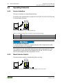
4.4 Operating Elements ................................................................................. 48
4.4.1 Service Interface ................................................................................. 48
4.4.2 Mode Selector Switch......................................................................... 48
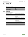
4.5 Technical Data ........................................................................................ 51
4.5.1 Device Data ........................................................................................ 51
4.5.2 System Data ........................................................................................ 51
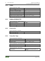
4.5.3 Supply ................................................................................................. 52
4.5.4 Fieldbus MODBUS/TCP .................................................................... 52
4.5.5 Accessories ......................................................................................... 52
4.5.6 Connection Type ................................................................................ 52
4.5.7 Climatic Environmental Conditions ................................................... 53
4.5.8 Mechanical Strength acc. to IEC 61131-2 .......................................... 53
4.6 Approvals ................................................................................................ 54
4.7 Standards and Guidelines ........................................................................ 56
5 Mounting ..................................................................................................... 57
5.1 Installation Position ................................................................................. 57
5.2 Overall Configuration ............................................................................. 57
5.3 Mounting onto Carrier Rail ..................................................................... 59
5.3.1 Carrier Rail Properties ........................................................................ 59
5.3.2 WAGO DIN Rail ................................................................................ 60
5.4 Spacing .................................................................................................... 60
5.5 Mounting Sequence ................................................................................. 61
5.6 Inserting and Removing Devices ............................................................ 62
5.6.1 Inserting the Fieldbus Coupler/Controller .......................................... 63
5.6.2 Removing the Fieldbus Coupler/Controller ....................................... 63
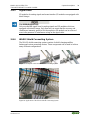
5.6.3 Inserting the I/O Module .................................................................... 64
5.6.4 Removing the I/O Module .................................................................. 65
6 Connect Devices ......................................................................................... 66
6.1 Data Contacts/Internal Bus ..................................................................... 66
6.2 Power Contacts/Field Supply .................................................................. 67
6.3 Connecting a Conductor to the CAGE CLAMP
®
................................... 68
7 Function Description ................................................................................. 69
7.1 Operating System .................................................................................... 69
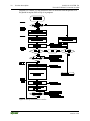
7.1.1 Run-up ................................................................................................ 69
7.1.2 PFC Cycle ........................................................................................... 69
7.2 Process Data Architecture ....................................................................... 71
7.2.1 Basic Structure.................................................................................... 71
7.2.2 Example of an Input Process Image ................................................... 73
7.2.3 Example of an Output Data Process Image ........................................ 74
7.2.4 Process Data MODBUS/TCP ............................................................. 75
7.3 Data Exchange ........................................................................................ 76
7.3.1 Memory Areas .................................................................................... 77
7.3.2 Addressing .......................................................................................... 80
7.3.2.1 Addressing of I/O Modules ........................................................... 81
7.3.2.2 IEC-61131-3 Address Areas .......................................................... 82

WAGO-I/O-SYSTEM 750 Table of Contents 5
750-843 ETHERNET Controller 10 MBit
Manual
Version 1.2.0
7.3.2.3 Absolute Addressing ...................................................................... 82
7.3.3 Data Exchange between MODBUS/TCP Master and I/O Modules ... 84
7.3.4 Data Exchange Between PLC Function (CPU) and I/O Modules ...... 85
7.3.5 Data Exchange between Master and PLC Function (CPU) ................ 86
7.3.5.1 Example of MODBUS/TCP Master and PLC Function (CPU) .... 86
7.3.6 Common access of MODBUS/TCP master and PLC functionality to
outputs ................................................................................................ 87
7.3.7 Application Example .......................................................................... 88
8 Commissioning ........................................................................................... 89
8.1 Connecting Client PC and Fieldbus Nodes ............................................. 90
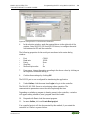
8.2 Allocating the IP Address to the Fieldbus Node ..................................... 91
8.2.1 Assigning IP Address via WAGO-BOOTP-Server ............................ 91
8.2.1.1 Note MAC ID ................................................................................ 92
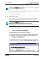
8.2.1.2 Determining IP addresses .............................................................. 93
8.2.1.3 Editing BootP Table ...................................................................... 94
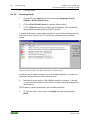
8.2.1.4 Activating BootP ........................................................................... 96
8.2.1.5 Disabling BootP ............................................................................. 97
8.2.1.6 Reasons for Failed IP Address Assignment ................................... 99
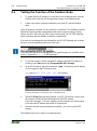
8.3 Testing the Function of the Fieldbus Node ........................................... 100
8.4 Restoring Factory Settings .................................................................... 101
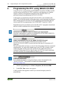
9 Programming the PFC using WAGO-I/O-PRO .................................... 102
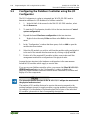
9.1 Configuring the Fieldbus Controller using the I/O Configurator .......... 104
9.2 ETHERNET Libraries for WAGO-I/O-PRO ........................................ 106
9.3 Transfer the IEC program to the controller ........................................... 107
9.3.1 Transfer via Serial Service Port ........................................................ 108
9.3.2 Transfer via ETHERNET ................................................................. 111
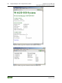
9.4 Reading Out Information about the Fieldbus Controller ...................... 113
10 Diagnostics ................................................................................................ 115
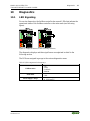
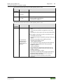
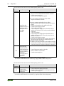
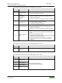
10.1 LED Signaling ....................................................................................... 115
10.1.1 Evaluating Fieldbus Status ............................................................... 116
10.1.2 Evaluating Node Status – I/O LED (Blink Code Table) .................. 117
10.1.2.1 USR LED ..................................................................................... 124
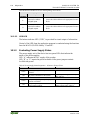
10.1.3 Evaluating Power Supply Status ...................................................... 124
10.2 Fault Behavior ....................................................................................... 125
10.2.1 Loss of Fieldbus ............................................................................... 125
10.2.2 Internal Data Bus Failure.................................................................. 126
11 Fieldbus Communication ........................................................................ 127
11.1 General ETHERNET Information ........................................................ 127
11.1.1 Network Architecture – Principles and Regulations ........................ 129
11.1.1.1 Transmission Media ..................................................................... 130
11.1.1.2 Network Topologies .................................................................... 132
11.1.1.3 Coupler Modules ......................................................................... 134
11.1.1.4 ETHERNET - Transmission Mode ............................................. 135
11.1.1.5 Important Terms .......................................................................... 137
11.1.2 Network Communication ................................................................. 139
11.1.2.1 ETHERNET- Packet .................................................................... 139
11.1.2.2 ETHERNET address (MAC-ID) ................................................. 139
11.1.2.3 Channel access method ................................................................ 140

6 Table of Contents WAGO-I/O-SYSTEM 750
750-843 ETHERNET Controller 10 MBit
Manual
Version 1.2.0
11.1.3 Protocol layer model (Example) ....................................................... 141
11.1.4 Communication Protocols ................................................................ 144
11.1.4.1 TCP (Transmission Control Protocol) ......................................... 144
11.1.4.2 UDP (User Datagram Protocol) ................................................... 144
11.1.5 Configuration and Diagnostics Protocols ......................................... 145
11.1.5.1 BootP (Bootstrap Protocol) .......................................................... 145
11.1.5.2 HTTP (Hypertext Transfer Protocol) ........................................... 146
11.2 MODBUS Functions ............................................................................. 147
11.2.1 General ............................................................................................. 147
11.2.2 Use of the MODBUS Functions ....................................................... 150
11.2.3 Description of the MODBUS Functions .......................................... 151
11.2.3.1 Function Code FC1 (Read Coils) ................................................ 152
11.2.3.2 Function Code FC2 (Read Discrete Inputs) ................................. 154
11.2.3.3 Function Code FC3 (Read Multiple Registers) ........................... 156
11.2.3.4 Function Code FC4 (Read Input Registers) ................................. 157
11.2.3.5 Function Code FC5 (Write Coil) ................................................. 158
11.2.3.6 Function Code FC6 (Write Single Register) ............................... 159
11.2.3.7 Function Code FC7 (Read Exception Status) .............................. 160
11.2.3.8 Function Code FC11 (Get Comm Event Counter) ...................... 161
11.2.3.9 Function Code FC15 (Write Multiple Coils) ............................... 162
11.2.3.10 Function Code FC16 (Write Multiple Registers) ........................ 164
11.2.3.11 Function Code FC23 (Read/Write Multiple Registers) ............... 164
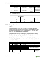
11.2.4 MODBUS Register Mapping ........................................................... 166
11.2.5 MODBUS Registers ......................................................................... 168
11.2.5.1 Accessing Register Values .......................................................... 169
11.2.5.2 Watchdog Registers ..................................................................... 169
11.2.5.3 Diagnostic Registers .................................................................... 174
11.2.5.4 Configuration Registers ............................................................... 175
11.2.5.5 Firmware Information Registers .................................................. 178
11.2.5.6 Constant Registers ....................................................................... 180
12 I/O Modules .............................................................................................. 182
12.1 Overview ............................................................................................... 182
12.2 Process Data Architecture for MODBUS/TCP ..................................... 183
12.2.1 Digital Input Modules....................................................................... 184
12.2.1.1 1 Channel Digital Input Module with Diagnostics ...................... 184
12.2.1.2 2 Channel Digital Input Modules ................................................ 184
12.2.1.3 2 Channel Digital Input Module with Diagnostics ...................... 184
12.2.1.4 2 Channel Digital Input Module with Diagnostics and Output
Process Data ................................................................................. 185
12.2.1.5 4 Channel Digital Input Modules ................................................ 185
12.2.1.6 8 Channel Digital Input Modules ................................................ 185
12.2.1.7 8 Channel Digital Input Module PTC with Diagnostics and Output
Process Data ................................................................................. 186
12.2.1.8 16 Channel Digital Input Modules .............................................. 186
12.2.2 Digital Output Modules .................................................................... 187
12.2.2.1 1 Channel Digital Output Module with Input Process Data ........ 187
12.2.2.2 2 Channel Digital Output Modules .............................................. 187
12.2.2.3 2 Channel Digital Input Modules with Diagnostics and Input
Process Data ................................................................................. 188
12.2.2.4 4 Channel Digital Output Modules .............................................. 189

WAGO-I/O-SYSTEM 750 Table of Contents 7
750-843 ETHERNET Controller 10 MBit
Manual
Version 1.2.0
12.2.2.5 4 Channel Digital Output Modules with Diagnostics and Input
Process Data ................................................................................. 189
12.2.2.6 8 Channel Digital Output Module ............................................... 189
12.2.2.7 8 Channel Digital Output Modules with Diagnostics and Input
Process Data ................................................................................. 190
12.2.2.8 16 Channel Digital Output Modules ............................................ 190
12.2.2.9 8 Channel Digital Input/Output Modules .................................... 191
12.2.3 Analog Input Modules ...................................................................... 192
12.2.3.1 1 Channel Analog Input Modules ................................................ 192
12.2.3.2 2 Channel Analog Input Modules ................................................ 192
12.2.3.3 4 Channel Analog Input Modules ................................................ 193
12.2.3.4 3-Phase Power Measurement Module ......................................... 194
12.2.3.5 8 Channel Analog Input Modules ................................................ 194
12.2.4 Analog Output Modules ................................................................... 195
12.2.4.1 2 Channel Analog Output Modules ............................................. 195
12.2.4.2 4 Channel Analog Output Modules ............................................. 195
12.2.5 Specialty Modules ............................................................................ 196
12.2.5.1 Counter Modules ......................................................................... 197
12.2.5.2 Pulse Width Modules ................................................................... 198
12.2.5.3 Serial Interface Modules with alternative Data Format ............... 199
12.2.5.4 Serial Interface Modules with Standard Data Format ................. 199
12.2.5.5 Data Exchange Module ................................................................ 200
12.2.5.6 SSI Transmitter Interface Modules .............................................. 200
12.2.5.7 Incremental Encoder Interface Modules ...................................... 200
12.2.5.8 DC-Drive Controller .................................................................... 202
12.2.5.9 Stepper Controller ........................................................................ 203
12.2.5.10 RTC Module ................................................................................ 204
12.2.5.11 DALI/DSI Master Module ........................................................... 204
12.2.5.12 DALI Multi-Master Module ........................................................ 205
12.2.5.13 LON
®
FTT Module ...................................................................... 207
12.2.5.14 EnOcean Radio Receiver ............................................................. 207
12.2.5.15 MP Bus Master Module ............................................................... 208
12.2.5.16 Bluetooth
®
RF-Transceiver .......................................................... 208
12.2.5.17 Vibration Velocity/Bearing Condition Monitoring VIB I/O ....... 209
12.2.5.18 KNX/EIB/TP1 Module ................................................................ 210
12.2.5.19 AS-interface Master Module ....................................................... 211
12.2.6 System Modules ............................................................................... 212
12.2.6.1 System Modules with Diagnostics ............................................... 212
12.2.6.2 Binary Space Module .................................................................. 212
13 Use in Hazardous Environments ............................................................ 213
13.1 Marking Configuration Examples ......................................................... 214
13.1.1 Marking for Europe According to ATEX and IEC-Ex .................... 214
13.1.2 Marking for America According to NEC 500 .................................. 219
13.2 Installation Regulations ......................................................................... 220
13.2.1 Special Conditions for Safe Use (ATEX Certificate TÜV 07 ATEX
554086 X) ......................................................................................... 221
13.2.2 Special Conditions for Safe Use (ATEX Certificate TÜV 12 ATEX
106032 X) ......................................................................................... 222
13.2.3 Special Conditions for Safe Use (IEC-Ex Certificate TUN 09.0001 X)223

8 Table of Contents WAGO-I/O-SYSTEM 750
750-843 ETHERNET Controller 10 MBit
Manual
Version 1.2.0
13.2.4 Special Conditions for Safe Use (IEC-Ex Certificate IECEx TUN
12.0039 X) ........................................................................................ 224
13.2.5 Special Conditions for Safe Use according to ANSI/ISA 12.12.01 . 225
List of Figures .................................................................................................... 226
List of Tables ...................................................................................................... 228
=== Ende der Lis te f ür T e xtmar ke V erz eic hnis _vor ne == =

WAGO-I/O-SYSTEM 750 Notes about this Documentation 9
750-843 ETHERNET Controller 10 MBit
Manual
Version 1.2.0
Pos: 7 /A lle Ser ien ( All ge mein e M odul e)/ Über sc hrif ten für all e Ser ie n/Hi nwei se zur D o kume nt ation /Hi nw eise zu dies er D o kume ntati on - Ü ber schr if t 1 @ 4\ mod_1237987661750_21.docx @ 29 029 @ 1 @ 1
1 Notes about this Documentation
Pos: 8 /A lle Ser ien ( All ge mein e M odul e)/ Hin weis e z ur D oku men tati on/H i nweis e/Hi n weis : D okum ent atio n a ufbe wahr e n @ 4 \mod_1237987339812_21.docx @ 29026 @ @ 1
Always retain this documentation!
This documentation is part of the product. Therefore, retain the documentation
during the entire service life of the product. Pass on the documentation to any
subsequent user. In addition, ensure that any supplement to this documentation is
included, if necessary.
Pos: 9 /A lle Ser ien ( All ge mein e M odul e)/ Über sc hrif ten für all e Ser ie n/Hi nwei se zur D o kume nt ation /G ültig kei tsb erei ch - Ü b ersc hrif t 2 @ 1 2\mod_1338912448776_21.docx @ 96469 @ 2 @ 1
1.1 Validity of this Documentation
Pos: 10 /S erie 750 (WAGO-I/O-SYST EM )/Hi n weis e zur D okum ent ati on/G ülti gk eits ber eic h/Gül tig kei ts berei ch Dok umen ta tio n Ko ppler /G ültig k eits ber eich Dok um entati o n Ko ppl er/C ont roll er 7 50- xxxx, ohne Variantenangabe @ 14\mod_1358944039400_21.docx @ 109362 @ @ 1
This documentation is only applicable to the “ETHERNET Controller 10 MBit”
(750-843).
Pos: 11 /S eri e 7 50 ( WA GO-I/ O-SYST EM) /Hi n weis e zur D okum ent ati on/Hi nw eise /Ac htu ng: H in weis zur D oku ment ati on K oppl er- /Acht ung : Hi nw eis z ur D o kume ntati on Kop pler -/C ontr oll er 7 50-xxxx @ 4\ mod_1239095964296_21.docx @ 30118 @ @ 1
The product “ETHERNET Controller 10 MBit” (750-843) shall only be installed
and operated according to the instructions in this manual and the system
description for the WAGO-I/O-SYSTEM 750.
Consider power layout of the WAGO-I/O-SYSTEM 750!
In addition to these operating instructions, you will also need the system
description for the WAGO-I/O-SYSTEM 750, which can be downloaded at
www.wago.com. There, you can obtain important information including
information on electrical isolation, system power and supply specifications.
Pos: 12.1 /All e Seri en ( All ge meine Mo dul e)/H in weis e zur D oku ment ati on/U rh eber sc hutz aus führ lic h @ 4\mod_1235565145234_21.docx @ 27691 @ 2 @ 1
1.2 Copyright
This Manual, including all figures and illustrations, is copyright-protected. Any
further use of this Manual by third parties that violate pertinent copyright
provisions is prohibited. Reproduction, translation, electronic and phototechnical
filing/archiving (e.g., photocopying) as well as any amendments require the
written consent of WAGO Kontakttechnik GmbH & Co. KG, Minden, Germany.
Non-observance will involve the right to assert damage claims.
Pos: 12.2 /Dokumentation allgemein/Gliederungselemente/---Seite nwechs el--- @ 3\ mod_1221108045078_0.docx @ 21810 @ @ 1

10 Notes about this Documentation WAGO-I/O-SYSTEM 750
750-843 ETHERNET Controller 10 MBit
Manual
Version 1.2.0
Pos: 12.3 /All e Seri en ( All ge meine Mo dul e)/Ü bers chr ift en f ür alle S erie n/Hi nwei se z ur Dok um enta tio n/S ymbol e - Ü bers chr ift 2 @ 1 3\mod_1351068042408_21.docx @ 105270 @ 2 @ 1
1.3 Symbols
Pos: 12 .4.1 /Al le Seri en (All gemei ne Mod ule)/ Wichti ge Erl äuter unge n/Sich erheit s- und sonstige Hinweise/Gefahr/Gefa hr: _War nung vor Perso nens chäde n allg emein_ - Erläu terung @ 13\mod_1343309450020_21.docx @ 101029 @ @ 1
Personal Injury!
Indicates a high-risk, imminently hazardous situation which, if not avoided, will
result in death or serious injury.
Pos: 12 .4.2 /Al le Seri en ( All ge mei ne Mo dul e)/ Wic htig e Er lä uter ung en/ Sich erh eits- und sonsti ge Hinw eise/ Gefa hr/Gef ahr: _ Warnu ng vor Per sonen schä den durc h elek trisc hen Stro m_ - Erläuterung @ 13\mod_1343309694914_21.docx @ 101030 @ @ 1
Personal Injury Caused by Electric Current!
Indicates a high-risk, imminently hazardous situation which, if not avoided, will
result in death or serious injury.
Pos: 12 .4.3 /Al le Seri en (All gemei ne Mod ule)/ Wichti ge Erl äuter unge n/Sich erheit s- und so nsti ge H inw eis e/W arn ung/ War nung : _ Warn ung vor P ersone nsch äden allg emei n_ - Erläuterung @ 13\mod_1343309877041_21.docx @ 101035 @ @ 1
Personal Injury!
Indicates a moderate-risk, potentially hazardous situation which, if not avoided,
could result in death or serious injury.
Pos: 12 .4.4 /Al le Seri en (All gemei ne Mod ule)/ Wichti ge Erl äuter unge n/Sich erheit s- und so nsti ge H inw eis e/V orsic ht /Vor sic ht: _War nu ng vor P ers one nsc häde n al lg emei n_ - Erläuterung @ 13\mod_1343310028762_21.docx @ 101038 @ @ 1
Personal Injury!
Indicates a low-risk, potentially hazardous situation which, if not avoided, may
result in minor or moderate injury.
Pos: 12 .4.5 /Al le Seri en (All gemei ne Mod ule)/ Wichti ge Erl äuter unge n/Sich erheit s- und sonstige Hinweise/Achtung/Achtung: _Warnung vor Sachschäden allgemein_ - Erläuterung @ 13\mod_1343310134623_21.docx @ 101041 @ @ 1
Damage to Property!
Indicates a potentially hazardous situation which, if not avoided, may result in
damage to property.
Pos: 12 .4.6 /Al le Seri en (All gemei ne Mod ule)/ Wichti ge Erl äut erung en/ Sich erh eits- und sonstige Hinweise/Achtung/Achtung: _Warnung vor Sachschäden durch elektrostatische Aufladung_ - Erläuterung @ 13\mod_1343310227702_21.docx @ 101044 @ @ 1
Damage to Property Caused by Electrostatic Discharge (ESD)!
Indicates a potentially hazardous situation which, if not avoided, may result in
damage to property.
Pos: 12 .4.7 /Al le Seri en (All gemei ne Mod ule)/ Wichti ge Erl äuter unge n/Sich erheit s- und sonstige Hinweise/Hinweis/Hinweis: _Wichtiger Hinweis allgemein_ - Erläut eru ng @ 13\mod_1343310326906_21.docx @ 101047 @ @ 1
Important Note!
Indicates a potential malfunction which, if not avoided, however, will not result in
damage to property.
Pos: 12.4 .8 /All e Serien ( Allg emeine Modul e)/Wic htig e Erläut erung en/Si cherh eits- und sons tig e Hi nwei se/ Inf or mati on/I nfor ma tio n: _ Wei ter e Inf or matio n al lg emei n_ - Erl äuter ung @ 13\ mod_1343310439814_21.docx @ 101051 @ @ 1

WAGO-I/O-SYSTEM 750 Notes about this Documentation 11
750-843 ETHERNET Controller 10 MBit
Manual
Version 1.2.0
Additional Information:
Refers to additional information which is not an integral part of this
documentation (e.g., the Internet).
Pos: 12.5 /Dokumentation allgemein/Gliederungselemente/---Seite nwechs el--- @ 3\ mod_1221108045078_0.docx @ 21810 @ @ 1

12 Notes about this Documentation WAGO-I/O-SYSTEM 750
750-843 ETHERNET Controller 10 MBit
Manual
Version 1.2.0
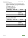
Pos: 12 .6 /All e Seri en (Allg emeine Modul e)/Hi nweis e zur Do kument ation /Zahl ensy steme @ 3\ mod_1221059454015_21.docx @ 21711 @ 2 @ 1
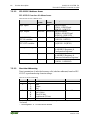
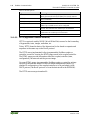
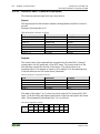
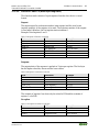
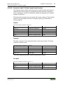
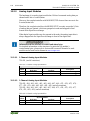
1.4 Number Notation
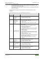
Table 1: Number Notation
Number Code
Example
Note
Decimal
100
Normal notation
Hexadecimal
0x64
C notation
Binary
'100'
'0110.0100'
In quotation marks, nibble separated with
dots (.)
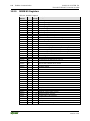
Pos: 12 .7 /All e Seri en (Allg emeine Modul e)/Hi nweis e zur Do kument ation /Schr iftko nventi one n @ 3\mod_1221059521437_21.docx @ 21714 @ 2 @ 1
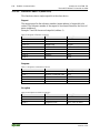
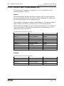
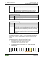
1.5 Font Conventions
Table 2: Font Conventions
Font Type
Indicates
italic
Names of paths and data files are marked in italic-type.
e.g.: C:\Programme\WAGO-I/O-CHECK
Menu
Menu items are marked in bold letters.
e.g.: Save
>
A greater-than sign between two names means the selection of a
menu item from a menu.
e.g.: File > New
Input
Designation of input or optional fields are marked in bold letters,
e.g.: Start of measurement range
“Value”
Input or selective values are marked in inverted commas.
e.g.: Enter the value “4 mA” under Start of measurement range.
[Button]
Pushbuttons in dialog boxes are marked with bold letters in square
brackets.
e.g.: [Input]
[Key]
Keys are marked with bold letters in square brackets.
e.g.: [F5]
Pos: 13 /Doku ment ation all gemei n/Gli eder ungsel eme nte/---Seit en wechs el--- @ 3\mod_1221108045078_0.docx @ 21810 @ @ 1

WAGO-I/O-SYSTEM 750 Important Notes 13
750-843 ETHERNET Controller 10 MBit
Manual
Version 1.2.0
Pos: 14 /Alle Ser ien (Al lge meine Mo dule)/ Über schrif ten für alle Ser ien/ Wichti ge Erlä uteru ngen/ Wichtige Erläuterungen - Übersc hrift 1 @ 4\mod_1241428899156_21.docx @ 32170 @ 1 @ 1
2 Important Notes
Pos: 15.1 /All e Seri en ( All ge meine Do kum ente) ( All ge meine Mo dule) /Wi cht ige Erl äut eru nge n/Ei nl eit ung Wic htige Erl äut eru nge n @ 3 \mod_1221059818031_21.docx @ 21717 @ @ 1
This section includes an overall summary of the most important safety
requirements and notes that are mentioned in each individual section. To protect
your health and prevent damage to devices as well, it is imperative to read and
carefully follow the safety guidelines.
Pos: 15.2 /All e Seri en ( All ge meine Mo dul e)/Ü bers chr ift en f ür alle S erie n/Wi chti ge Erl äuter u ngenR ec htlic he Gr undl ag en - Üb ersc hrift 2 @ 3\ mod_1221060626343_21.docx @ 21726 @ 2 @ 1
2.1 Legal Bases
Pos: 15.3 /All e Seri en ( All ge meine Dokumente) (Allgemeine Module)/Wichtige Erläuterungen/Änderungsvorbehalt - Übers chr ift 3 u nd I nhal t @ 3\mod_1221060036484_21.docx @ 21720 @ 3 @ 1
2.1.1 Subject to Changes
WAGO Kontakttechnik GmbH & Co. KG reserves the right to provide for any
alterations or modifications that serve to increase the efficiency of technical
progress. WAGO Kontakttechnik GmbH & Co. KG owns all rights arising from
the granting of patents or from the legal protection of utility patents. Third-party
products are always mentioned without any reference to patent rights. Thus, the
existence of such rights cannot be excluded.
Pos: 15.4 /Serie 750 (WAGO-I/O-SYST EM)/ Wic htige Erl äuter unge n/Pers onalq uali fikati onPer sonal qual ifika tion 750- xxxx - Ü bersc hrift 3 u nd Inhal t @ 3\mod_1224061208046_21.docx @ 24 063 @ 3 @ 1
2.1.2 Personnel Qualifications
All sequences implemented on WAGO-I/O-SYSTEM 750 devices may only be
carried out by electrical specialists with sufficient knowledge in automation. The
specialists must be familiar with the current norms and guidelines for the devices
and automated environments.
All changes to the coupler or controller should always be carried out by qualified
personnel with sufficient skills in PLC programming.
Pos: 15.5 /Serie 750 (WAGO-I/O-SYST EM)/ Wic htige Erl äuter unge n/Bes timmungsgemäße VerwendungBestimmungsgemäße Verwendung 750-xxxx - Üb erschr if t 3 und I nhal t @ 3 \mod_1224064151234_21.docx @ 24070 @ 3 @ 1
2.1.3 Use of the WAGO-I/O-SYSTEM 750 in Compliance with
Underlying Provisions
Fieldbus couplers, fieldbus controllers and I/O modules found in the modular
WAGO-I/O-SYSTEM 750 receive digital and analog signals from sensors and
transmit them to actuators or higher-level control systems. Using programmable
controllers, the signals can also be (pre-) processed.
The devices have been developed for use in an environment that meets the IP20
protection class criteria. Protection against finger injury and solid impurities up to
12.5 mm diameter is assured; protection against water damage is not ensured.
Unless otherwise specified, operation of the devices in wet and dusty
environments is prohibited.
Operating the WAGO-I/O-SYSTEM 750 devices in home applications without
further measures is only permitted if they meet the emission limits (emissions of
interference) according to EN 61000-6-3. You will find the relevant information
in the section “Device Description” > “Standards and Guidelines” in the manual
for the used fieldbus coupler/controller.

14 Important Notes WAGO-I/O-SYSTEM 750
750-843 ETHERNET Controller 10 MBit
Manual
Version 1.2.0
Appropriate housing (per 94/9/EG) is required when operating the WAGO-I/O-
SYSTEM 750 in hazardous environments. Please note that a prototype test
certificate must be obtained that confirms the correct installation of the system in
a housing or switch cabinet.
Pos: 15.6 /All e Seri en ( All ge meine Do kum ente) ( All ge meine Mo dule) /Wi cht ige Erl äut eru nge n/T echni sc her Zus tan d d er G erä te - Ü bersc hrift 3 un d Inhal t @ 3\mod_1221060446109_21.docx @ 21723 @ 3 @ 1
2.1.4 Technical Condition of Specified Devices
The devices to be supplied ex works are equipped with hardware and software
configurations, which meet the individual application requirements. WAGO
Kontakttechnik GmbH & Co. KG will be exempted from any liability in case of
changes in hardware or software as well as to non-compliant usage of devices.
Please send your request for modified and new hardware or software
configurations directly to WAGO Kontakttechnik GmbH & Co. KG.
Pos: 15.7 /Dokumentation allgemein/Gliederungselemente/---Seite nwechs el--- @ 3\ mod_1221108045078_0.docx @ 21810 @ @ 1

WAGO-I/O-SYSTEM 750 Important Notes 15
750-843 ETHERNET Controller 10 MBit
Manual
Version 1.2.0
Pos: 15 .8 /All e Seri en (Allg emeine Modul e)/Ü berschr ifte n für alle S erie n/Wich tige Er läuter ung enSic herhei tshi nweis e - Übers chrif t 2 @ 6\mod_1260180299987_21.docx @ 46724 @ 2 @ 1
2.2 Safety Advice (Precautions)
Pos: 15.9 /All e Seri en ( All ge meine Do kum ente) ( All ge meine Mo dule) /Wi cht ige Erl äut eru nge n/Si cher hei ts hin weis e/Ei nl eitu ng Sich erh eits hin weis e H ard ware @ 6\mod_1260180170493_21.docx @ 46720 @ @ 1
For installing and operating purposes of the relevant device to your system the
following safety precautions shall be observed:
Pos: 15.1 0. 1 /Al le S eri en ( Allg em ein e Do ku ment e) (Al lg em eine M o dul e)/ Wich tig e Erl äuter u ngen /Sic h erhei ts hinw eise /G efahr /G efahr : N ich t an G erät en unter Sp ann ung arbei te n! @ 6\ mod_1260180365327_21.docx @ 46727 @ @ 1
Do not work on devices while energized!
All power sources to the device shall be switched off prior to performing any
installation, repair or maintenance work.
Pos: 15.1 0. 2 /S erie 750 ( W AGO -I/O-SY ST EM) /Wic htig e Er l äuter ung en /Sic her hei ts- un d s onsti ge H in wei se/G ef ahr/ Gefa hr: Einbau 0750-xxxx nur in Geh äuse n, Schrä nken o der ele ktrisc hen Betr iebsr äume n! @ 6\mod_1260180556692_21.docx @ 46731 @ @ 1
Install the device only in appropriate housings, cabinets or in electrical
operation rooms!
The WAGO-I/O-SYSTEM 750 and its components are an open system. As such,
install the system and its components exclusively in appropriate housings,
cabinets or in electrical operation rooms. Allow access to such equipment and
fixtures to authorized, qualified staff only by means of specific keys or tools.
Pos: 15.1 0. 3 /Al le S eri en ( Allg em ein e Do ku ment e) (Al lg em eine M o dul e)/ Wich tig e Erl äuter u ngen /Sic h erhei ts hinw eise /G efahr /G efahr : U nfal l verh ütung sv orsc hri ft en b each ten! @ 6\mod_1260180657000_21.docx @ 46735 @ @ 1
Pos: 15.1 0. 4 /Al le S eri en ( Allg em ein e Do ku ment e) (Al lg em eine M o dul e)/ Wich tig e Erl äuter u ngen /Sic h erhei ts hinw eise /G efahr /G efahr : A uf normg er echt e n Ansc hlu ss ac hten! @ 6 \mod_1260180753479_21.docx @ 46739 @ @ 1
Pos: 15.1 1. 1 /Al le S eri en ( Allg em ein e Do ku ment e) (Al lg em eine M o dul e)/ Wich tig e Erl äuter ungen /Sic herhei tshin weise /Acht ung/A chtu ng: Defe kte od er besc hädigt e Ger äte austa usch en! @ 6\mod_1260180857358_21.docx @ 46743 @ @ 1
Replace defective or damaged devices!
Replace defective or damaged device/module (e.g., in the event of deformed
contacts), since the long-term functionality of device/module involved can no
longer be ensured.
Pos: 15.1 1. 2 /Al le S eri en ( Allg em ein e Do ku ment e) (Al lg em eine M o dul e)/ Wich tig e Erl äuter u ngen /Sic h erhei ts hinw eise /Ac htu ng/A cht ung : Gerät e vor kri echen den und is olier e nden Sto ffen sch ütz en! @ 6\ mod_1260181036216_21.docx @ 46747 @ @ 1
Protect the components against materials having seeping and insulating
properties!
The components are not resistant to materials having seeping and insulating
properties such as: aerosols, silicones and triglycerides (found in some hand
creams). If you cannot exclude that such materials will appear in the component
environment, then install the components in an enclosure being resistant to the
above-mentioned materials. Clean tools and materials are imperative for handling
devices/modules.
Pos: 15.1 1. 3 /Al le S eri en ( Allg em ein e Do ku ment e) (Al lg em eine M o dul e)/ Wich tig e Erl äuter u ngen /Sic h erhei ts hinw eise /Ac htu ng/A cht ung : Rei nig ung nur mi t zul äss ig en M at erial ien! @ 6\mod_1260181203293_21.docx @ 46751 @ @ 1
Clean only with permitted materials!
Clean soiled contacts using oil-free compressed air or with ethyl alcohol and
leather cloths.
Pos: 15.1 1. 4 /Al le S eri en ( Allg em ein e Do ku ment e) (Al lg em eine M o dul e)/ Wich tig e Erl äuter u ngen /Sic h erhei ts hinw eise /Ac htu ng/A cht ung : K ein K ont a ktspra y verw end en! @ 6\ mod_1260181290808_21.docx @ 46755 @ @ 1

16 Important Notes WAGO-I/O-SYSTEM 750
750-843 ETHERNET Controller 10 MBit
Manual
Version 1.2.0
Do not use any contact spray!
Do not use any contact spray. The spray may impair contact area functionality in
connection with contamination.
Pos: 15.1 1. 5 /Al le S eri en ( Allg em ein e Do ku ment e) (Al lg em eine M o dul e)/ Wich tig e Erl äuter u ngen /Sic h erhei ts hinw eise /Ac htu ng/A cht ung : V erpol ung ver mei de n! @ 6\mod_1260184045744_21.docx @ 46767 @ @ 1
Do not reverse the polarity of connection lines!
Avoid reverse polarity of data and power supply lines, as this may damage the
devices involved.
Pos: 15.1 1. 6 /Al le S eri en ( Allg em ein e Do ku ment e) (Al lg em eine M o dul e)/ Wich tig e Erl äuter u ngen /Sic h erhei ts hinw eise /Ac htu ng/A cht ung : El ektros tatisc he Entl adu ng verm eiden! @ 6\mod_1260181364729_21.docx @ 46759 @ @ 1
Avoid electrostatic discharge!
The devices are equipped with electronic components that may be destroyed by
electrostatic discharge when touched. Please observe the safety precautions
against electrostatic discharge per DIN EN 61340-5-1/-3. When handling the
devices, please ensure that environmental factors (personnel, work space and
packaging) are properly grounded.
Pos: 16 /D o kume nt ation all ge mein/ Glie der ungs ele mente /---Seit en wechs el--- @ 3\mod_1221108045078_0.docx @ 21810 @ @ 1

WAGO-I/O-SYSTEM 750 Important Notes 17
750-843 ETHERNET Controller 10 MBit
Manual
Version 1.2.0
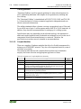
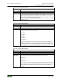
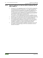
Pos: 17 /A ll e Ser ien (Al lg emei ne M od ule)/ Wic hti ge Erlä uter ung en/ Spez i elle Ein satz besti m mung en für ETH ERN ET- Gerät e @ 12\mod_1336642945500_21.docx @ 94792 @ 2 @ 1
2.3 Special Use Conditions for ETHERNET Devices
If not otherwise specified, ETHERNET devices are intended for use on local
networks. Please note the following when using ETHERNET devices in your
system:
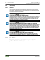
• Do not connect control components and control networks to an open
network such as the Internet or an office network. WAGO recommends
putting control components and control networks behind a firewall.
• Limit physical and electronic access to all automation components to
authorized personnel only.
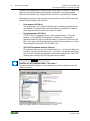
• Change the default passwords before first use! This will reduce the risk of
unauthorized access to your system.
• Regularly change the passwords used! This will reduce the risk of
unauthorized access to your system.
• If remote access to control components and control networks is required,
use a Virtual Private Network (VPN).
• Regularly perform threat analyses. You can check whether the measures
taken meet your security requirements.
• Use “defense-in-depth” mechanisms in your system's security configuration
to restrict the access to and control of individual products and networks.
Pos: 18 /Doku ment ation all gemei n/Gli eder ungsel eme nte/---Seit en wechs el--- @ 3\mod_1221108045078_0.docx @ 21810 @ @ 1

18 System Description WAGO-I/O-SYSTEM 750
750-843 ETHERNET Controller 10 MBit
Manual
Version 1.2.0
Pos: 19.1 /All e Seri en ( All ge meine Mo dul e)/Ü bers chr ift en f ür alle S erie n/Sys te mbesc hrei bung Sy stem besc hrei bu ng - Ü bersc hrift 1 @ 3\ mod_1231491805015_21.docx @ 25850 @ 1 @ 1
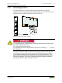
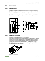
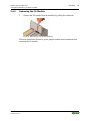
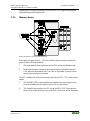
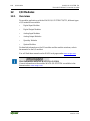
3 System Description
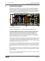
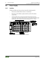
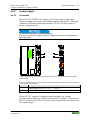
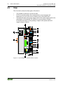
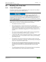
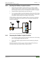
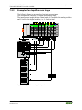
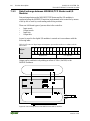
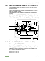
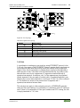
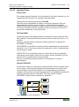
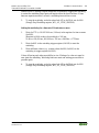
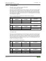
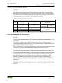
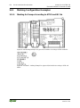
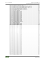
Pos: 19.2 /Serie 750 (WAGO-I/O-SYST EM )/ Syst emb eschr ei bung /Ger ät und S yste m/S yste mb esc hrei bung - Auf bau Fel db usk not en @ 3\mod_1231492904937_21.docx @ 25867 @ @ 1
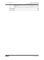
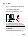
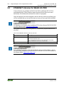
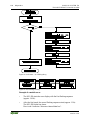
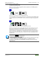
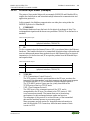
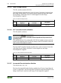
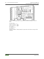
The WAGO-I/O-SYSTEM 750 is a modular, fieldbus-independent input/output
system (I/O system). The configuration described here consists of a fieldbus
coupler/controller (1) and the modular I/O modules (2) for any signal shapes that
form the fieldbus node together. The end module (3) completes the node and is
required for correct operation of the fieldbus node.
Figure 1: Fieldbus Node (Example)
Fieldbus couplers/controllers are available for different fieldbus systems.
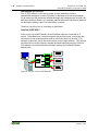
Pos: 19.3 /Serie 750 (WAGO-I/O-SYST EM )/ Syst emb eschr ei bung /Ger ät und S yste m/S yste mb esc hrei bung - Bes chr ei bung Au fba u Fel dbu s knote n (S tand ard) @ 3\mod_1231493221890_21.docx @ 25870 @ @ 1
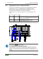
The standard fieldbus couplers/controllers and extended ECO fieldbus couplers
contain the fieldbus interface, electronics and a power supply terminal. The
fieldbus interface forms the physical interface to the relevant fieldbus. The
electronics process the data of the I/O modules and make it available for the
fieldbus communication. The 24 V system supply and the 24 V field supply are
fed in via the integrated power supply terminal.
The fieldbus coupler/controller exchanges process data with the respective control
via the respective fieldbus. The programmable fieldbus controllers (PFC) allow
implementation of additional PLC functions. WAGO-I/O-PRO is used to program
the fieldbus controllers according to IEC 61131-3.
Pos: 19.4 /Serie 750 (WAGO-I/O-SYST EM)/ Syst embes chr ei bung /Ger ät und Sys te m/S yste mb eschr ei bung - Ko mmuni kati on Klem menbus , LEDs , 3-Leiter tec h ni k @ 3\ mod_1231493520906_21.docx @ 25877 @ @ 1
I/O modules for diverse digital and analog I/O signals as well as special functions
can be connected to the fieldbus coupler/controller. The communication between
the fieldbus coupler/controller and the I/O modules is carried out via an internal
bus.
The components of the WAGO-I/O-SYSTEM 750 have clear termination points,
light emitting diodes for status display, plug-in mini WSB tags and group marker
cards for labeling.
The 1, 2 or 3 wire technology supplemented by a ground wire connection allows
for direct sensor or actuator wiring.
Pos: 19.5 /Dokumentation allgemein/Gliederungselemente/---Seite nwechs el--- @ 3\ mod_1221108045078_0.docx @ 21810 @ @ 1

WAGO-I/O-SYSTEM 750 System Description 19
750-843 ETHERNET Controller 10 MBit
Manual
Version 1.2.0
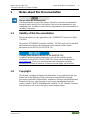
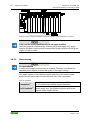
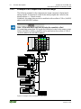
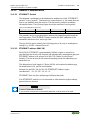
Pos: 19.6 /Serie 750 (WAGO-I/O-SYST EM )/ Syst emb eschr ei bung /Ger ät und S yste m/Fer tig ung snu mm er @ 3\ mod_1225444612218_21.docx @ 24889 @ 2 @ 1
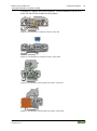
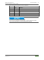
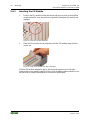
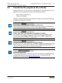
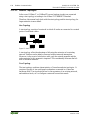
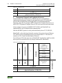
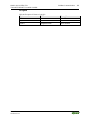
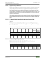
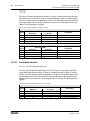
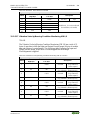
3.1 Manufacturing Number
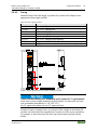
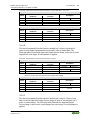
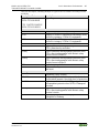
The serial number indicates the delivery status directly after production. This
number is part of the labeling on the side of each component.
In addition, the serial number is printed on the cover cap of the configuration and
programming interface of the fieldbus coupler/controller, so that it can also be
read when installed.
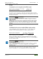
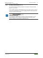
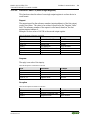
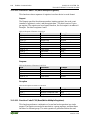
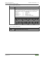
Figure 2: Labeling on the Side of a Component (Example)
Manufacturing number
01
03
01
02
03
-
B060606
Calendar
week
Year
Software
version
Hardware
version
Firmware
loader
version
Internal
number
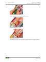
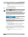
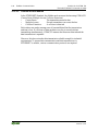
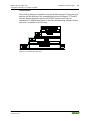
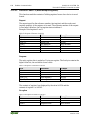
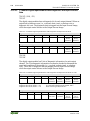
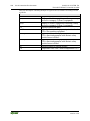
Figure 3: Example of a Manufacturing Number
The manufacturing number consists of the production week and year, the software
version (if available), the hardware version of the component, the firmware loader
(if available) and further internal information for WAGO Kontakttechnik GmbH
& Co. KG.
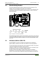
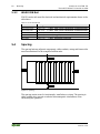
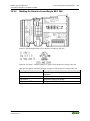
Pos: 19.7 /Serie 750 (WAGO-I/O-SYST EM )/ Syst emb eschr ei bung /Ger ät und S yste m/Har d war e-Adr ess e (M AC-ID ) @ 7 \mod_1270708464299_21.docx @ 54960 @ 2 @ 1
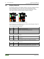
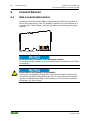
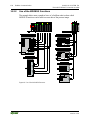
3.2 Hardware Address (MAC ID)
Each ETHERNET Controller 10 MBit has an internationally unambiguous
physical address, referred to as the MAC-ID (Media Access Control Identity).
As part of the labeling on the right side of this component, the MAC ID is printed
in the block diagram of the fieldbus coupler/controller.
In addition, the MAC ID is located on the paper strip with two self-adhesive peel-
off strips on the left side of the fieldbus coupler/controller.
The MAC ID has a fixed length of 6 bytes (48 bits) which are presented
hexadecimal. The first three bytes identify the manufacturer (e.g. 00:30 DE for
WAGO). The second 3 bytes comprise the unique serial number of the hardware.
Pos: 19.8 /Dokumentation allgemein/Gliederungselemente/---Seite nwechs el--- @ 3\ mod_1221108045078_0.docx @ 21810 @ @ 1

20 System Description WAGO-I/O-SYSTEM 750
750-843 ETHERNET Controller 10 MBit
Manual
Version 1.2.0
Pos: 19.9 /Serie 750 (WAGO-I/O-SYSTEM)/Systembeschreibung/Gerät und System/Komponenten-Update-Mat ri x @ 3 \ mod_1231757422359_21.docx @ 25928 @ 2 @ 1
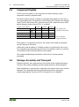
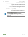
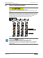
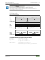
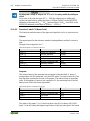
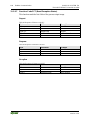
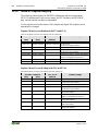
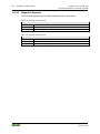
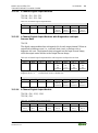
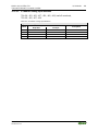
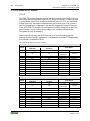
3.3 Component Update
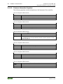
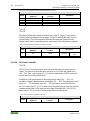
For the case of an update of one component, the lateral marking on each
component contains a prepared matrix.
This matrix makes columns available for altogether three updates to the entry of
the current update data, like production order number (NO; starting from calendar
week 13/2004), date stamp (DS), software version (SW), hardware version (HW)
and the firmware loader version (FWL, if available).
Current version data for
1. Update
2. Update
3. Update
Production order no.
NO
only starting from
Date stamp
DS
calendar week 13/2004
Software version
SW
Hardware version
HW
Firmware loader vers.
FWL
only for fieldbus
couplers/controllers
If the update of a component took place, the current version data are registered
into the columns of the matrix.
Additionally with the update of a fieldbus coupler or controller also the cover of
the configuration and programming interface of the fieldbus coupler or controller
is imprinted with the current production order number.
The original manufacturing information on the device's housing remains
unchanged.
Pos: 19.1 0 / Ser ie 7 50 ( WAG O-I/ O-SYST EM)/ Syste mbesc hrei bung/G erät und Syst em/L ageru ng, Kom missi onieru ng und Tr ansp ort @ 3\mod_1225446600609_21.docx @ 24897 @ 2 @ 1
3.4 Storage, Assembly and Transport
Whenever possible, the components are to be stored in their original packaging.
Likewise, the original packaging provides optimal protection during transport.
When assembling or repacking the components, the contacts must not be soiled or
damaged. The components must be stored and transported in appropriate
containers/packaging. Thereby, the ESD information is to be regarded.
Pos: 19.1 1 /D ok um entati o n allg em ein/ Gli eder ung sel eme nte/---S eit enw echs el--- @ 3\ mod_1221108045078_0.docx @ 21810 @ @ 1
Page is loading ...
Page is loading ...
Page is loading ...
Page is loading ...
Page is loading ...
Page is loading ...
Page is loading ...
Page is loading ...
Page is loading ...
Page is loading ...
Page is loading ...
Page is loading ...
Page is loading ...
Page is loading ...
Page is loading ...
Page is loading ...
Page is loading ...
Page is loading ...
Page is loading ...
Page is loading ...
Page is loading ...
Page is loading ...
Page is loading ...
Page is loading ...
Page is loading ...
Page is loading ...
Page is loading ...
Page is loading ...
Page is loading ...
Page is loading ...
Page is loading ...
Page is loading ...
Page is loading ...
Page is loading ...
Page is loading ...
Page is loading ...
Page is loading ...
Page is loading ...
Page is loading ...
Page is loading ...
Page is loading ...
Page is loading ...
Page is loading ...
Page is loading ...
Page is loading ...
Page is loading ...
Page is loading ...
Page is loading ...
Page is loading ...
Page is loading ...
Page is loading ...
Page is loading ...
Page is loading ...
Page is loading ...
Page is loading ...
Page is loading ...
Page is loading ...
Page is loading ...
Page is loading ...
Page is loading ...
Page is loading ...
Page is loading ...
Page is loading ...
Page is loading ...
Page is loading ...
Page is loading ...
Page is loading ...
Page is loading ...
Page is loading ...
Page is loading ...
Page is loading ...
Page is loading ...
Page is loading ...
Page is loading ...
Page is loading ...
Page is loading ...
Page is loading ...
Page is loading ...
Page is loading ...
Page is loading ...
Page is loading ...
Page is loading ...
Page is loading ...
Page is loading ...
Page is loading ...
Page is loading ...
Page is loading ...
Page is loading ...
Page is loading ...
Page is loading ...
Page is loading ...
Page is loading ...
Page is loading ...
Page is loading ...
Page is loading ...
Page is loading ...
Page is loading ...
Page is loading ...
Page is loading ...
Page is loading ...
Page is loading ...
Page is loading ...
Page is loading ...
Page is loading ...
Page is loading ...
Page is loading ...
Page is loading ...
Page is loading ...
Page is loading ...
Page is loading ...
Page is loading ...
Page is loading ...
Page is loading ...
Page is loading ...
Page is loading ...
Page is loading ...
Page is loading ...
Page is loading ...
Page is loading ...
Page is loading ...
Page is loading ...
Page is loading ...
Page is loading ...
Page is loading ...
Page is loading ...
Page is loading ...
Page is loading ...
Page is loading ...
Page is loading ...
Page is loading ...
Page is loading ...
Page is loading ...
Page is loading ...
Page is loading ...
Page is loading ...
Page is loading ...
Page is loading ...
Page is loading ...
Page is loading ...
Page is loading ...
Page is loading ...
Page is loading ...
Page is loading ...
Page is loading ...
Page is loading ...
Page is loading ...
Page is loading ...
Page is loading ...
Page is loading ...
Page is loading ...
Page is loading ...
Page is loading ...
Page is loading ...
Page is loading ...
Page is loading ...
Page is loading ...
Page is loading ...
Page is loading ...
Page is loading ...
Page is loading ...
Page is loading ...
Page is loading ...
Page is loading ...
Page is loading ...
Page is loading ...
Page is loading ...
Page is loading ...
Page is loading ...
Page is loading ...
Page is loading ...
Page is loading ...
Page is loading ...
Page is loading ...
Page is loading ...
Page is loading ...
Page is loading ...
Page is loading ...
Page is loading ...
Page is loading ...
Page is loading ...
Page is loading ...
Page is loading ...
Page is loading ...
Page is loading ...
Page is loading ...
Page is loading ...
Page is loading ...
Page is loading ...
Page is loading ...
Page is loading ...
Page is loading ...
Page is loading ...
Page is loading ...
Page is loading ...
Page is loading ...
Page is loading ...
Page is loading ...
Page is loading ...
Page is loading ...
Page is loading ...
Page is loading ...
Page is loading ...
Page is loading ...
Page is loading ...
Page is loading ...
Page is loading ...
Page is loading ...
Page is loading ...
Page is loading ...
Page is loading ...
Page is loading ...
Page is loading ...
Page is loading ...
Page is loading ...
-
 1
1
-
 2
2
-
 3
3
-
 4
4
-
 5
5
-
 6
6
-
 7
7
-
 8
8
-
 9
9
-
 10
10
-
 11
11
-
 12
12
-
 13
13
-
 14
14
-
 15
15
-
 16
16
-
 17
17
-
 18
18
-
 19
19
-
 20
20
-
 21
21
-
 22
22
-
 23
23
-
 24
24
-
 25
25
-
 26
26
-
 27
27
-
 28
28
-
 29
29
-
 30
30
-
 31
31
-
 32
32
-
 33
33
-
 34
34
-
 35
35
-
 36
36
-
 37
37
-
 38
38
-
 39
39
-
 40
40
-
 41
41
-
 42
42
-
 43
43
-
 44
44
-
 45
45
-
 46
46
-
 47
47
-
 48
48
-
 49
49
-
 50
50
-
 51
51
-
 52
52
-
 53
53
-
 54
54
-
 55
55
-
 56
56
-
 57
57
-
 58
58
-
 59
59
-
 60
60
-
 61
61
-
 62
62
-
 63
63
-
 64
64
-
 65
65
-
 66
66
-
 67
67
-
 68
68
-
 69
69
-
 70
70
-
 71
71
-
 72
72
-
 73
73
-
 74
74
-
 75
75
-
 76
76
-
 77
77
-
 78
78
-
 79
79
-
 80
80
-
 81
81
-
 82
82
-
 83
83
-
 84
84
-
 85
85
-
 86
86
-
 87
87
-
 88
88
-
 89
89
-
 90
90
-
 91
91
-
 92
92
-
 93
93
-
 94
94
-
 95
95
-
 96
96
-
 97
97
-
 98
98
-
 99
99
-
 100
100
-
 101
101
-
 102
102
-
 103
103
-
 104
104
-
 105
105
-
 106
106
-
 107
107
-
 108
108
-
 109
109
-
 110
110
-
 111
111
-
 112
112
-
 113
113
-
 114
114
-
 115
115
-
 116
116
-
 117
117
-
 118
118
-
 119
119
-
 120
120
-
 121
121
-
 122
122
-
 123
123
-
 124
124
-
 125
125
-
 126
126
-
 127
127
-
 128
128
-
 129
129
-
 130
130
-
 131
131
-
 132
132
-
 133
133
-
 134
134
-
 135
135
-
 136
136
-
 137
137
-
 138
138
-
 139
139
-
 140
140
-
 141
141
-
 142
142
-
 143
143
-
 144
144
-
 145
145
-
 146
146
-
 147
147
-
 148
148
-
 149
149
-
 150
150
-
 151
151
-
 152
152
-
 153
153
-
 154
154
-
 155
155
-
 156
156
-
 157
157
-
 158
158
-
 159
159
-
 160
160
-
 161
161
-
 162
162
-
 163
163
-
 164
164
-
 165
165
-
 166
166
-
 167
167
-
 168
168
-
 169
169
-
 170
170
-
 171
171
-
 172
172
-
 173
173
-
 174
174
-
 175
175
-
 176
176
-
 177
177
-
 178
178
-
 179
179
-
 180
180
-
 181
181
-
 182
182
-
 183
183
-
 184
184
-
 185
185
-
 186
186
-
 187
187
-
 188
188
-
 189
189
-
 190
190
-
 191
191
-
 192
192
-
 193
193
-
 194
194
-
 195
195
-
 196
196
-
 197
197
-
 198
198
-
 199
199
-
 200
200
-
 201
201
-
 202
202
-
 203
203
-
 204
204
-
 205
205
-
 206
206
-
 207
207
-
 208
208
-
 209
209
-
 210
210
-
 211
211
-
 212
212
-
 213
213
-
 214
214
-
 215
215
-
 216
216
-
 217
217
-
 218
218
-
 219
219
-
 220
220
-
 221
221
-
 222
222
-
 223
223
-
 224
224
-
 225
225
-
 226
226
-
 227
227
-
 228
228
-
 229
229
-
 230
230
-
 231
231
-
 232
232
-
 233
233
-
 234
234


WAGO ETHERNET TCP/IP Programmable Fieldbus Controller User manual
- Type
- User manual
- This manual is also suitable for
Ask a question and I''ll find the answer in the document
Finding information in a document is now easier with AI
Related papers
Other documents
-
Hager TX216 Product Documentation
-
 Enertronica Santerno SINUS H ZZ0176102 User manual
-
ABB DG/S 1.1 User manual
-
Rosemount FG-110 User manual
-
 myTEM SmartHome MTBAS-100-WL Installation guide
-
Phoenix Contact GW PL ETH BUS Series User manual
-
 Above All ABWP20LED40DS User manual
-
-
 West Control Solutions Rail line MODTCP User manual
-
Aceinna eB2110 User manual


